Close
0%
0%

SPDT16: 16-bits arithmetic unit with relays

Let's imagine I could get about 200 SPDT relays. Of course I would know what to do with them :-D But will 200 be enough ?

Similar projects worth following
This circuit is meant to be a demonstration/attraction that illustrates where/how computers started, a century ago. I wanted to build one for the kids, to stimulate their curiosity and play safely with digital ideas.

It's not a real computer but a toy calculator that takes two 16-bits operands (in binary/hex, let's be educational!) and performs add/subtract/multiply/divide "the old way" (like when ENIAC was still a thing).
If it is ever completed, it should be obvious why we don't use this technology anymore but I hope that fun will have been had, binary will have been learned and relays will have happily clicked!

One lesson I learned: if I ever have to do it again, I'll use DPDT and higher voltages.

Oh wait...

2016-10: This projet is now shelved. But you must have a look at #AMBAP: A Modest Bitslice Architecture Proposal, #YGREC16 - YG's 16bits Relay Electric Computer and #YGREC-РЭС15-bis because they are an extension of this project. How fun is that ?


After I started #Discrete YASEP then moved to lower tech in #Yet Another (Discrete) Clock, I continued my spiraling descent into history with #Clockwork germanium and with this project, I hope I've touched the bottom... (I've skipped the thermionic vacuum tubes for excellent reasons).

New ! More relay madness at #Relay-based projects

Unlike #RISC Relay CPU, I just want to show kids how computations can be performed mechanically. So let's make the craziest, most horrible contraption possible :-D "You see, kids, be happy we have transistors today. Can you imagine that electromechanical thing computing a Youtube video clip ???"

Why 16 bits ? 4 bits looks underwhelming (yet cool) It could be 8, could be 10 or 12 but 16 bits start to be meaningful, 0 to 65535, and that's the minimum used by real computers. And the design is not really dependent on the number of bits so hopefully, I would make a 20 bits version ("See, it can count to more than one million but it would kill the contacts !"). Besides, I have TIL311s (no #DYPLED yet but it will come) and hex rotary buttons so it makes a nice introduction to binary/hex codes.


The machine is made of 3 types of boards that are chained together:
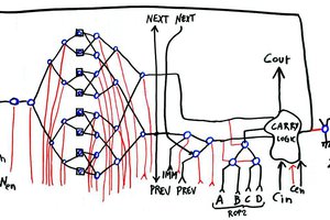
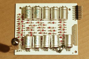
  • A boards: Input+Arithmetic+shift+register units that store and compute one nibble (4 bits wide, (see Bislice for 2 bits)
  • B boards: A smaller version with just 4-bits shift+registers, used for MUL/DIV
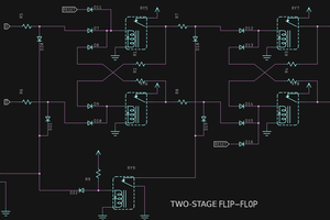
  • C board: the control board that generates all the necessary signals (see Sequencer design for the pulse generator)

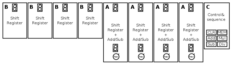
Each board can be built separately, the only constraint is that there must be as many A and B boards. The design is scalable, it can work with 4, 8, 12, 16 bits data or more (the sequencer must be adapted for each case).


How to perform additions:

  1. Turn power on and press the CLEAR button (this will clear the accumulator, even though it should be clear on power-on)
  2. Turn the hexadecimal input knobs to select one number.
  3. Select the "ADD" mode and press the "MEM" button : the input value is transferred in the accumulator.
  4. Select a different input value, then press MEM again : the sum gets registered in the accumulator and displayed in hexadecimal.
  5. Repeat step 4) for all the numbers you want to add together
  6. For subtraction, switch to the SUB mode and continue as with 4)

I use a lot of electronic tricks found in http://relaysbc.sourceforge.net
https://web.cecs.pdx.edu/~harry/Relay/RelayPaper.htm is an excellent reference as well !
More references at Rationale and general idea


Logs:
1. Power supply
2. Freewheel diodes
3. SPDT×72
4. Glühbirnchen
5. Rationale and general idea
6. Power supplies (2)
7. Die Glühbirnchen sind da !
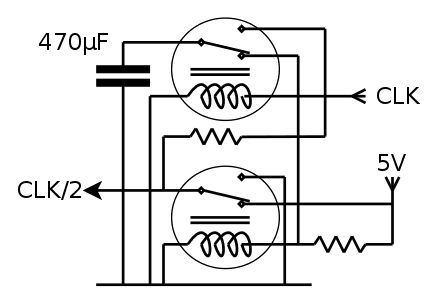
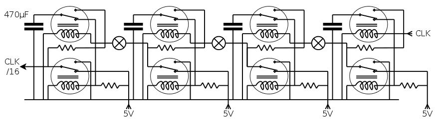
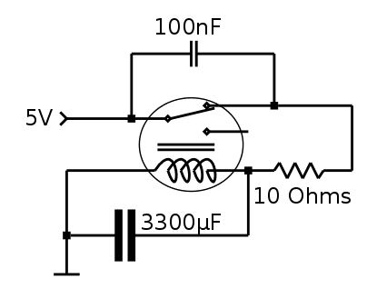
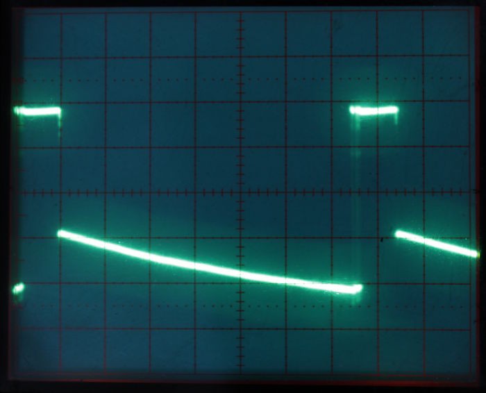
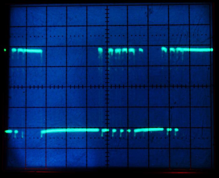
8. How can I make a low-frequency oscillator with a relay (or more ?)
9. The relays are here too !
10. A sick trick for the multiplies
11. The hexadecimal rotary switches
12. A slice of ALU
13. Signed or unsigned ?
14. Multiplication and Division
15. Save the relays !
16. Faster ripple
17. One bitslice
18. New slice
19. Bislice
20. 2 relays, 1 lamp
21. Bad vibes
22. Simple oscillator
23. Lamp-relay oscillator ?
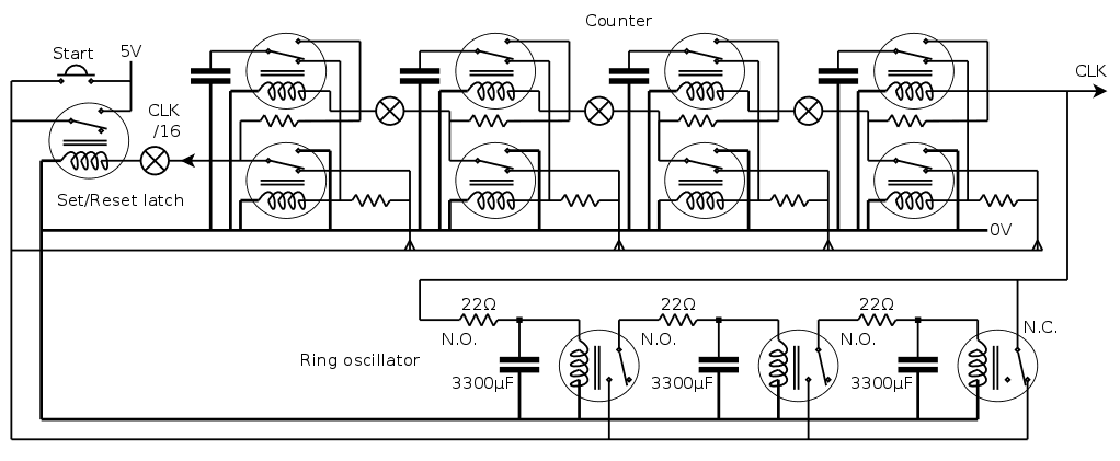
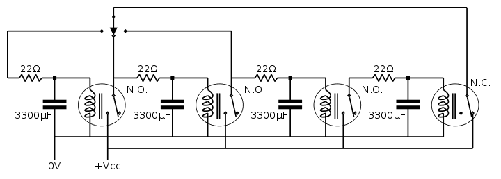
24. Relay ring oscillator
25. Sequencer design
26. Start/Stop and other bugs
27. Where to find the parts ?
28. Change of strategy

DELTA_DC-DC_DNL10S0A0R16PFD.pdf

Datasheet of Delphi DNL, Non-Isolated Point of Load - DC/DC Power Modules: 8.3-14Vin, 0.75-5.0V/16A out

Adobe Portable Document Format - 755.93 kB - 04/18/2016 at 02:49

Preview
Download

  • 300 × РЭС15 (3V version) Russian mini-relay
  • 5 × DNL10S0A0R16PFD DELTA DC/DC SIP module
  • 300 × 3mm Glühbirnchen 3V tiny incandescent lamp
  • 5 × Hexadecimal rotary switch
  • 10 × TIL311 Hexadeciimal LED display (obsolete, use #PICTIL instead)

  • Change of strategy

    Yann Guidon / YGDES09/08/2016 at 03:22 0 comments

    It appears that I have more relays than I planned. Like, twice more. This makes me think about how to better use them...

    More relays means the possibility of a more complex system, which remains to be determined. However the current design still must be completed because the critical electrical design elements are studied. I will probably make a smaller design, with 8 or 10 bits maybe... More relays for the larger design !

    Any suggestion for the use of more relays ? I have a vague idea but it might still be too ambitious...

    Meanwhile, I'll play with some of these relays with the kids, during the workshops :-)


    20160910: The answers are now there : #AMBAP: A Modest Bitslice Architecture Proposal

  • Where to find the parts ?

    Yann Guidon / YGDES05/12/2016 at 02:13 0 comments

    Since the project has been featured on this website, I have received questions, mostly concerning my sources for the parts.

    The relays come from http://www.ebay.com/usr/alex550_2 in Ukraine. He's a very nice seller, who sometimes stuffed some empty space in the boxes with a few extras. He also sold me the 18KHz quartz resonators that are used in #Yet Another (Discrete) Clock. You can find him here too ! @qro_team

    The miniature lamps come from eBay user minifux in Germany. Watch his items on the german site as many don't seem to appear anywhere else than http://www.ebay.de/sch/minifux1/m.html (He also has TONS of germanium parts that I use in #Clockwork germanium)

    The DC/DC modules come from http://www.ebay.com/usr/exdwh

    Yeah, eBay is pretty awesome :-)

    Thank you guys !

  • Start/Stop and other bugs

    Yann Guidon / YGDES05/09/2016 at 20:34 0 comments

    It didn't take long to find problems in the last diagram of Sequencer design

    One is a stupid bug : the ring oscillator's output feeds itself and other relays. When the output relay is close, it feeds +Vcc to the capacitor and the other relays. But when it is open, the capacitor has more coils to drive and it empties faster...

    A simple diode should solve this.

    Now, this diode drops some voltage. I have tested the ring oscillator down to about 3.4V so 4.3V should be OK.

    The clock output also feeds the pulse counter and the main CLK output. This last signal must be buffered through another relay, with the coil in series with the first counter's relay. I've added a lamp in series but I'm not sure it will actually change anything, or shine visibly. We'll see.

    Fun fact : no freewheel diode is necessary because the overshoot will charge the ring oscillator's first capacitor. The changes are outlined in red.

    The final counter stage is a more intricate problem, though.

  • Sequencer design

    Yann Guidon / YGDES05/08/2016 at 16:59 5 comments

    It's time to think more about the sequencial logic.

    For a 16×16 bits mulitplication (or division), 32 clock pulses are necessary. In general 2N pulses are required to calculate the product of N-bits operands. What is the most efficient design that creates just the needed number of pulses ?

    Shift registers

    A cascade of DFF is easy to conceptualize. The operation mode is simple:

    • Clear all the DFF
    • Apply the clock pulses to all the DFF, their data input coming from the precedent DFF's data output. Except for the very first input which is tied to logic 1.
    • When the pulses are sent, the shift register will be progressively filled with 1s
    • The last DFF will indicate that the counter has expired when the 1 reaches the end of the cascade.

    Cost: 2×2N relays, or 64 SPDT in our case...

    Johnson counter

    This is a great enhancement to the previous system. The propagation of the 1s is recirculated after undergoing a logical inversion, which cuts the number of relays in half.

    With 32 relays, 32 pulses can be generated before the state of the shift register is repeated. However the end of the cascade will see a change from 0 to 1 then back to 0. This last front must be detected with a "divide by two" circuit, adding 2 relays... so the total is 34 SPDT. Nicer but still not there...

    Synchronous binary counter

    In the spirit of Simon Winder's design, we can also use binary coding to create the counter. The number of gates/relays is reduced to O(log2(N)) but multiplying factors appear because there are 2×log2(N) DFF but also more gates to compute the next state, using an incrementer circuit. This circuit is described in the above video/link and in the below illustration coming from the ever useful Relay Trainer project page:

    At 2 SPDT per bit, a 16-bits counter requires 4 stages × 4 SPDT => 16×SPDT.

    That's better but... still not optimal.


    This can be further reduced by using an asynchronous ripple counter, which is a cascade of "divide by two" circuits. It's one very simple circuit that is based on the D-flip-flop:

    Now two things must be done:

    1. loop the data output back to the data input
    2. invert the value (exchange the 0V and 5V contacts) for the output relay.

    This way, for each clock pulse, the relay will flip its state. This divides the clock frequency by two !

    For 16 bits, the circuit must count from 0 to 15, so there are 2×4 SPDT relays in a cascade.

    This is 8×SPDT. A last circuit is necessary to make this divider fully functional: a set-reset latch must control the start and stop conditions.

    With 4 relays for the clock generation, and 10 relays for the counter, the total is 14 SPDT. The following version uses only 12:

    When you press the Start button, it should generate 16 short pulses on the CLK output.


    Erratum : the above circuit would only generate 8 pulses... I must redesign the set/reset latch. The last DFF stage is almost transparent/useless...


    Update n°2: the above circuit needs a diode to isolate the capacitor discharge from the other coils, or the time constant will be reduced...

  • Relay ring oscillator

    Yann Guidon / YGDES05/08/2016 at 05:24 0 comments

    I think I finally nailed it :-)

    I have had difficulties with the concept of a relay ring oscillator because relays don't behave like transistors. With this kind of inverting gates, you just use odd numbers of gates with capacitors and that's it.

    For relays it must be different. The trick is to use only one inverting gate (at the right) which is normally closed (N.C.). The others are non-inverting gates (N.O.) which add more delay.

    It's going to be pretty clickety and remove concerns about bounces on the contacts. It can also control frequency and duty cycles easily, by adding more delay gates, making a more efficient overall design. For example it can generate a clock signal with 1/4 duty cycle, so the series lamp gets turned on during less time, consuming less and allowing faster operation.


    Update (20160509): it works !

    It is difficult to record the sound, I hope you can hear it.

    With 3×(3300µF/22Ω), the clock period is around 600ms, or 1.6Hz, which is reasonable (not too fast, not too slow).

  • Bad relay choice ?

    Yann Guidon / YGDES05/08/2016 at 03:10 3 comments

    I noticed only now some details I didn't see before: these 3V relays are rated for 150V 100mA max. (under which conditions ?)

    Given that it takes 60mA to energise one coil, the amplification coefficient is barely 2 and the design expects more.

    It was a good idea to connect coils in series wherever possible. Control signals still require a large fanout and I'll probably have to implement a 2-levels signal tree (with repeaters for each nibble or two).

    Given the current handling, it would have been wiser to opt for a higher coil voltage, which reduces the required current, thus a better amplification factor.

    That, and DPDT, will be considerations for a next version, if any !

  • Lamp-relay oscillator ?

    Yann Guidon / YGDES05/06/2016 at 08:28 0 comments

    I replaced the resistor with one of the lamps and the result is pretty interesting, even though less reliable than with 10 Ohms.

    The frequency is lower, like 3Hz instead of 13Hz. The lamp slows the charge down as it warms up, but the resistance increases with the temperature. It's a fragile balance and often the system gets stuck in micro-oscillations, due to bouncing.

    Using the thermal delay is attractive because it is both "visually explicit" and takes less room. I'll be thinking about it while sleeping ;-)

  • Simple oscillator

    Yann Guidon / YGDES05/06/2016 at 06:30 0 comments

    After some trials and errors, I've settled to this system:

    3300µF was what I had easy access to, I wanted to make a ring oscillator so I looked for 3 identical high-valued electrolytic capacitors and they looked nice.

    I get about 12Hz. The frequency is affected by the series resistor, which I had to reduce in order to keep a stable oscillation because it doesn't start up quiclky.

    I initially started with a safe value of 47 Ohms because the coil is 35 Ohms but it didn't work well. It was a bit better at 22 but 10 Ohms keeps oscillating at 4V. The inrush current is in the order of 400mA... (coil dropped below 1V, Vcc=5V, I=(5-1)/10=0.4A)

    Maybe I should add a lamp in series to keep it running ?

    Anyway, with 10 Ohms, the charging pulse lasts about 10ms, with 65ms of discharge.

    That's about 1/75ms=13Hz.

    Zooming in the charging pulse, I can see strong ringing...

    No wonder my frequency meter was confused !

    More action on youtube:


    20161107: Oh yeah, the inrush current is 4× the rated 100mA current... No wonder it doesn't work well.

    I'm about to make a longer ring oscillator usign PBRL to test the endurance, this will limit the current and check the speed up to 50Hz...

  • Bad vibes

    Yann Guidon / YGDES05/06/2016 at 02:40 0 comments

    A new problem appeared... These relays don't like to oscillate !

    I tried to do the circuit we discussed at How can I make a low-frequency oscillator with a relay (or more ?) and it didn't go as planned. The relay breaks pretty quickly, for an unknown reason (yet).

    I wired one, it clicked once and then nothing. Maybe this is a quality problem so I changed it and made it vibrate a bit without capacitor. It made a little whine and it looked OK. Adding 330µF made it sound a bit weird but it only lasted a few seconds : the relay's contact is shut off now.

    Why ?

    Maybe this is a problem with current limitation. This hypothesis can be tested by adding a resistor in series with the contact. I have to understand quickly because I've already broken 2 relays...


    It seems that a larger capacitor, a 100nF cap across the contacts and a 47 Ohms resistor in series work. However the working voltage is too high (at the very least 5.5V) so I'm changing the design and I start a ring oscillator with 3300µF. This will allow me to tightly control the pulse lengths and sequencing.

  • 2 relays, 1 lamp

    Yann Guidon / YGDES05/06/2016 at 01:12 0 comments

    So I finally have time to test how a pair of relays behave when in series with one lamp.

    There are many things to notice, most obviously that there is a strong hysteresis due to the contacts and the thermal capacity of the filament. Another thing I suspected is that all relays have their own threshold voltage and I'll have to build some "margin"...

    VoffVon
    Relay16.737.47
    Relay23.633.70

    I wired the relays in series so I can't actually tell which one turns on, but they need 7.5V to both turn on, and < 3.6V to turn off (that's a ratio of 2).

    But these measurements were done at a very low speed, giving the filament time to heat or cool. The relays both turn on at 4.4V when their coils are switched instantaneously. However you need to wait 2 seconds for the filament to cool, before applying another pulse that works again.

    A capacitor in parallel with the lamp can increase the frequency but I must see what I have in stock. I don't have enough electrolytics, I hope ceramics will do.

    It looks like 5V might be a decent working voltage, a good compromise between speed and availability of the PSU.

    I see already that the control pulses must have a low duty cycles. This should reduce the time to heat the filament, so the latch masters' relays should be "normally" connected to the input, and transfer the capacitor's charge to the output during the short pulse. This is because the capacitor will take some time to charge through the resistor. OTOH it will discharge instantly through the coil of the slave relays.

    Now I have to measure the toggling speed I can reach at 5V...

View all 29 project logs

Enjoy this project?

Share

Discussions

Graham Toal wrote 05/07/2016 at 22:37 point

You might find this design from the late 1940's/early 1950's gives you some ideas: it's basically a PLA -  it implements any logic function using relays: http://history.dcs.ed.ac.uk/archive/docs/mechanized_reasoning_screenres.pdf

  Are you sure? yes | no

Yann Guidon / YGDES wrote 05/08/2016 at 03:39 point

Thank you for the link ! It doesn't give me ideas because I have borrowed mostly from various modern designs. Yet it provides an interesting historical perspective and I think I have read a bit about this "logic computor". It's great to find one of the original documents, and I had not read the name "Ferranti" for a long time...

  Are you sure? yes | no

Alex McAlpine wrote 05/04/2016 at 01:08 point

Neat Project! I'm looking at your Adder diagram, what happens when the second number being added is smaller than the first number? (when adders are rippled) Is there some compare circuit? It seems like if only 'Input b" is active, the adder will not change states from 00.

  Are you sure? yes | no

Yann Guidon / YGDES wrote 05/04/2016 at 01:33 point

this full adder works with the assumptions that A and B are fully wired, that is, these signals are not floating, they are tied to Gnd or Vcc.

When both A and B are 0V, or both Vcc, no current flows and the relay stays in the rest position. The other two cases (A = /B) energize the relay. This is a XOR gate, whose output controls 2 signals. That's clever and I'm too used to transistor design to figure this out by myself :-) Fortunately, others have gone this route before and I must admit... I love discovering new logic design paradigms.

  Are you sure? yes | no

Alex McAlpine wrote 05/04/2016 at 01:55 point

Ah I see now. Absolutely genius. A full relay less than mine.
http://hackaday.com/2014/04/26/4-bit-adder-built-from-mechanical-relays/
My hat's off to you, keep up the good work!

  Are you sure? yes | no

Yann Guidon / YGDES wrote 05/04/2016 at 01:59 point

oh, I've seen your design before I dared to jump into my design :-)

I was convinced when I saw other designs that use the trick that confused you :-)

Work is now adding even more pressure so I'll see what I can achieve within a week or two, before I'm too involved with pro stuff...

  Are you sure? yes | no

Nixie wrote 05/03/2016 at 17:41 point

I'm using the same relays on my /much much less interesting/ memulator.
Awesome military thingies they are. XD

  Are you sure? yes | no

Yann Guidon / YGDES wrote 05/03/2016 at 17:52 point

  Are you sure? yes | no

matseng wrote 05/03/2016 at 13:36 point

Have you decided to do this with grounded zero instead of floating zero?  That probably makes sense for a design with only the ALU and you want to have as low relay- (or actually pole-) count as possible...

  Are you sure? yes | no

Yann Guidon / YGDES wrote 05/03/2016 at 16:26 point

I'm doing what is most efficient, instead of following established conventions.

Indeed at this moment I consider using negative logic somewhere to solve a level issue...

Beware ! Relay logic is more fun that I thought, it's a traaaaap !

  Are you sure? yes | no

Roman wrote 04/21/2016 at 12:58 point

You mentioned in the description that this could be interesting and educational for kids. I want to say I would like to see how it works and looks. Though, maybe I am still a kid :). Loking forward seeing it.

  Are you sure? yes | no

Yann Guidon / YGDES wrote 04/21/2016 at 19:48 point

Thanks ! This is not a high priority project, my funding has evaporated with the #Discrete YASEP, the #Clockwork germanium, the #Yet Another (Discrete) Clock, #DYPLED and the others. But I'll slowly gather the necessary pieces, refine the diagrams, make a small-scale proof-of-concept to validate the electrical parameters... The joys of hacking :-)

  Are you sure? yes | no

Roman wrote 04/21/2016 at 20:07 point

I know those projects do require funding. No rush, it is fun while it lasts :).

  Are you sure? yes | no

Yann Guidon / YGDES wrote 04/21/2016 at 20:51 point

yup, i haven't set any delivery time. That project is a "bonus" and is intended to be fun :-)

  Are you sure? yes | no

K.C. Lee wrote 04/17/2016 at 23:21 point

For your slave relay, one of the old tricks is to put a capacitor in parallel with the 1.8K resistor with a RC time constant large enough for the contact to close.  The capacitor increase the current to the coil so it would speed up the switching.  In some cases, you can even increase your resistor as now it only need to be greater than the holding current.

Re: XOR
Have to be careful that some of  the sensitive low current relays (PCB ones) have a small magnet inside and built-in diode.  They have polarity, so use them after your bridge rectifier.

  Are you sure? yes | no

Yann Guidon / YGDES wrote 04/17/2016 at 23:32 point

Hmmmmm very interesting :-D I'll keep that in mind when I'll play with latches ! Thanks !

  Are you sure? yes | no

Yann Guidon / YGDES wrote 04/21/2016 at 20:48 point

I'm still trying to "get" how the added capacitor increases the starting current in the coil. It seems to help when the coil is de-energized to reduce the spike, but I can't mentally model how it works for activation. And what would be the ratio of capacitance with the storage cap ?

  Are you sure? yes | no

K.C. Lee wrote 04/21/2016 at 20:58 point

When you initially turn on the power to the relay the cap is full discharged.  The cap works like a temporary short across the series resistor until it charges up, so the relay gets more current.  The trick is to size the cap big enough such that the R C timing is greater that the time for the relay to close.  Typically range of values are in the tens or even hundred uF.  Have to calculate/simulate it.

http://jumperone.com/2011/10/using-relays/


  Are you sure? yes | no

Yann Guidon / YGDES wrote 04/21/2016 at 22:24 point

Excellent link ! thank you again !
I imagined the resistor and capacitor in a different configuration, so it was a good idea to ask you.

  Are you sure? yes | no

matseng wrote 04/12/2016 at 11:28 point

Have you seen any software for simulation of bigger relay based systems? I'm sure there are PLC simulators, but I guess that they are not really suitable for simulating a full relay computer?

  Are you sure? yes | no

Yann Guidon / YGDES wrote 04/12/2016 at 15:07 point

I think there are relay logic simulators, one was mentioned in my internet searches, it's a good idea to try before I buy ;-)

  Are you sure? yes | no

matseng wrote 04/12/2016 at 02:29 point

Some time ago I was looking into a relay computer design as well. I found a Taobao seller that sold contactor-style, with the innards visibla, 4PDT relays (6/12/24 volts) for less than 0.40 USD each. I really should have ordered a thousand of them on my last order that was on a slow and cheap "sea" shipment. 

But then I would have had 303 removal boxes in storage now instead of just 302 :-)

  Are you sure? yes | no

Yann Guidon / YGDES wrote 04/12/2016 at 02:38 point

I understand completely...

following the #Relay Logic Clock didn't help and I saw some weird russian minirelays on eBay :-(

  Are you sure? yes | no

Similar Projects

Does this project spark your interest?

Become a member to follow this project and never miss any updates