 uri.shani
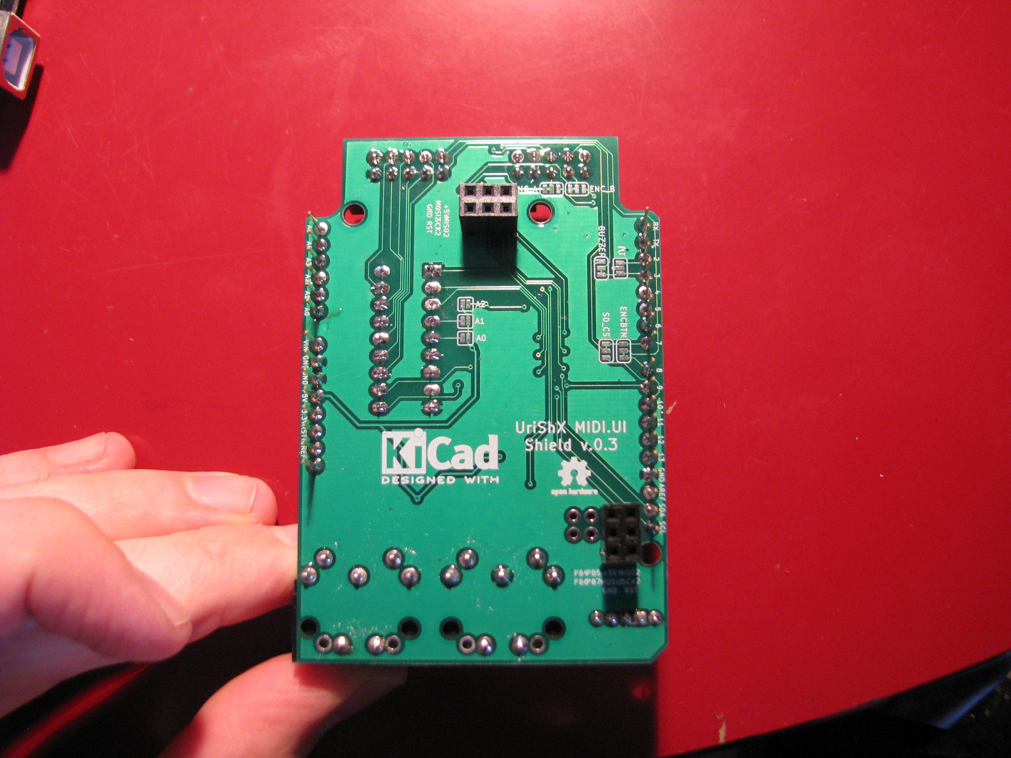
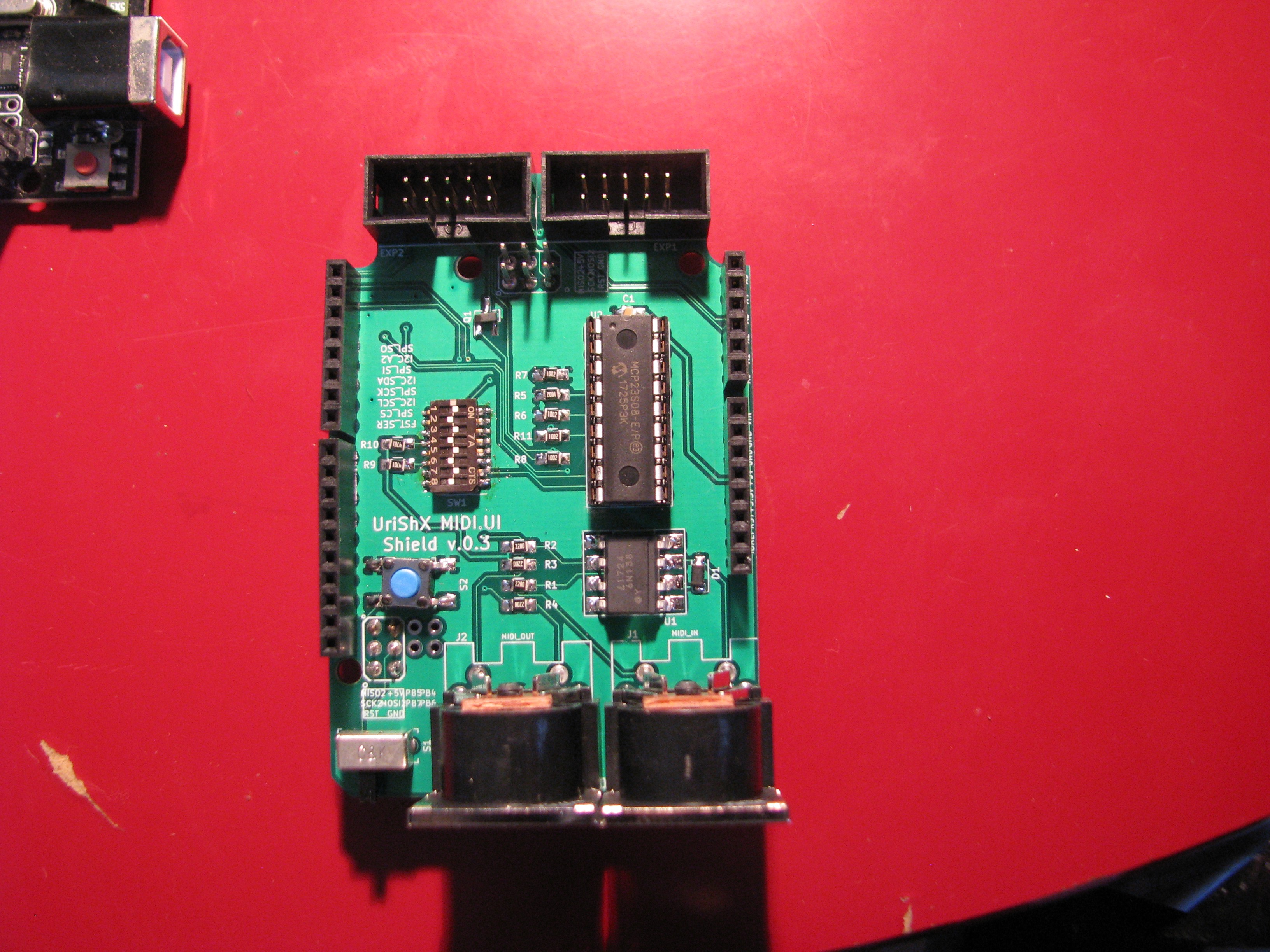
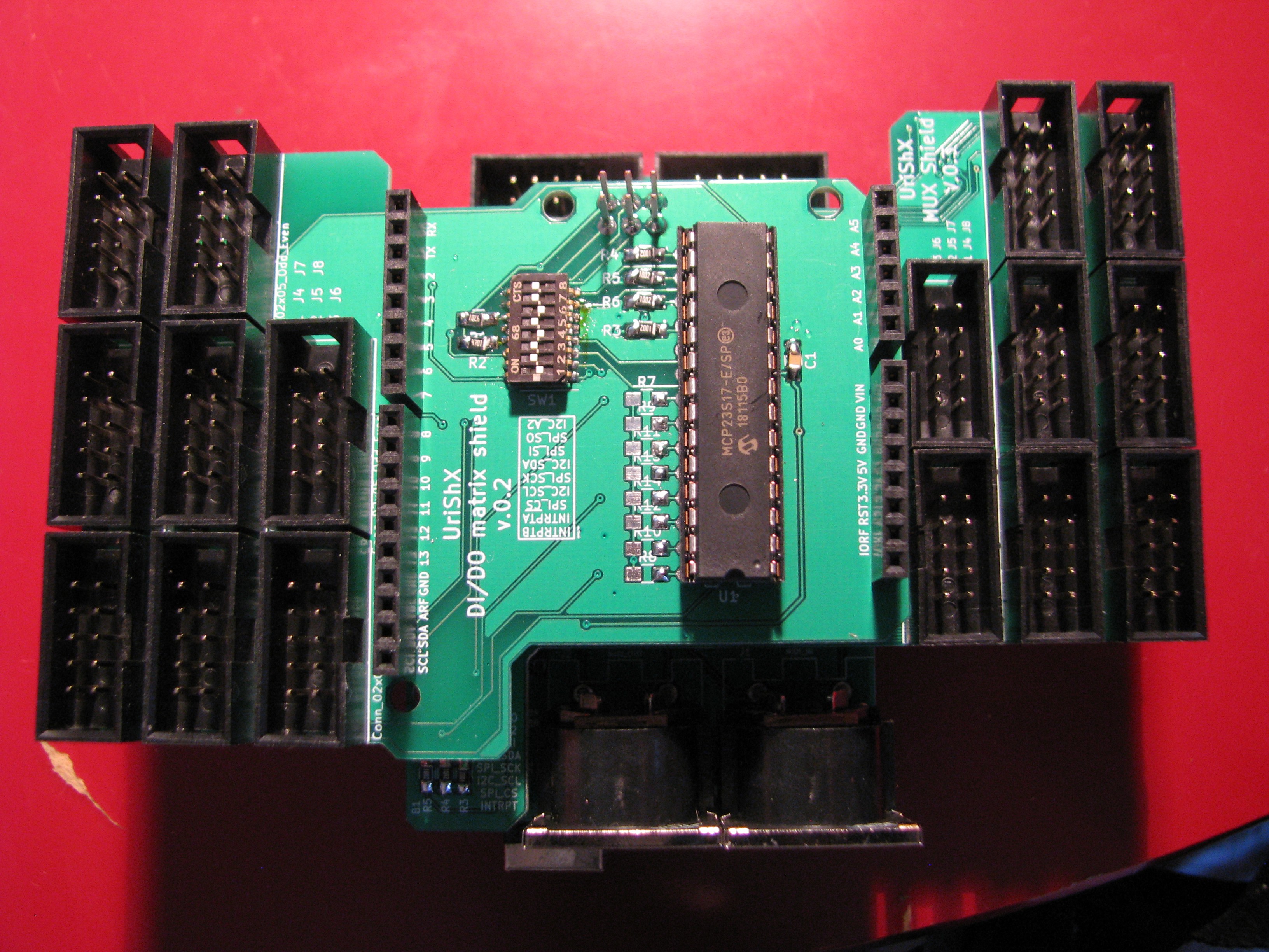
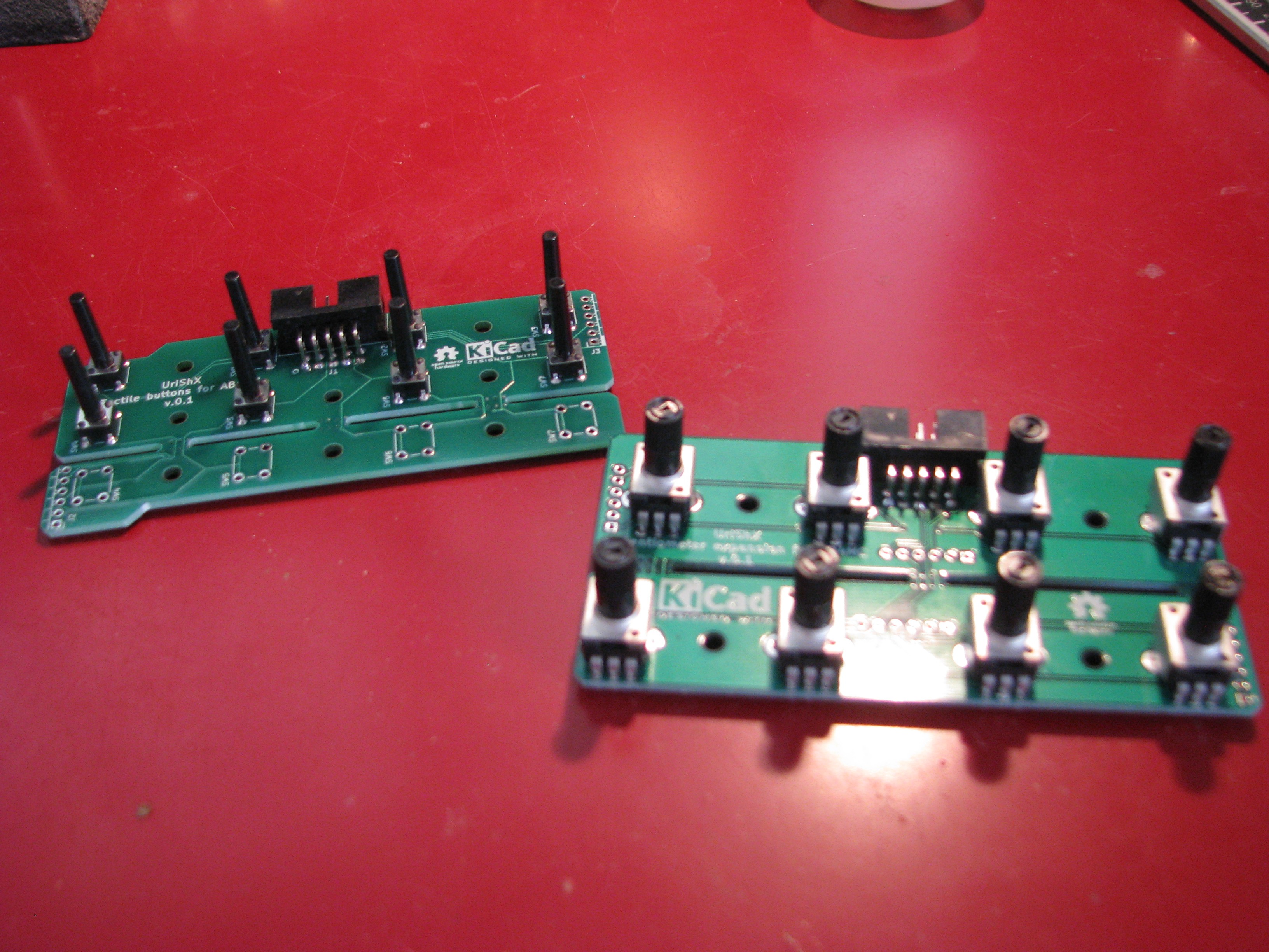
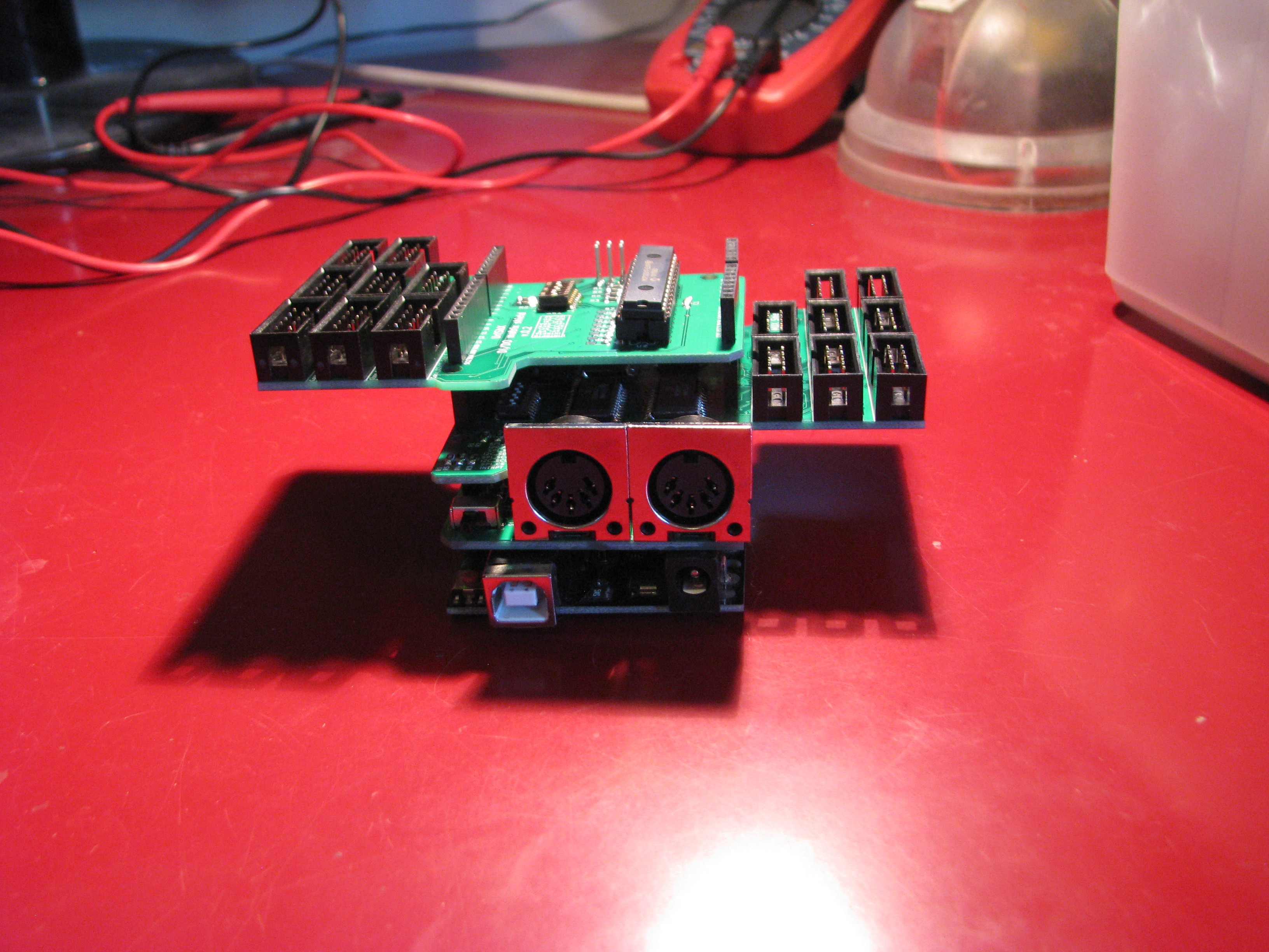
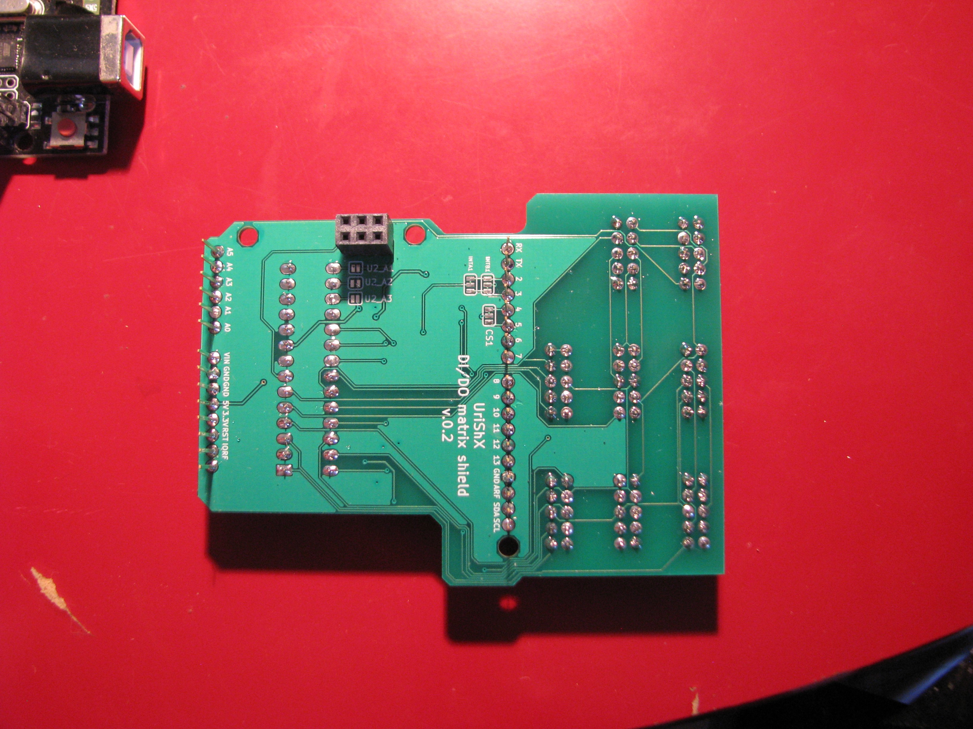
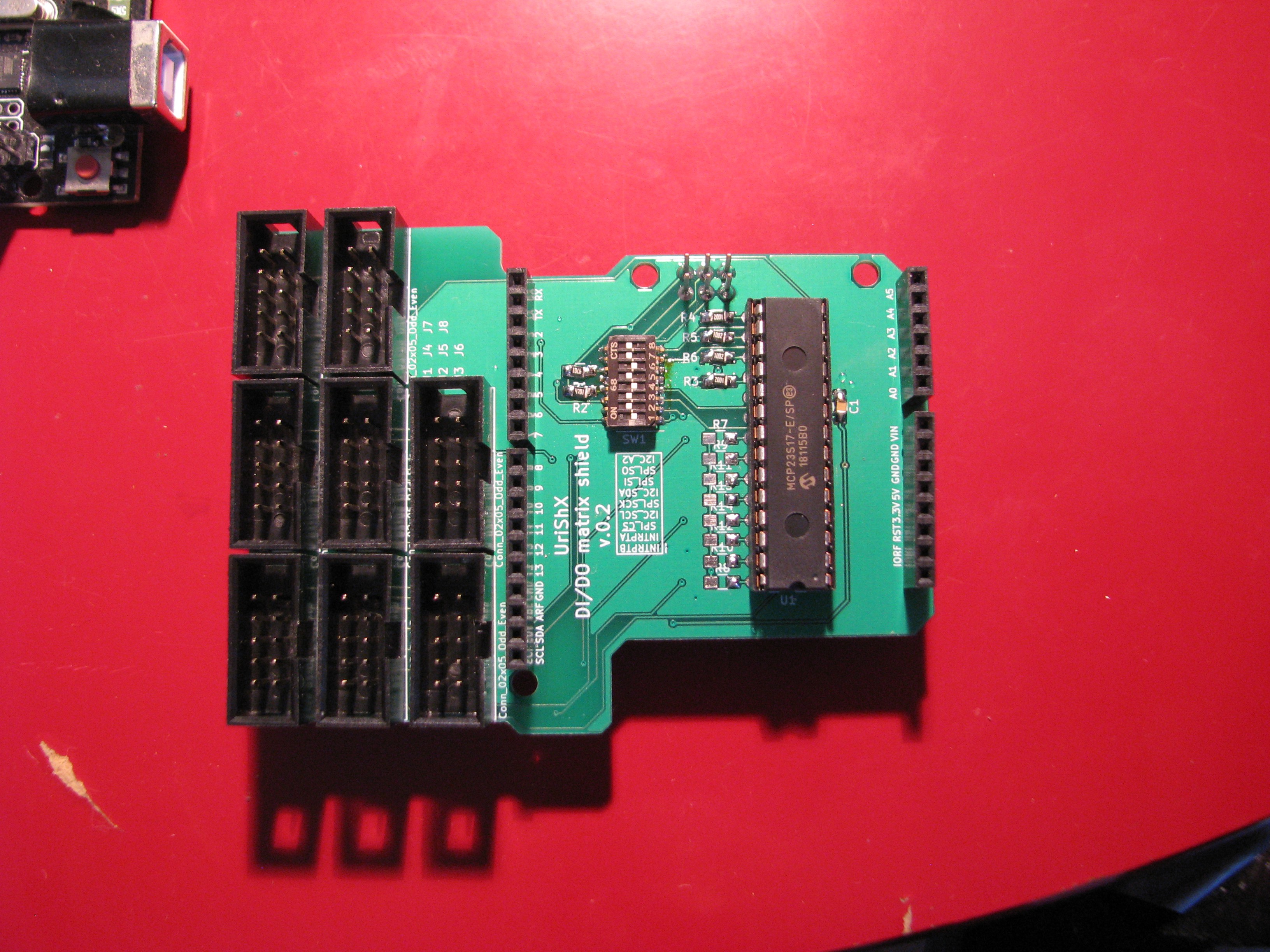
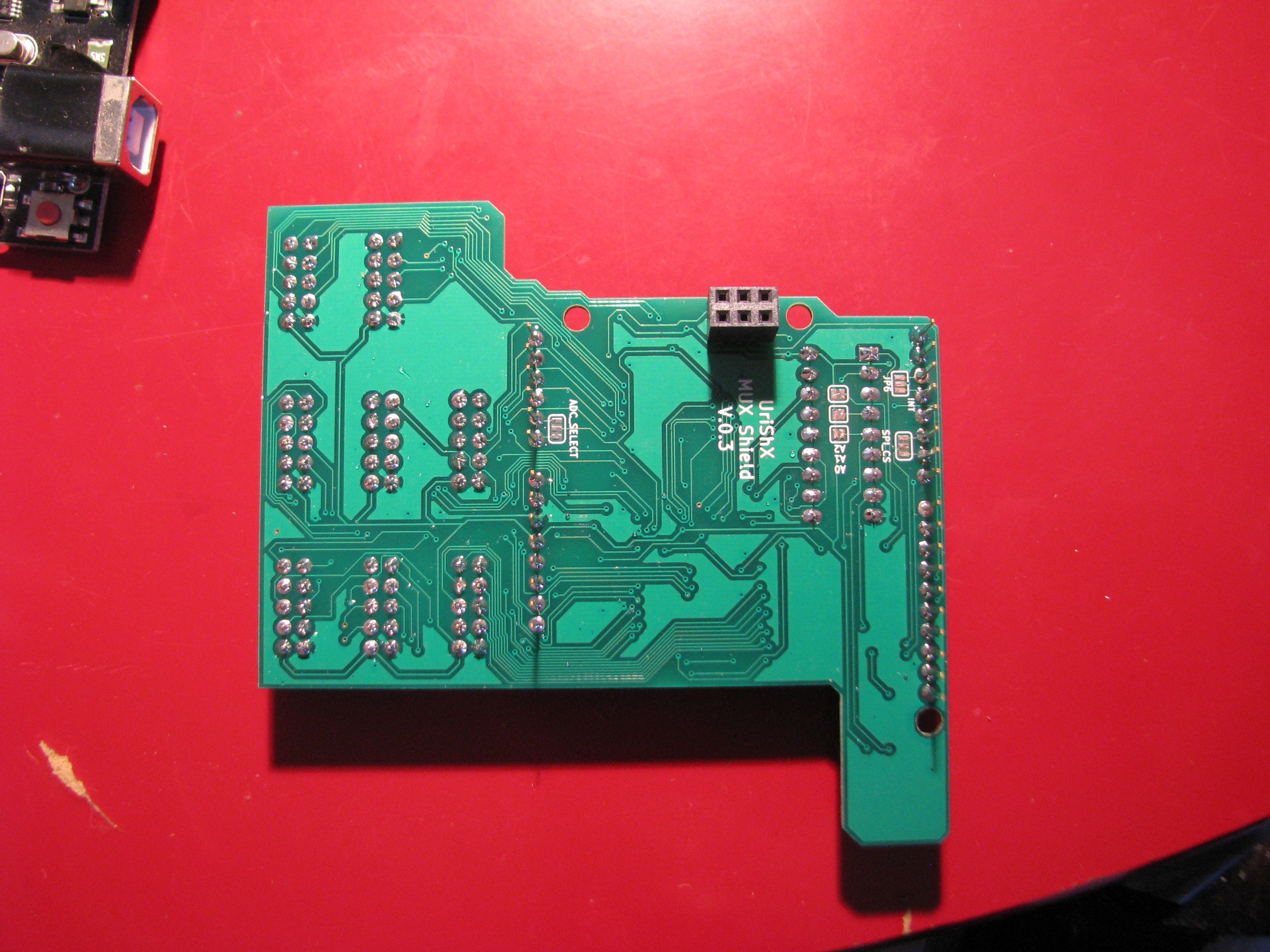
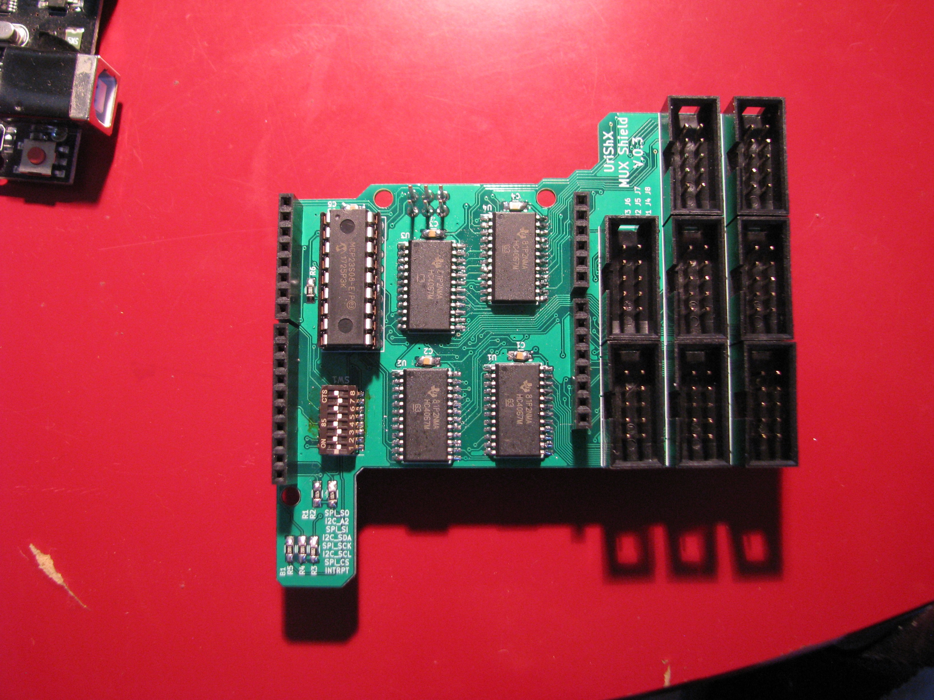
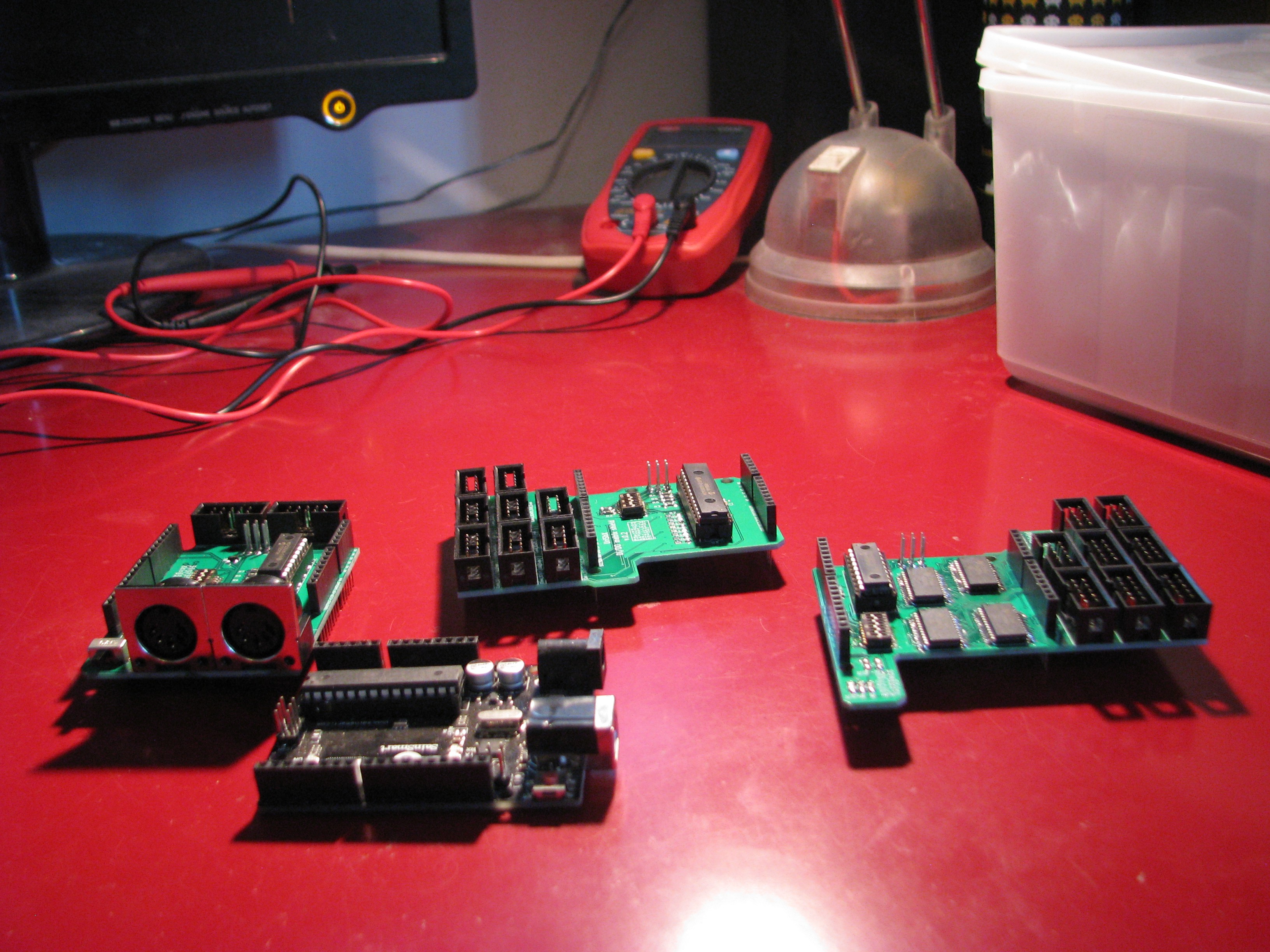
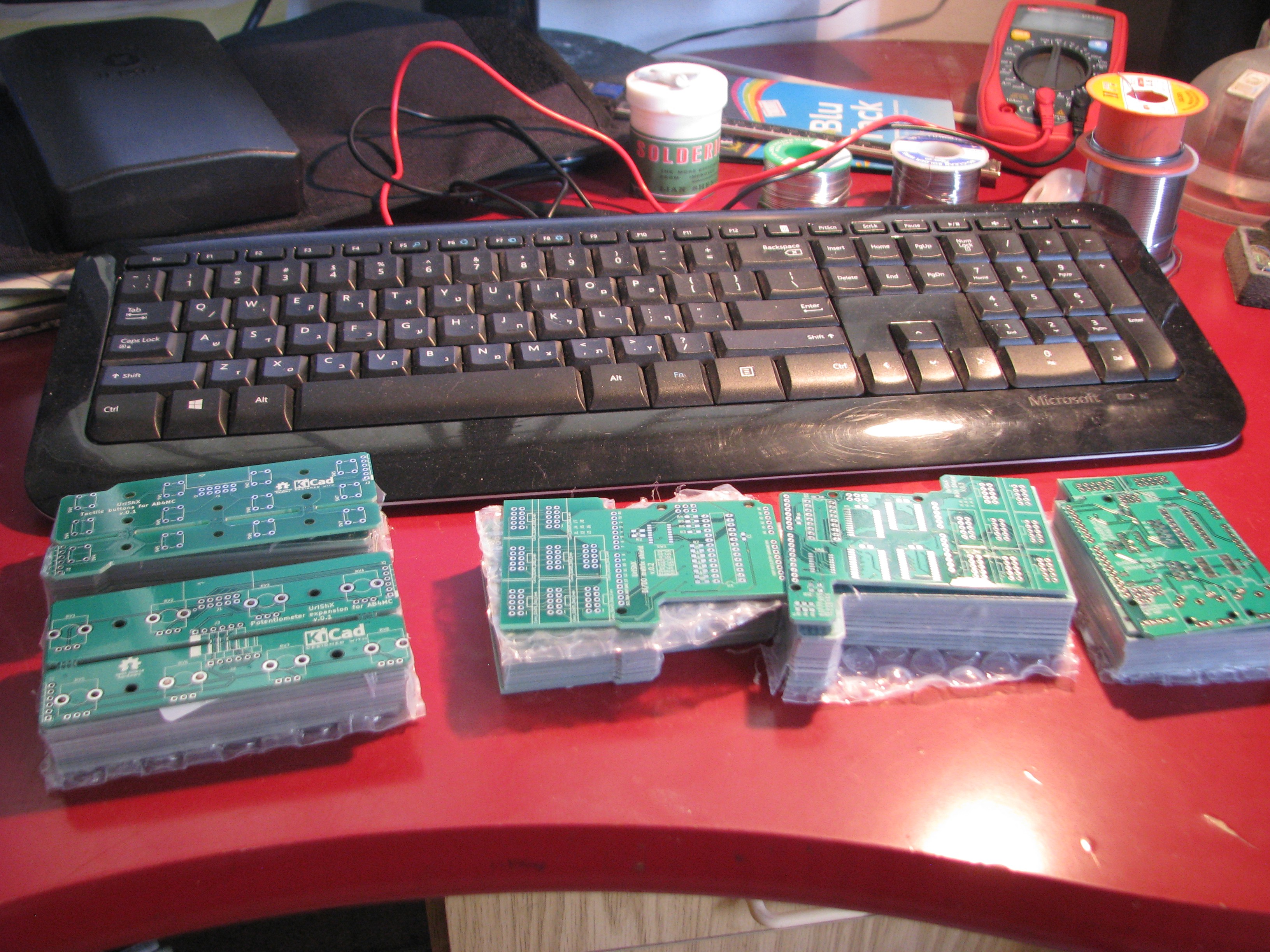
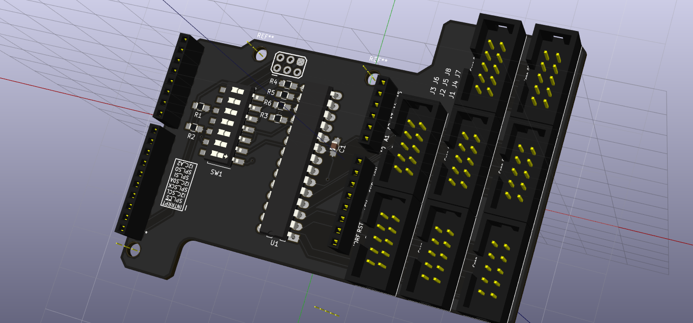
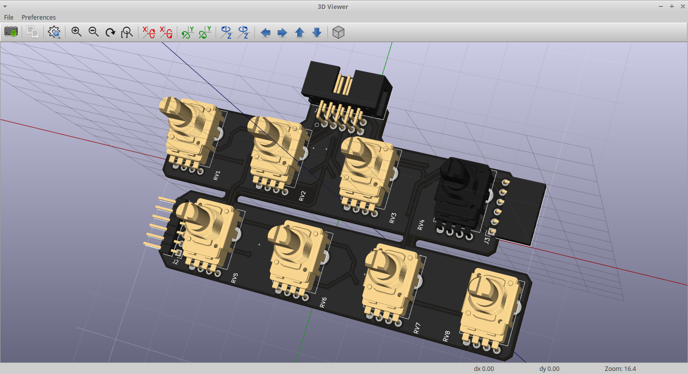
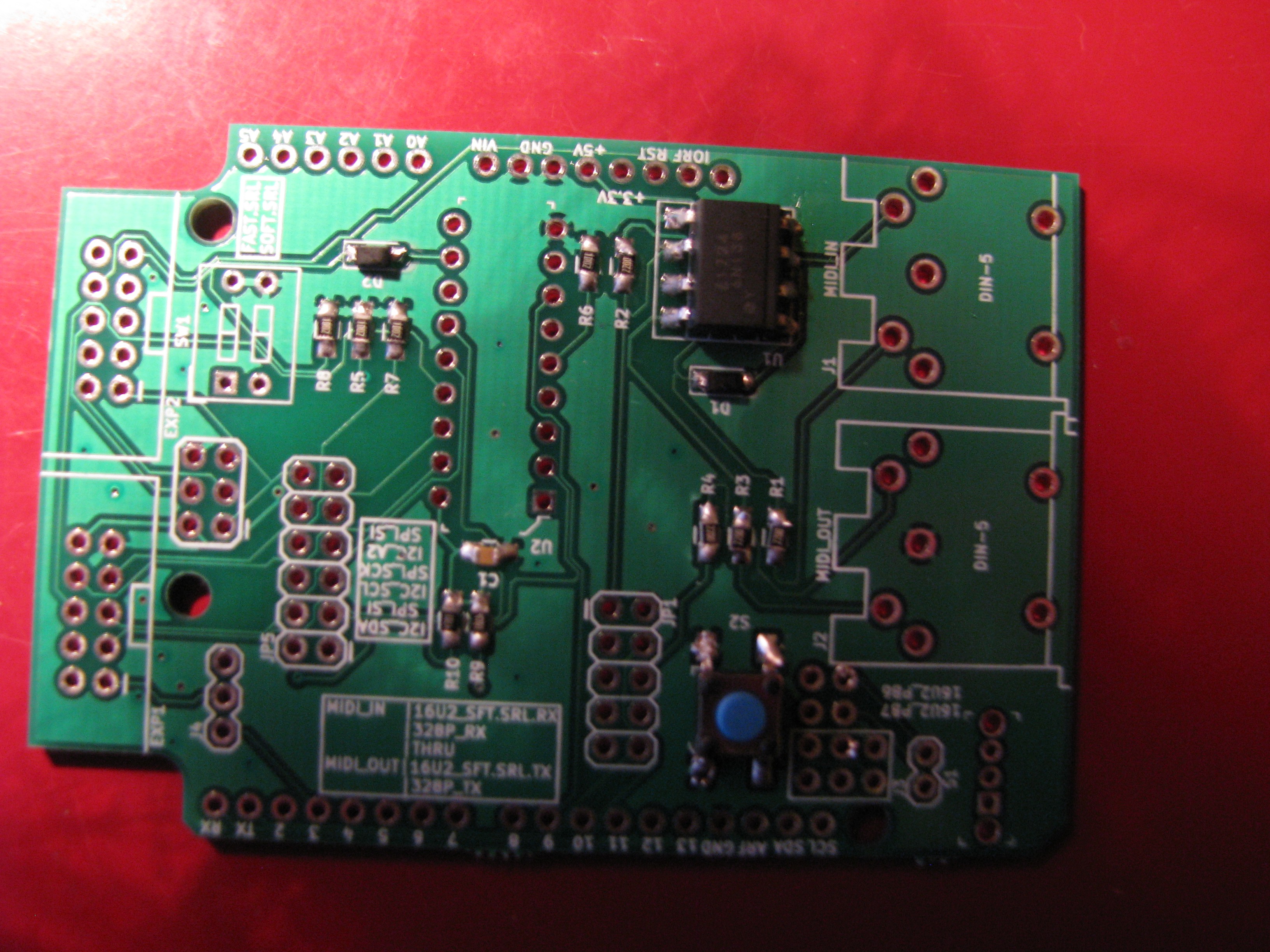
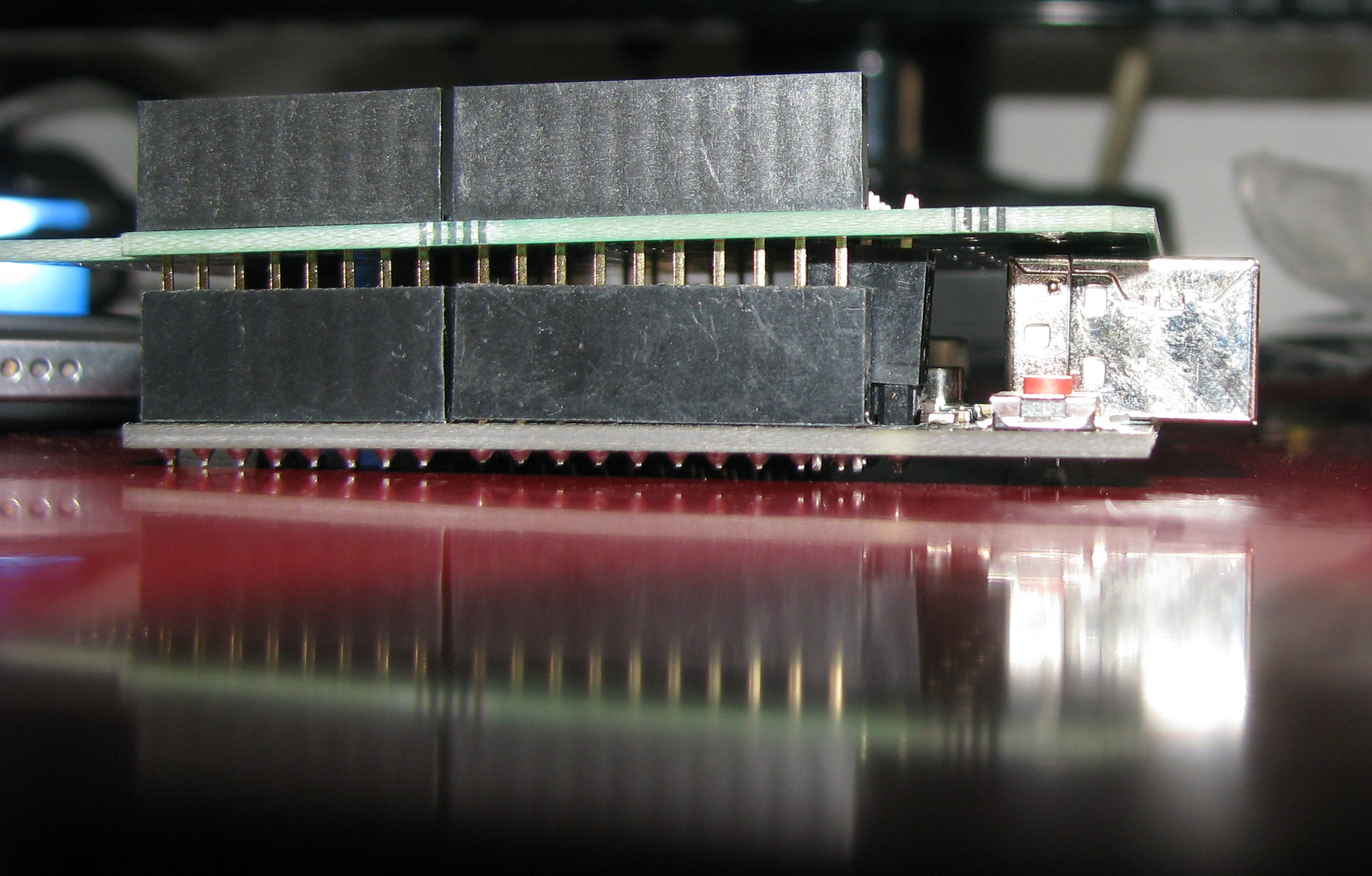
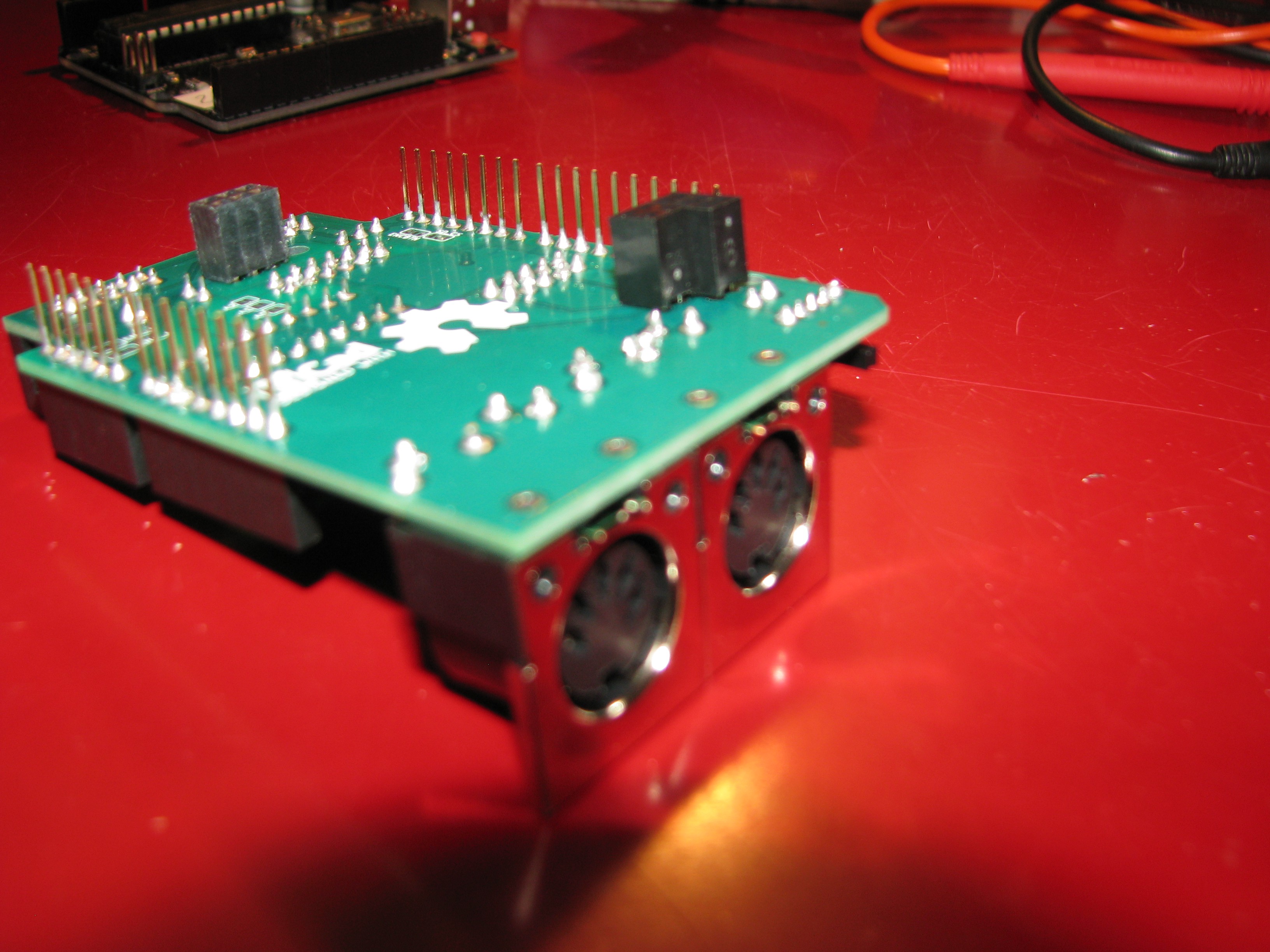
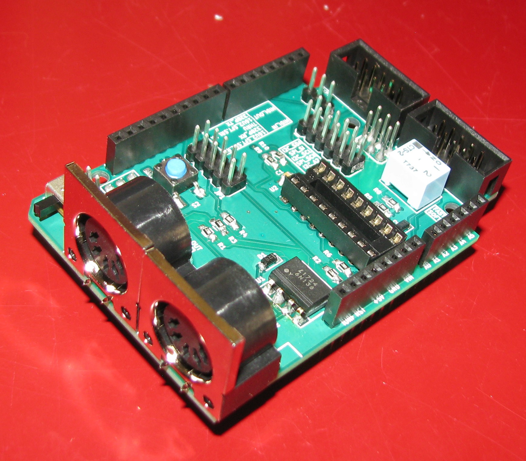
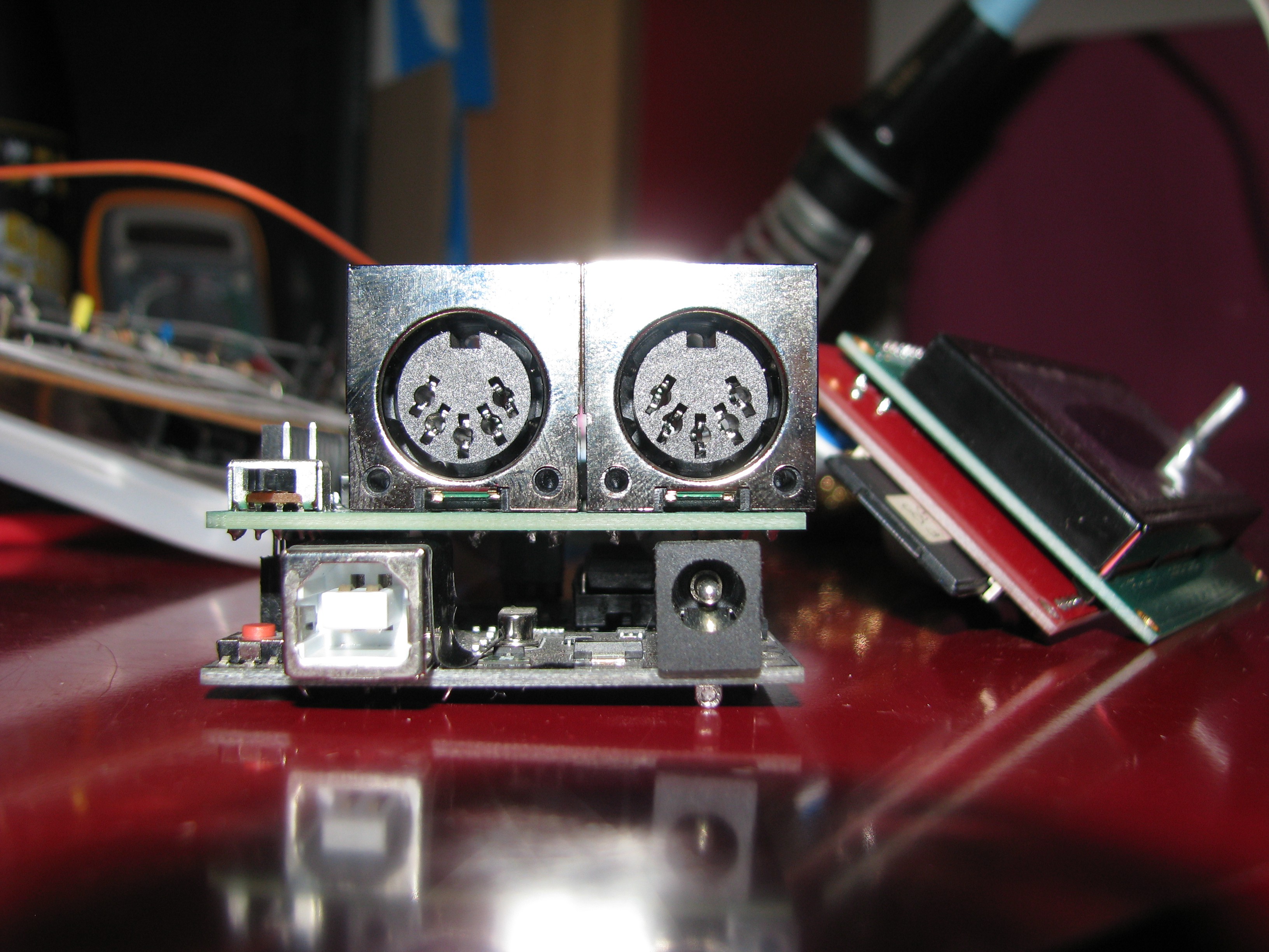
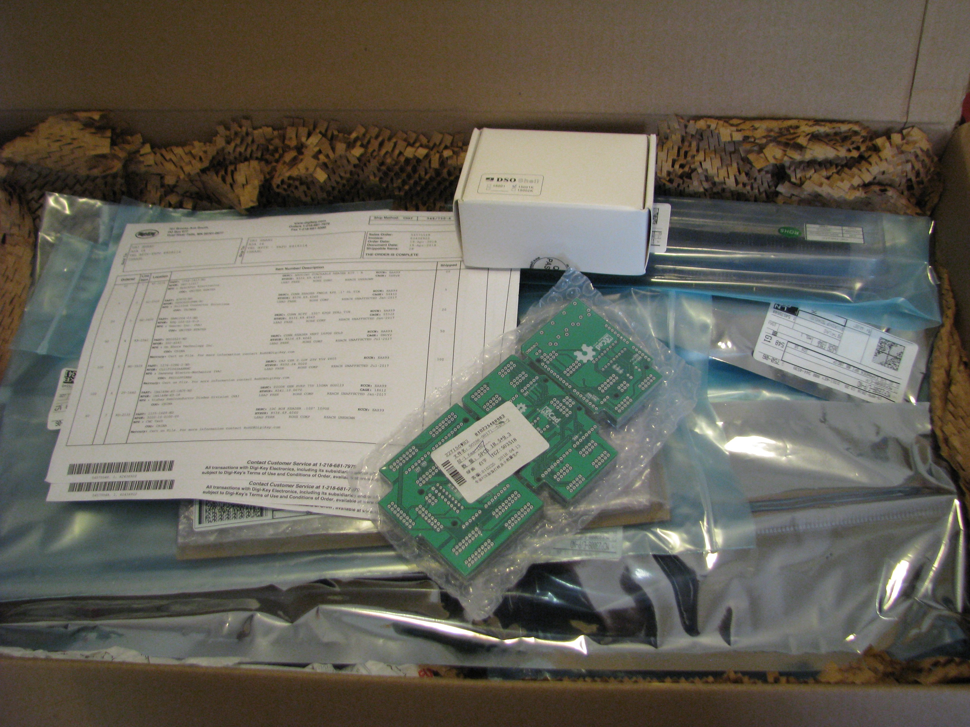
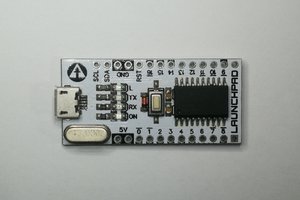
Edit 13/ 04/18: I just realized I didn't attribute my project's picture components. It's a collage of 3 pictures I got online - an Arduino Uno board pic which is CC-BY-2.0, a pic of ardublocks from a Hackaday article, and a picture of a Mackie control built with midibox by akorbety on flickr which is CC-BY-2.0. Pictures were resized and cropped, and by no means meant to suggest this is my own work. The two other pics I uploaded are a panel of the 3 boards I designed for the first stage of this project.
I wanted to make musical instruments since I was young. I wanted to make electric guitars. Then I wanted to make electric basses. That's what I was playing. Then I got to do some home recording, and got to know Pure Data - and I wanted to have a physical control for every MIDI event! Alas, it was 2004 or something, I was a musicology student with minimal technical background, and what I could find on the internet required skills I just did not want to learn at the time - such as coding, and understanding electronics to a higher degree than just hand soldering a new jack to my guitar. The project I found then was MIDIbox, which is still going strong today.
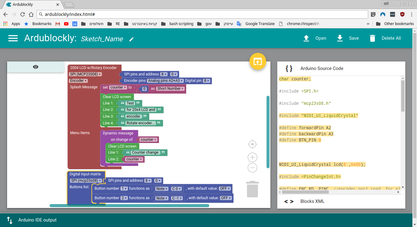
I still want to make my own "things". Mainly, I still want to make musical instruments. And throughout the years I got to know there are projects which may help make this endeavor more accessible to people who, like me of 14 years ago, don't really know where to begin and see the learning curve as too steep - projects like Arduino and Arduino shields, Ardublocks and other visual programming languages, and mocoLUFA which is a MIDI firmware for the Arduino Uno's USB chip. And I'm sure there are more. So, I think it's possible to lower the steepness of said learning curve for what I thought was just too daunting 14 years ago. I believe that by doing so, more people who would not consider designing their own physical interface.
I began working on some shield designs which will make it easier to quickly and easily allow one to prototype and actually make their own MIDI controller. These shields are meant to be accompanied by Ardublocks programming blocks for visually programming an Arduino Uno or Mega. This is still a future challenge for me. The whole thing is sort of a design challenge for myself, to design something my 14 years younger self would actually be able to use, and learn further concepts through. Essentially, this is both a learning goal for me, and a STEAM project for people who fear STEM education (or that just never got it).
I suppose that the main problem this project aims to solve is making technology more accessible to musicians who wish to create a computer / synth interface that is unique to them, as an extension to their own creativity and musicianship. In the broader sense, I believe this project aims to enable participation in technology creation and design not only for children, whilst lowering the entry requirements - or at least lowering the steepnes of the learning curve.
I put up a short survey in order to assess if the Venn diagram I have in my mind's eye is at all true. In my imaginary diagram, the overlap between artistic people and would-be hardware hackers is quite large, given that many sound making systems requires the creative person using them to link different elements in virtual or physical cables in order to produce the required result.
I would very much like the participation of as many creative people in this survey, be them technically inclined or not, in order to compare the results to my imaginary Venn diagram. If you are such a person, or know someone who is, please fill out (or forward) this short form.
Challenges facing me in this project are three-fold, as far as I can see at the moment:
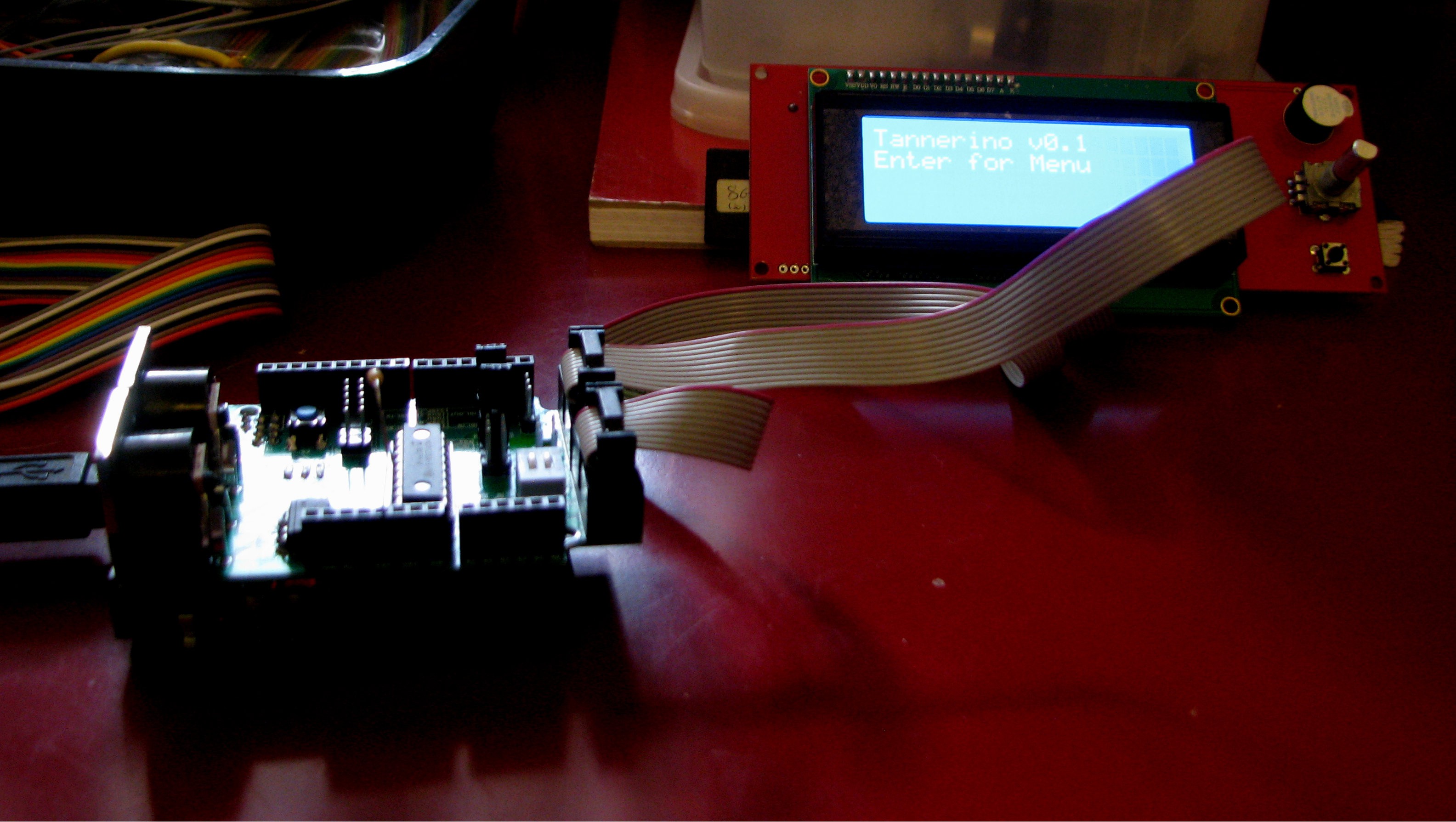
- I am not an electronics engineer, and don't know much about hardware design or writing code. I just know what I had to learn to accomplish my goals, and get my prototypes up and running.
- I am quite sure...


 Clyde D. Corpuz
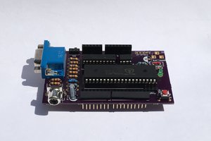
 Dylan Brophy
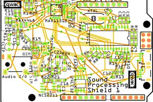
 bobgreenwade
 cb22
cb22