 M.daSilva
Right now, this device is built with two uses in mind:
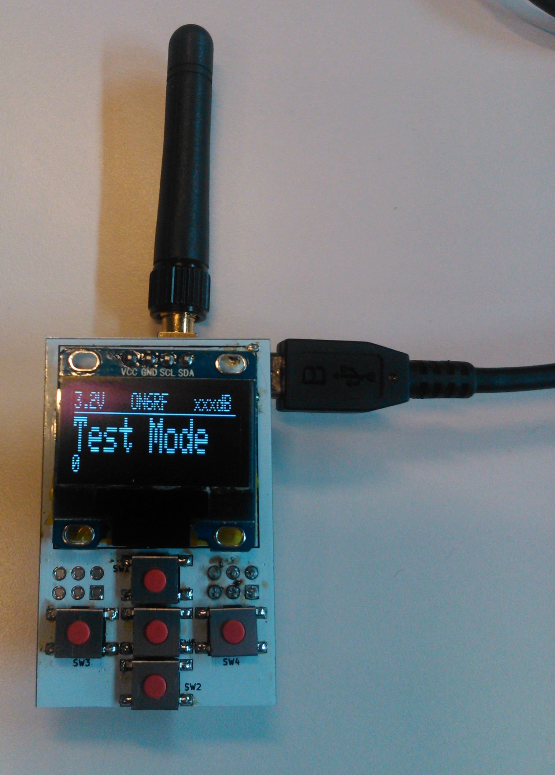
- Amateur Radio paging system. Something in the lines of a one-way system (for now): a base station made of a CC1101 plus a hefty power amp broadcasts messages over 70cm band to small modules people carry around. The small receivers include an LCD and buttons to display and acknowledge the messages.
- Digimodes interface: the CC1101 can transmit using 2FSK, 4FSK, GFSK, MSK, OOK and flexible ASK (as per the datasheet).I thought it would be interesting to make a small interface linking this module to a PC, and maybe add a small PA to bump up the power up to 7W. I never got into digimodes over UHF, this may be a chance to do so.I think non-amateurs may also use it as long as they don't use a PA and stay in the 433MHz band.
The uses can also be expanded for a more general public, for instance:
- For weather alerts
- For earthquake alerts
- ...?
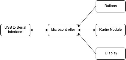
The following block diagram summarizes the inner configuration of the device:
- First ideas
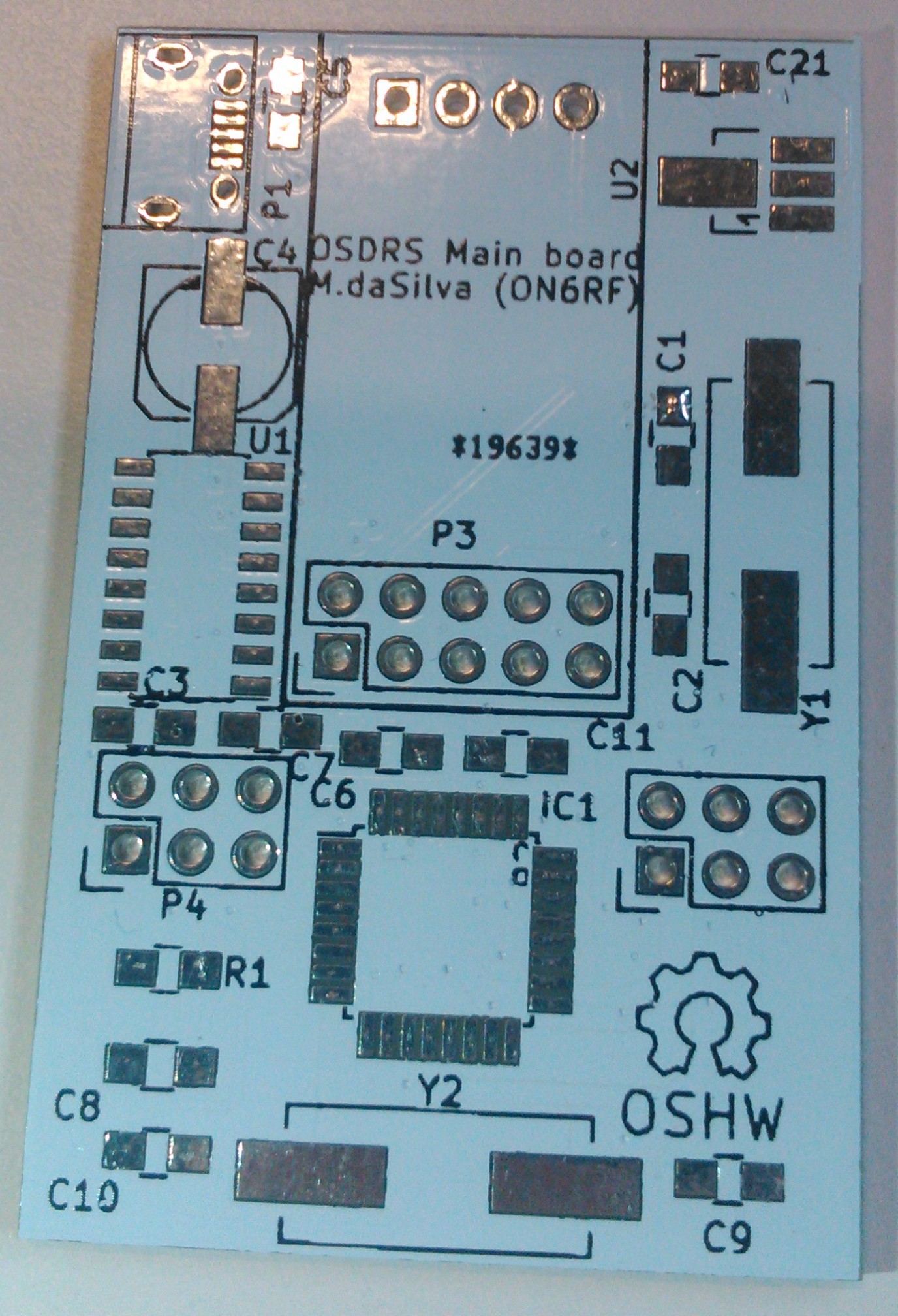
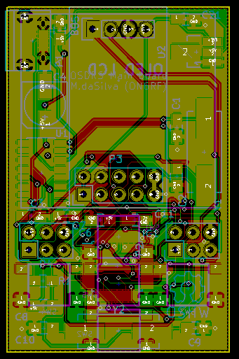
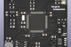
- Main board design
- PCBs
- Finding a correct name, other uses, parts coming in
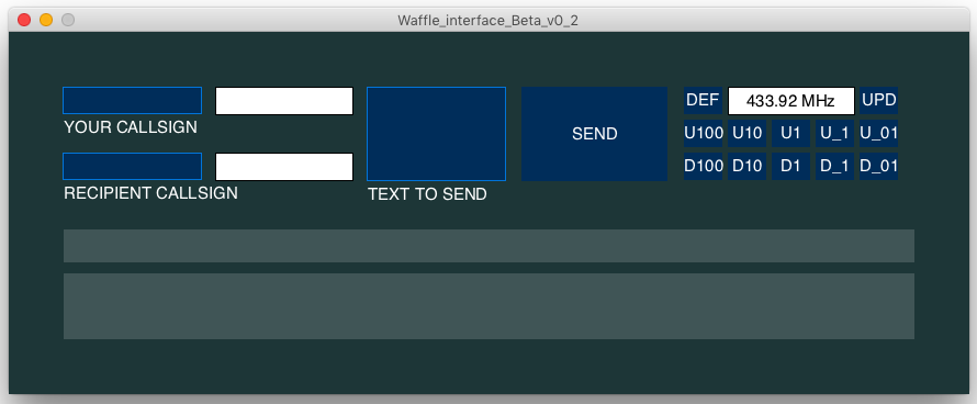
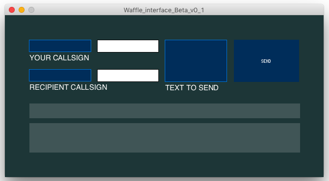
- Waffle Modem Computer Interface
- Building the dirtiest UHF antenna
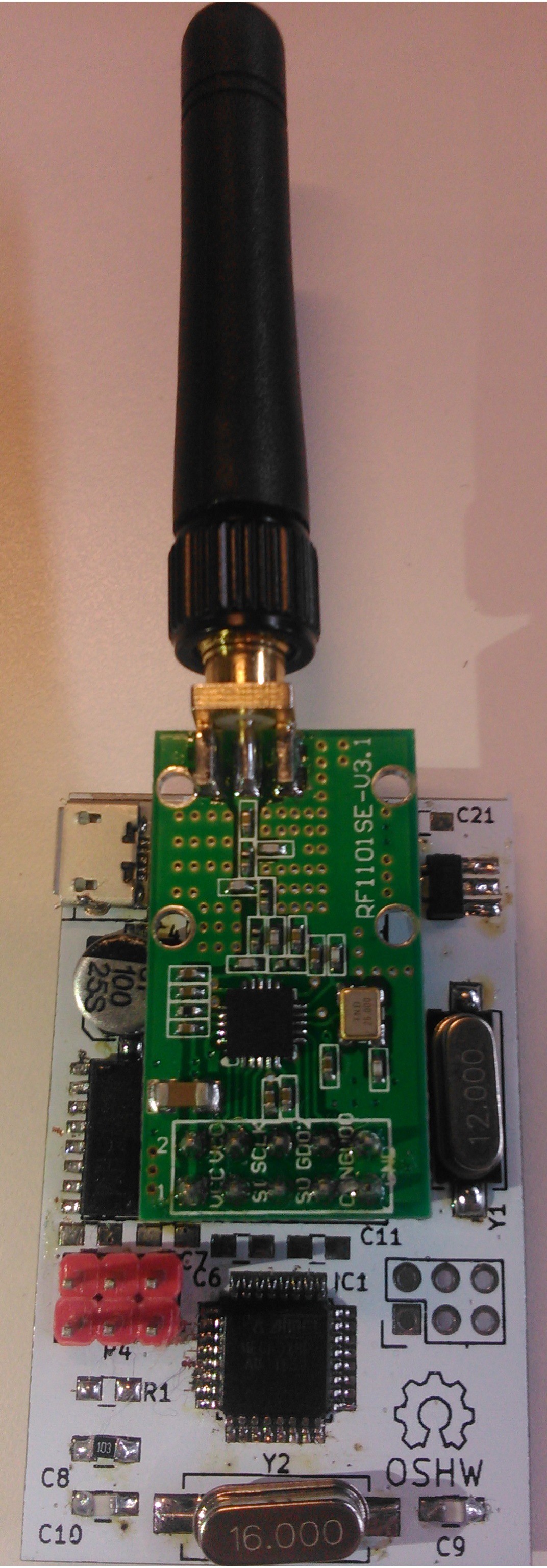
- First prototype
- Small progress for the Interface
- Wow, we were selected in the "Anything Goes" challenge!
- Proof of Concept
Why Waffle you may ask? Well, I like waffles, it's a catchy word, and I've always wanted to name one of my projects after food. My friend @Frédéric Druppel found a matching abbreviation for it: Wireless And Free Format Lite Emitter. Feel free to find another that matches the project's name :)
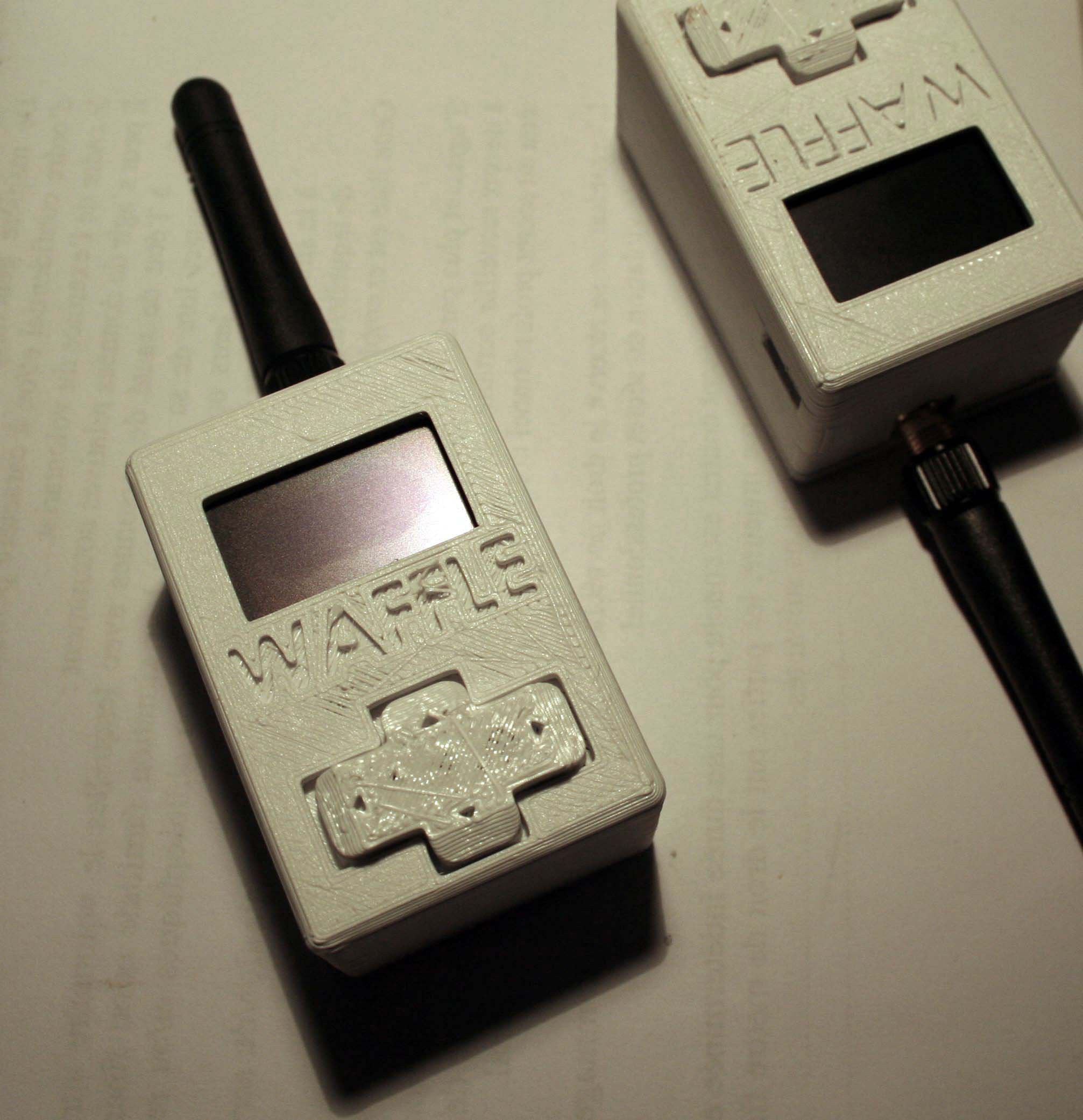
 I used brass for the radiating element and the radials. They're a bit sturdier than copper, though I don't know how it affects performance.... It can't be worse than those stainless steel whips! The antenna was brought to a 1:1 SWR match using an antenna analyser, by trimming the antenna with a pair of pliers.
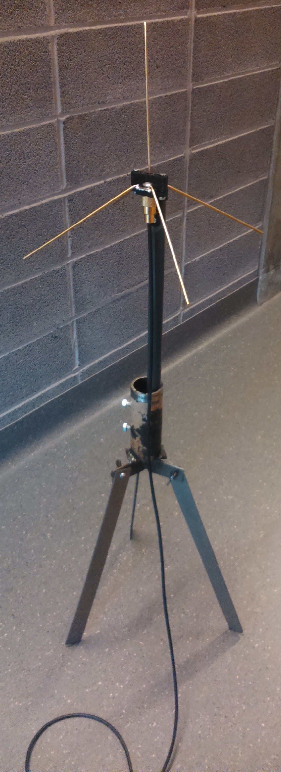


 Matias N.
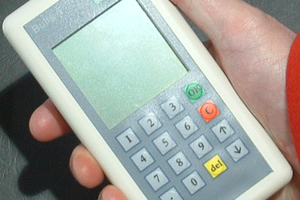
 Boz
Boz
 daniel.bryand
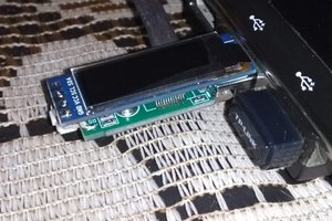
can You add https://reticulum.network/index_pl.html to this system?