 Aron Molnar
2016 Hackaday Prize entry video:
There are two functioning models right now:
- The linear sensor (hereinafter referred to as Linear FCDT) that has the proper geometry (Length/Radius) ratio can measure tilt in a 40 degrees interval and has a relatively good resolution.
- The circle-like sensor (hereinafter to as Toroid FCDT) that has the proper geometry can measure tilt in a 360 degrees interval.
There is a little demonstration video of the circle-like sensor in working:
(In this video, the sensors' signal conditioners' (Analog Devices AD598) output is measured with a multimeter, and the measured values are sent to a laptop via RS-232 serial port. Then a LabVIEW program calculates the tilt based on the sensors' characteristic, and indicates it.)
The idea
First, let's imagine three coils placed next to each other. The middle coil is called the primary coil, and the two on the sides are called the secondary coils. Let's place an iron core into the coils' air gap, and excite the primary coil with an AC signal (normally with a sine wave). Now, what will happen? Well, it's basically functioning like a transformer, so depending on the iron cores' position different voltages are being induced in the secondary coils. Then, if I move the iron core, the induced voltages in the secondary coils are changing. With the proper signal conditioning circuit, I made a linear displacement sensor! (By the way, these machines are called LVDTs - Linear Variable Differential Transformers, and are widely used in industry.) There's an awesome website where there is a more awesome simulation about the working of an LVDT: http://www.rdpe.com/ex/hiw-lvdt.htm
Cool. Now, you'd probably heard about what ferrofluid is (if don't: https://www.youtube.com/watch?v=5APHa7vscoI). Ferrofluid is a ferromagnetic fluid which contains nanoparticles of metal, that's why it's being attracted by magnets, and basically functioning like "liquid metal".
The basic idea is that what would happen if you'd remove the LVDT's iron core and replace it with a ferrofluid filled glass tube. Somehow like this:
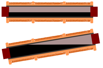
Well, the ferrofluid would act like the replaced iron core, and as you tilt the sensor, the induced voltages in the secondary coils would change depending on the tilt, so you'd make a tilt sensor!
Linear FCDT
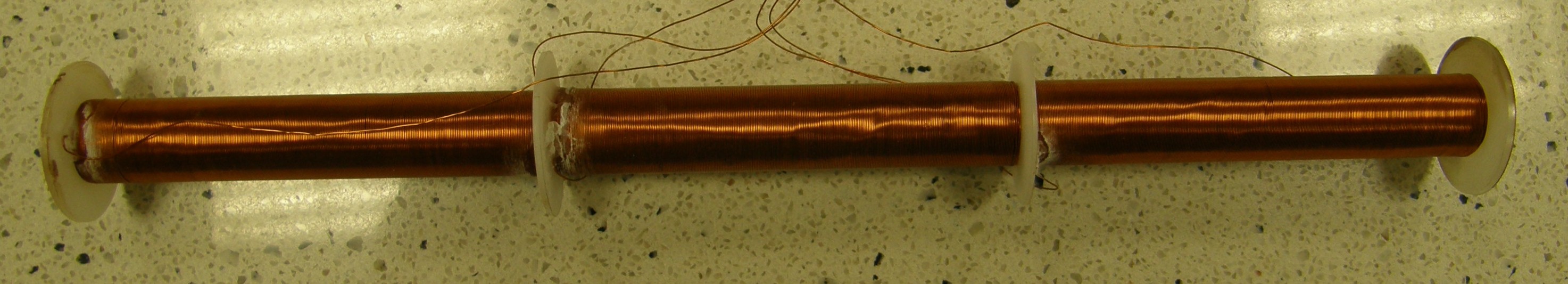
And that's it. That's the basic concept behind the sensor. I call this arrangement the Linear FCDT(Linear - the coils placed "linearly next to each other; FCDT - Ferrofluid Core Differential Transformer)
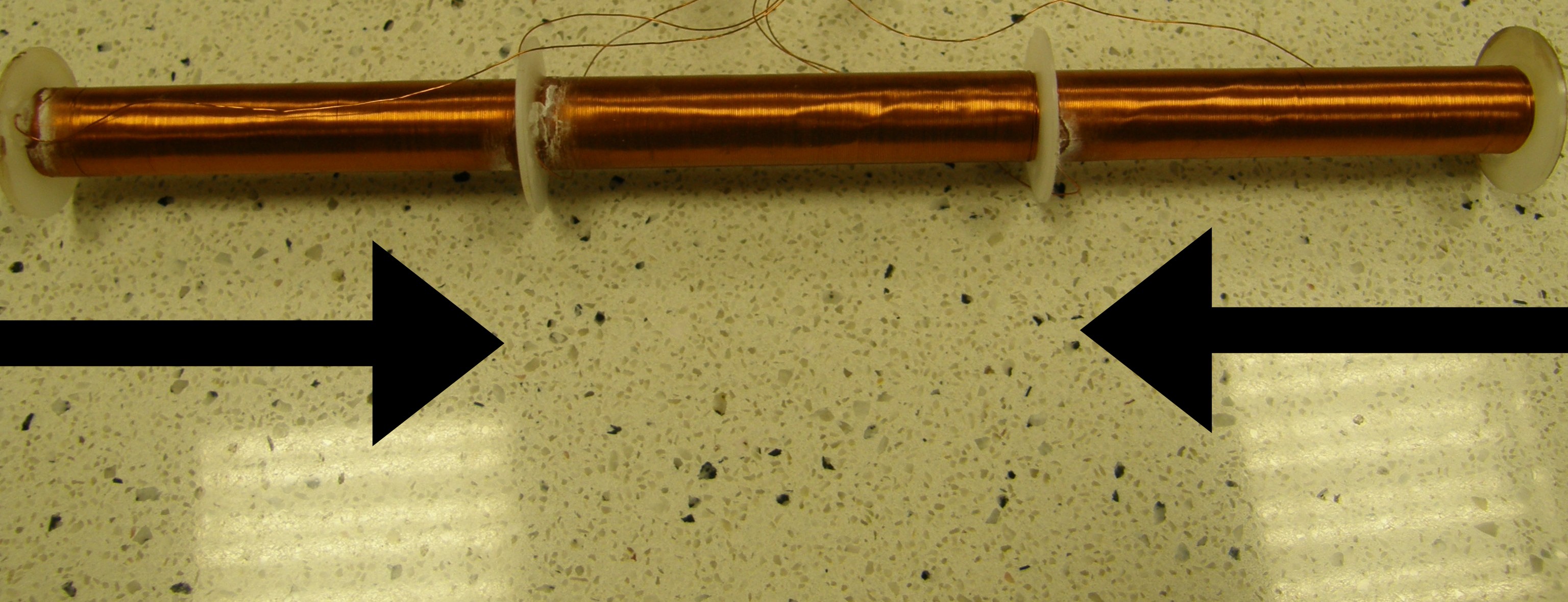
Our next task is to make experiments with it. First, we'd like to know what is the maximum value of tilt it can measure. Based on experiments I made - as I mentioned earlier - it's a +/- 20 degrees interval. Why? Well, if you reach a specific state of tilt, the ferrofluid runs out from the air gap of one of the secondary coils, like this:
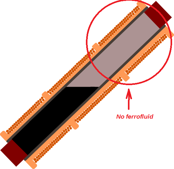
Thus, there won't be generated any voltage in that secondary coil (or the generated voltage would be insignificant), so the sensor's output voltage will deteriorate.
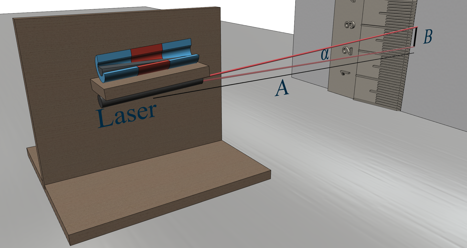
Our next thing to do is to make a sensor which can measure in a larger range, but first, let's measure the accuracy of this arrangement! After hours and hours of making an extremely precise measurement, I came up with this diagram:
(How the precise resolution measurements were made: https://hackaday.io/project/11225-a-new-high-accuracy-tilt-sensor/log/46066-how-the-precise-resolution-measurements-were-made) 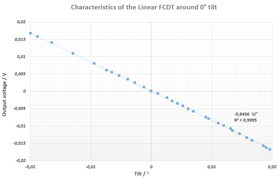
Theoretical background of the Linear FCDT: https://hackaday.io/project/11225-a-new-high-accuracy-tilt-sensor/log/46957-theoretical-background-of-the-linear-fcdt
Toroid FCDT
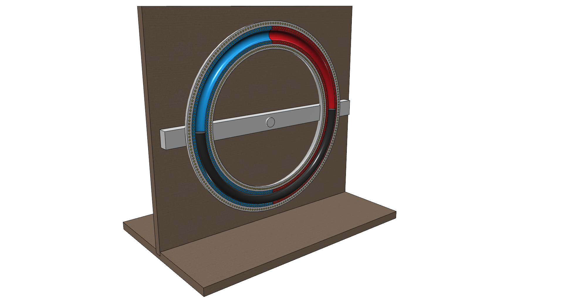
So, if we would like to have a greater measuring range than 40 degrees, we'd have to redesign the whole sensor. The problem with the Linear FCDT was that the ferrofluid ran out from one of it's secondary coils after reaching + or - 20 degrees of tilt. What if we bend a glass tube like a circle, fill it half with ferrofluid, and turn the coils around it toroid-like (hence Toroid FCDT) with the secondaries...
Read more »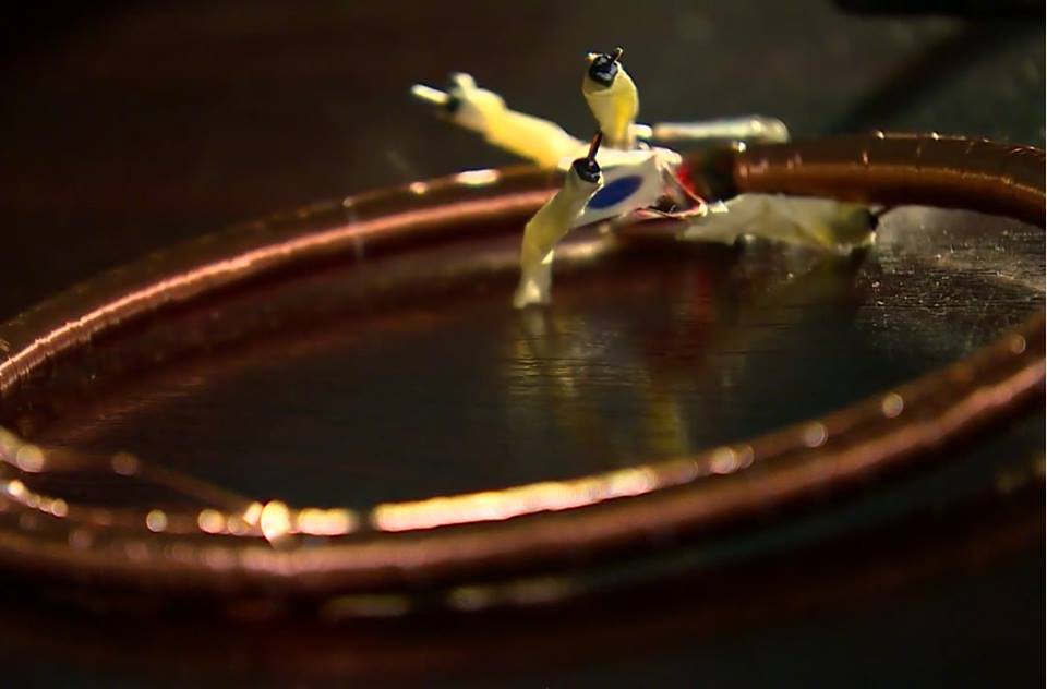
 To get reliable data from the sensor, we have to take it to a very massive and vibration-free place and make measurements with it for at least 3 days in a row. We found the proper place at the University of Pannonia on top of a high-tech CNC machine. To make it convenient, I made a little program in LabVIEW that sends the measured data to my email address at every 12th hour for 3 days (the program's VI can be found in 'Files' section).
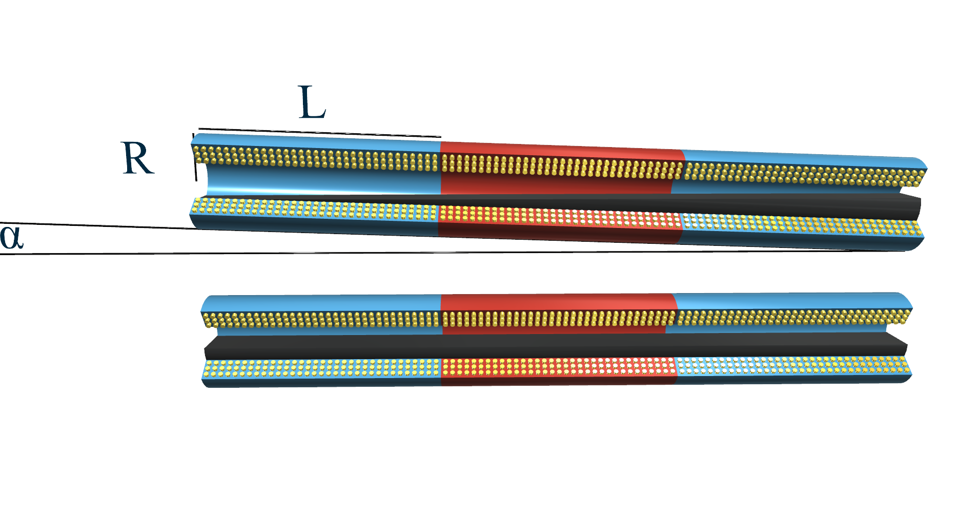
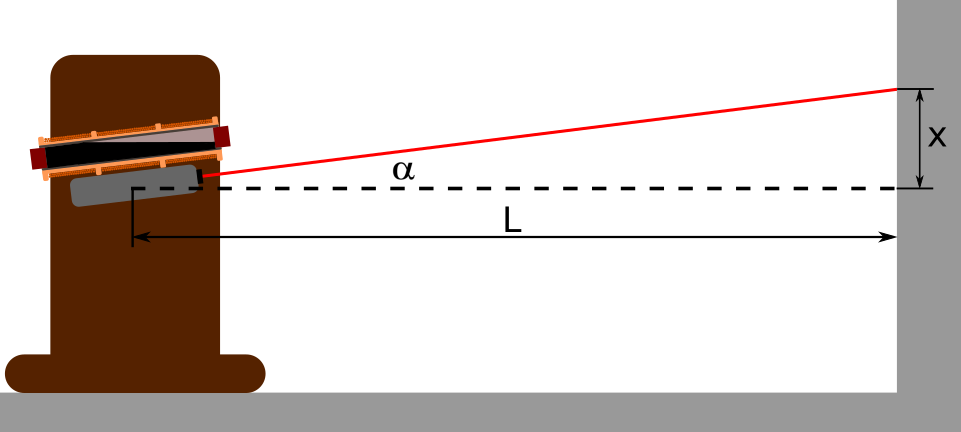
 First, we need to slice the sensor at a point, and calculate the area of the ferrofluid at that point. This area should only depend on values we already know, such as the alfa tilt degree, the L coil length, the R radius, and the x variable. If got the area at that point, we can integrate it along x, and we get the volume of the ferrofluid.
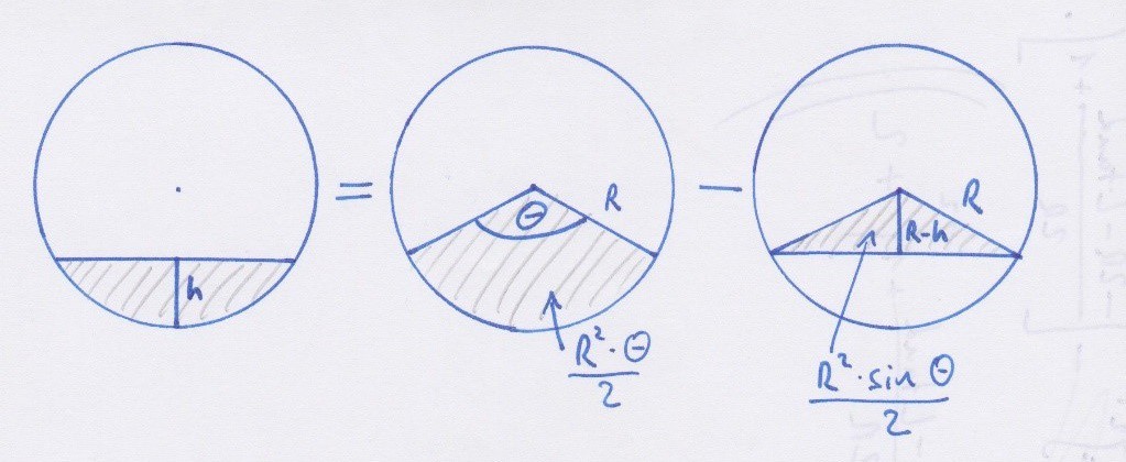
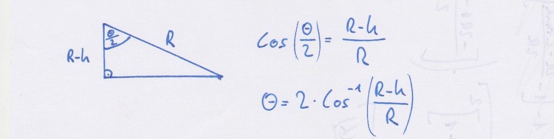 With this, the formula of the area looks like this:
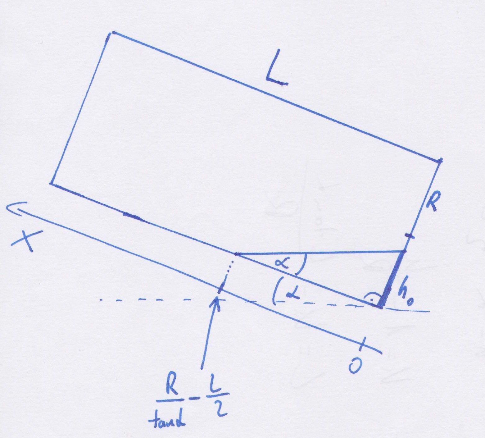


 Bud Bennett
 jaromir.sukuba
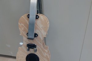
 Minimum Effective Dose
Aron,
If you have data from your Moon tracking experiment, I can compare it to the sun moon tidal acceleration signal I use to calibrate superconducting gravimeters (SGs) and three axis broadband seismometers. The sun moon signal is extremely complex and geometry dependent. It is nearly impossible to game. If you get it right, you only need a linear regression on each axis to calibrate your instrument as a sun moon gravimeter.
I will try to put some software on GitHub to generate the signal at a location. If you have breaks in the data, noise, earthquakes, it doesn't much affect the calibration. I have experimented with continuous random calibration that can be added to a small computer connected to the device. It probably can run on a Raspberry Pi or a clone.
About 95% of the signal at an SG station is the sun moon tidal acceleration. After you subtract the sun moon signal, that removes most of the earth tides but leaves all the rest of earth-based data, including the seismic data. And its associated gravitational early warning signals.
The SGs are so precise. But only vertical data. If they were three axis, you can solve for the position and orientation. An alternative to GPS, based on gravity. I had to learn to solve for orientation because portable instruments are not always set aligned to the earth's reference frame. It only works for permanent stations and long term observatories.
I suggest decimating the signal to one minute. That will give you a boost in precision, and it is easier to do a quick round calibration. That is 1440 readings per day, and quite satisfactory for an initial look over a few weeks of data. I have run one second data from the SG and seismometer stations, so if you have it, that is pretty easy to handle, and is the common standard for many geophysical networks. For early warning, you have to use arrays of correlated sensors to build up an image of the source. Starting with three axis from the beginning allows each instrument to determine direction. That might be enough to give single station warning of magnitude and direction. If gravity is not refracted at high frequencies, then it should be geometric line of sight to the disturbance. LIGO has some people who are very good with these kinds of things, but their heads are somewhere out there in the universe right now.
What you have done is something I need to study before I can see how it compares to others, and to see how it might be optimized for specific markets and tasks. I am just getting familiar with HackaDay.IO, but something(s) seem to be missing.
Richard Collins, The Internet Foundation