-
H-Bridge Circuit!
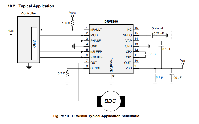
04/30/2018 at 12:04 • 0 commentsSo for the StepDC I chose the Ti DRV8801 H-bridge chip. It can handle up to 36V at up to 2.8A and it has built in overcurrent protection and monitoring. I chose this chip because it has a wide voltage range and supports a decent amount of current. While the driver can handle up to 36V I designed the circuit to be safe for 24V since components ruggedized for 36V would increase the cost a bit.
Anyways here is the reference schematic from the datasheet:
I'll be using these components:
https://www.digikey.com/product-detail/en/texas-instruments/DRV8801RTYR/296-23638-1-ND/1919072
https://www.digikey.com/product-detail/en/tdk-corporation/CGA5L2C0G1H104J160AA/445-6984-1-ND/2673002
Next off is doing some component footprint creation and laying out the schematic!!
-
Introducing StepDC
04/29/2018 at 13:34 • 0 commentsStepDC is a simple board that contains an ARM Cortex M4 microcontroller and a H-bridge. StepDC converts stepper motor driver signals (Step, direction, enable, etc) into PWM and direction to drive a DC motor with the h-bridg. This will allow users to easily replace stepper motors with DC motors and encoders. The ARM on baord is responsible for running a PID control loop to drive the DC motor with the h-bridge using the encoder as feedback.
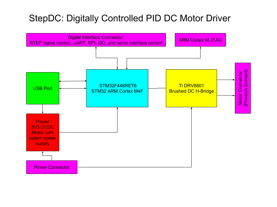
The hardware breakdown is simple for StepDC:
- STM32F446RET6 ARM Cortex M4 MCU
- Ti DRV8801 H-Bridge 8V-38V 2.8A
- Ti DCDC regulator of some variety
- Robust Phoenix contact connector for motor
- 2.54mm shrouded header for signals
- In addition to STEP signals UART, SPI, I2C, and servo PWM interface will all be available on the same connector.
![]()
Above is a block diagram showing how all these components interface with one another to make up the described system. Its relatively simple, 3 ICs, connectors, and passives. One thing I should note is that I decided to include more than STEP signal control for the digital interface, so on the same connector, UART, SPI, and a PWM servo style interface will be available. This makes StepDC more than just a stepper motor replacement board, its now a universal closed loop DC motor driver with many digital interfaces, oh did I mention it will also have USB for PC based projects!
The reason to expand the feature set beyond stepper motor replacement comes from my background in robotics. Back in the day I attend WPI and studied Robotics Engineering so robotics and systems engineering are my thing. I wanted to exapnd the feature set to get back to my roots in robotics and the plan is to use StepDC on many robot based projects in the future! Also I just could not resist the robotics challenge so consider StepDC entered!
Stay tuned for more!! Next up I'm choosing components for the PCB!
 AVR
AVR
