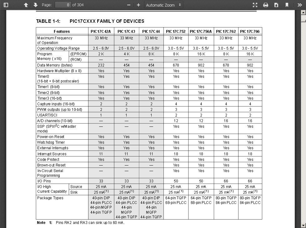
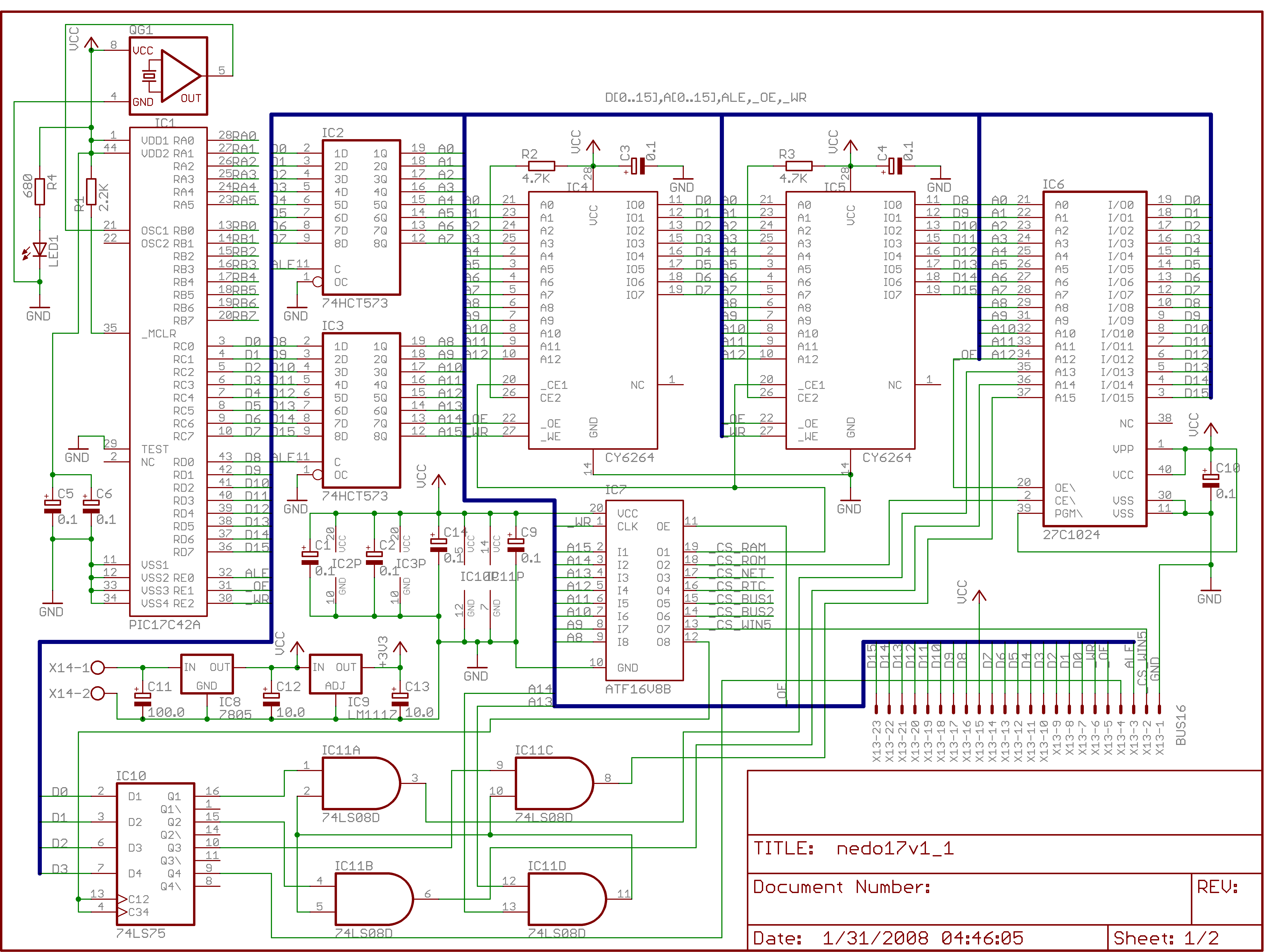
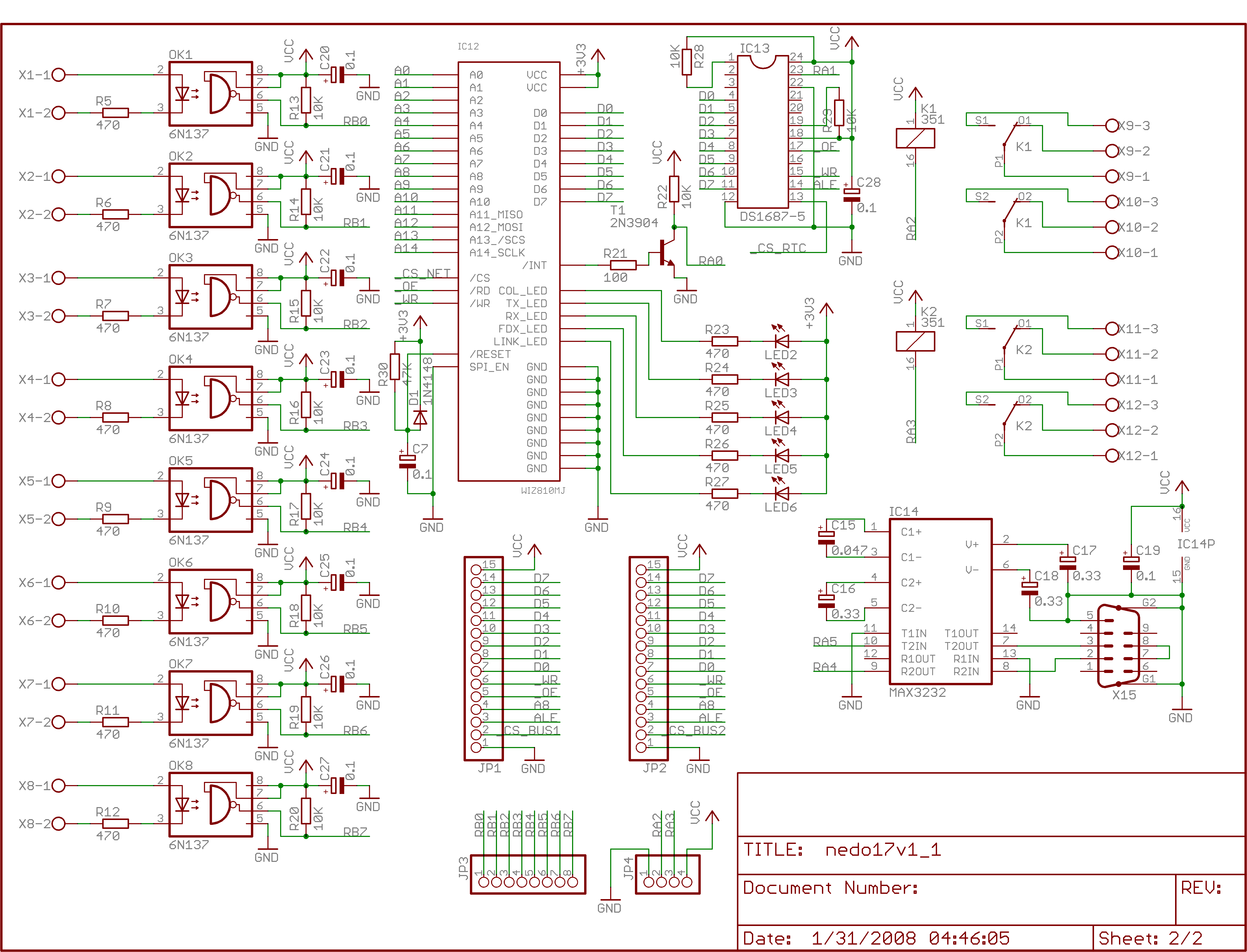
Original PIXPUTER (codenamed nedoPC-17) was designed in 2007 around PIC17C4X - we can target PIC17C43 or PIC17C44 in PLCC44 that has the same number of data registers (454), but different amount of on-board ROM that we will NOT use anyway, because MCUs connected in microprocessor mode when program is running from external memory, not from on-board ROM (that is not even accessible in this mode) - so we may choose PIC17C43-25/L (PIXPUTER runs on 20 MHz) because it's cheaper than C44. External memory could be accessed by 16-bit multiplexed bus (16 bit address and 16 bit data) with 3 control outputs (ALE, /WR and /RD). PIC17 instruction set is having special commands that could read or write words from/to external memory (so program memory may be used as data memory). We split those 65536 directly addressable memory cells into 8 baskets 8 Kwords each:
| # | Address Range | Description of Memory Region |
| 0 | 0x0000...0x1FFF | ROM (unswitchable - always bank 0) |
| 1 | 0x2000...0x3FFF | External ROM (cartridge with 2 banks - 2x8Kwords) |
| 2 | 0x4000...0x5FFF | RAM |
| 3 | 0x6000...0x7FFF | ROM (switchable - any of 8 banks, switched by ROM_CTRL register) |
| 4 | 0x8000...0x9FFF | Registers of WizNet W5100, RTC, ROM_CTRL, External buses |
| 5 | 0xA000...0xBFFF | Reserved for future |
| 6 | 0xC000...0xDFFF | TX buffers of WizNet W5100 |
| 7 | 0xE000...0xFFFF | RX buffers of WizNet W5100 |
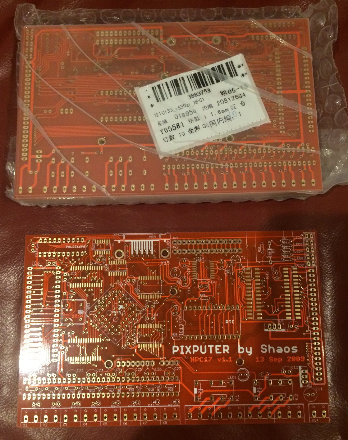
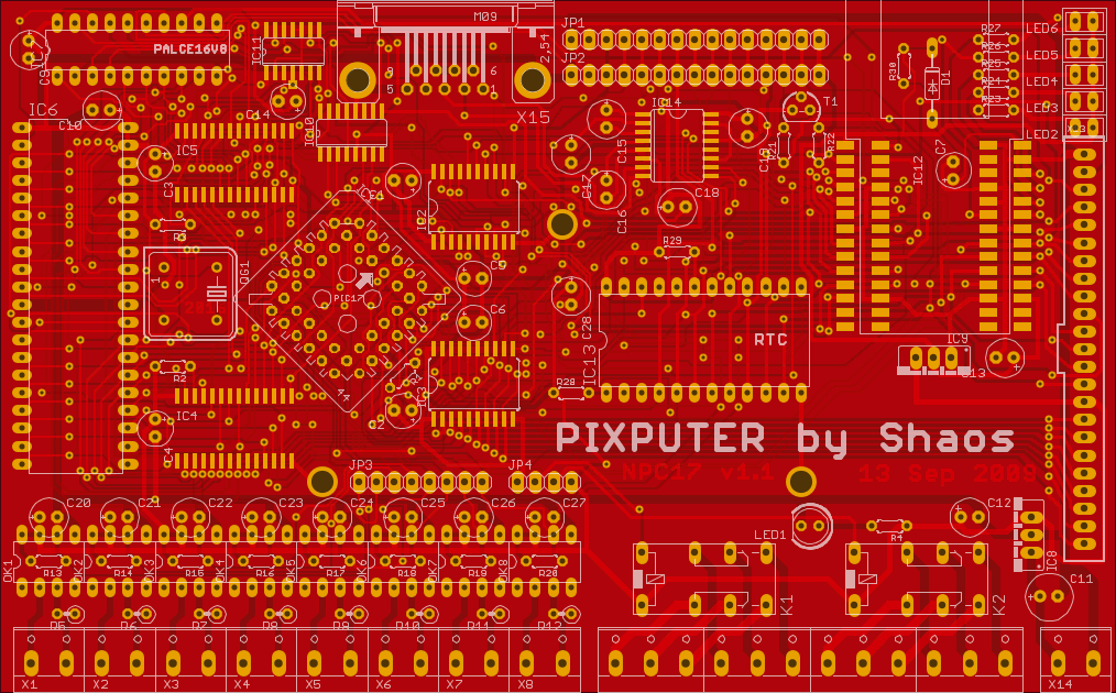
This memory map is slightly different from what was initially designed in 2007 (and described in PDF from 2009), but thanks to Programmable Logic Array 16V8, which was used as address decoder, we can remap it without changing PCB or schematics. ROM is 64 Kwords chip (ultraviolet erasable) where 1st 8Kwords (bank 0) always mapped into 1st memory range of the PIC and 0x6000...0x7FFF may have any of 8Kwords mapped into it using register ROM_CTRL (it works as write only) - 3 lower bits set index of ROM bank that has to be mapped and 4th bit may swap banks in external ROM mapped into range 0x2000...0x3FFF. RAM is two 8-bit 8KB chips permanently mapped into range 0x4000...0x5FFF. WizNet chip W5100 mapped into higher half of the memory with some small gaps used for other purposes as RTC, ROM_CTRL 4-bit register and external buses (actually higher half of this region 0x9xxx is reserved for future along with next region 0xA000...0xBFFF - 12Kwords total).
 SHAOS
SHAOS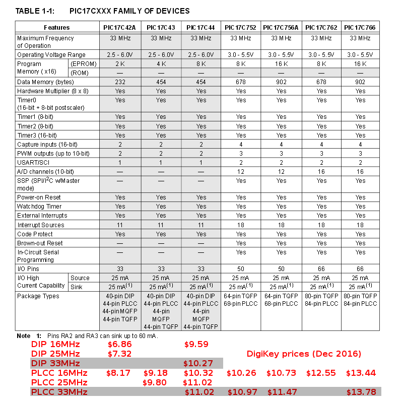



 Bentendo64
 Pascal
 Grant Giesbrecht
I like this project, because it's weird.
PIC17Cxx, oh my! And they still manufacture it, such as relict.
Are you planning to run this one with some specific software?