 adria.junyent-ferre
Below is a description of the project following the design process step by step.
High level design
I needed a clamp with a stable closed position that I could control from a microcontroller. The clamp didn't need to be too strong so I decided to keep things simple and use a clothes peg as the basis for the design. I initially thought I'd use an electromagnet from a big contactor to open the peg but I found out car lock actuators (see below) are strong enough and cheap (£3.95) and decided to use one.

The lock actuator has a "travel distance" of around 2 cm. It is meant to be fed short voltage pulses from the car battery (12V). The resistance of the coil is around 2 ohm, which means the motor will draw 6 A and produce 72 W of heat (!!!!) if fed this voltage continuously.
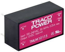
Because my application only needed the peg to open once or twice a minute, the actual average power I needed was much less than 72 W. I had a compact Tracto Power supply (TMLM10115 -see below) rated 12V at 0.83 A (£11) laying around and I thought I could combine it with a little power converter and use it in my application.
(Electro-) Mechanical design
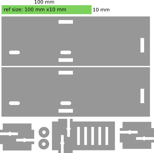
The first thing I needed to do was to figure out how much force I would need to open the peg and how long I would need the actuator to be applying force in order to open the clamp. I designed a laser-cut wooden frame to hold the actuator and the clothes peg in place. Rather than using a 3D modelling software, I drew the design in Inkscape straight-away as the geometry was simple enough.
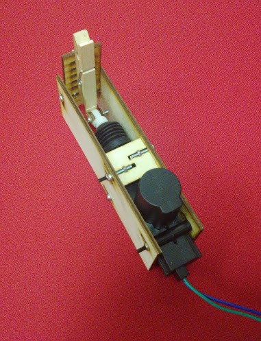
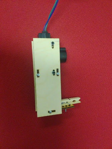
Once I got the actuator assembled, I used a signal generator and a power supply to apply voltage pulses. Unfortunately, my supply was unable to give more than 1 A, but I got a rough idea of the amount of time I needed to apply force from the actuator in order to be sure I'd open the peg (around 1 second).
The need for an energy buffer
For the design of the power converter, I thought it would be interesting to use capacitors to store the charge I needed to open the peg. A very rough estimation of the capacitance I needed was obtained by assuming I'd completely discharge the capacitors in around 1 second (therefore the time constant RxC needed to be 0.33 s). This gave a capacitance of 0.33 F. Such capacitance is hard to achieve using normal electrolytic capacitors but can be reached with ease using supercapacitors.
Supercapacitors are commonly used nowadays and can be sourced easily. Still, they have low voltage ratings and in many cases their effective series resistance is high as they are meant for low current applications (not my case!). After considering different series-parallel combinations, I found a 1 F supercapacitor rated for 2.7 V with a series resistance between 0.1 and 0.2 ohm (£1 per unit!). By combining 5 of those (£5!) I got an equivalent capacitance of 0.2 F with a rated voltage of 13.5 V and a series resistance of 1 ohm, which was ok for what I need.
A simple constant-current charging circuit
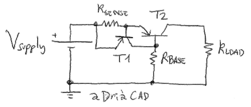
The next step was to decide how I would charge the supercapacitors. I was tempted to use a simple 15 ohm resistor between the 12V source and the supercapacitors, but I thought this would be too easy and I'd rather design something a bit more challenging. I decided to design a little non-linear resistor using BJTs. The circuit is very simple: a resistor in series with a power PNP BJT is used to sense the current, the voltage across the resistor is used to feed current to the base of a signal PNP BJT that will lower the voltage from emitter to base of the first BJT to lower the current (see below).
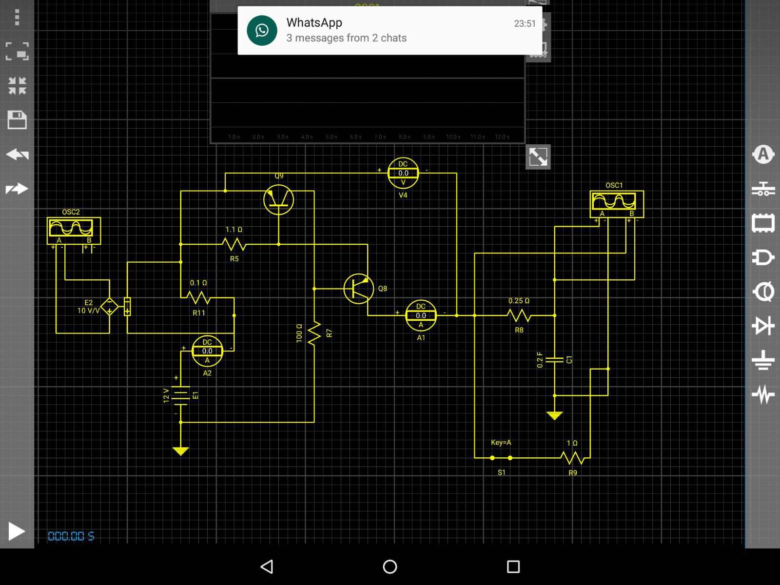
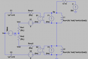
I tested the circuit in simulation using Droid Tesla simulator for Android, built the thing and surprisingly got very decent results at the first try. By the way, I like Droid Tesla because it is based on Spice and it is one of the few interactive circuit simulators for Android (if not the only) that has decent transistor models (Early effect, etc).
My greatest concern was the potential overheating of the devices. The power BJT...
Read more »

 Lithium ION
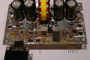
 jbb
jbb
 Jakob Wulfkind
Hi Saabman, this worked well enough for some 4 years now, I just needed the peg to be open for some 1 second so the Arduino that triggers it holds the transistor conducting that amount of time. The circuit, as is, wad never designed to be PWM-controlled (probably the layout is bad, etc). A better design would replace the current limiter by a current-controlled buck converter, which would fix the issue with f heat loss in the converter. The coil driver could be replaced by something capable of high frequency switching so that the current of the motor could be controlled properly. Once that was in place it would make a lot of sense to try your suggestion: deliver a spike of current to get the motor to move and keep a lower steady current to prevent it from closing. This isn't too hard to design and it would make a nice little project. By the way, there exist dedicated integrated circuits for driving relays that are inexpensive and deal with overcurrent protection in case of short circuit and other interesting things.