Close
0%
0%

Electric Heart

A dual analog SMPS using components that the average maker is likely to have lying around

Similar projects worth following
Switched-mode power supplies are rapidly becoming the standard for consumer electronics due to their efficiency and low heat output, but making one on the fly, to the specifications you need, can be quite difficult and usually requires specialized parts that you must order online. This project aims to change that.

Circuit theory:

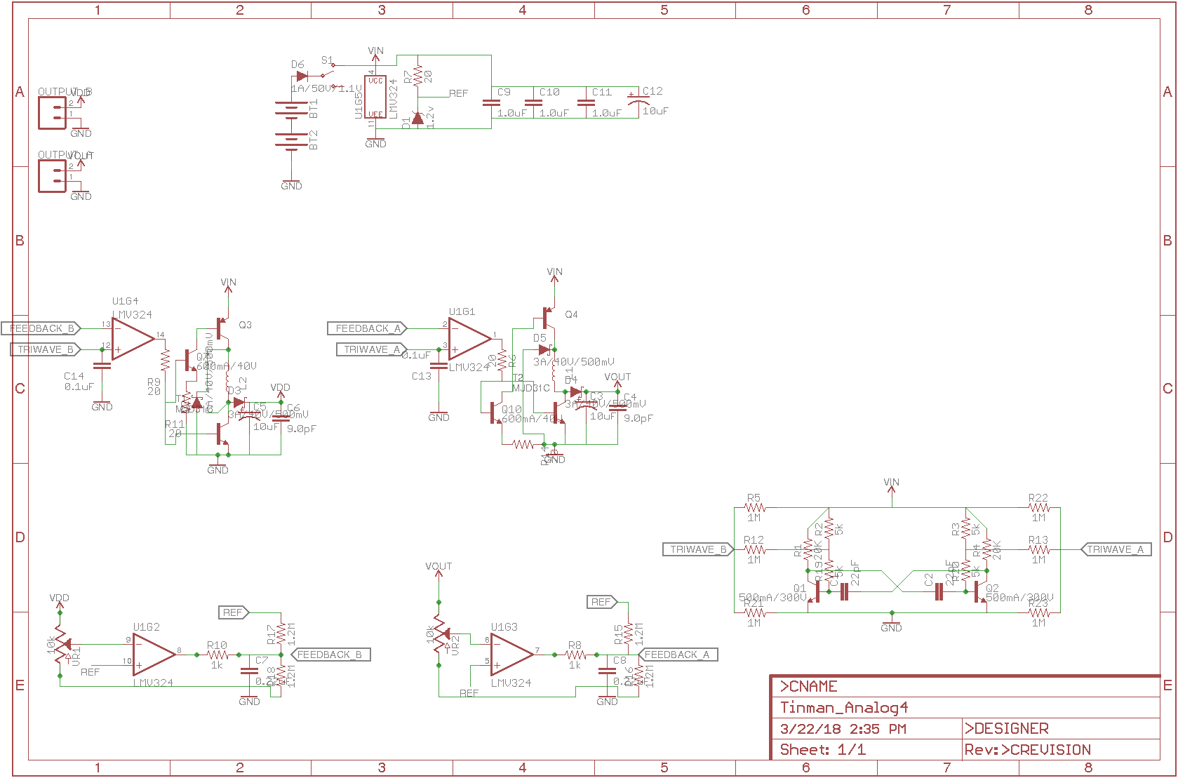
  • Inductive Switched-Mode Power Supply:
    • In broad terms, an inductive SMPS is a circuit that takes advantage of an inductor's tendency to work against changes in current -- so if you switch current on, it will briefly create a voltage going the opposite direction, and if you cut off the current, it will continue to push current forward very briefly. There are three distinct methods of exploiting this effect: the Boost, Buck, and Boost-Buck converters.
      • The Boost Converter  steps voltage up at the expense of current. In this configuration, an inductor is connected to a current source, and a switch (usually a transistor) is used to alternately allow current to flow through the inductor from input voltage to ground and then block the flow of current, forcing the energy stored in the inductor to flow through the output circuit. A blocking diode allows the higher voltage created to flow to the load, and then prevents it from flowing back into the source once the power in the inductor is exhausted. 
      • The Buck Converter  steps voltage down while increasing current, by alternately allowing current to flow from the source through the inductor to the load and then blocking the current source, with a diode allowing the energy stored in the inductor to continue to flow with the source current switched off.
  • Oscillator
    • The oscillator used in this circuit is just a BJT astable multivibrator, with the oscillation frequency set by the RC constant on each half of the multivibrator (see the instructions for the specific formula). This would normally yield two complementary symmetrical square waves, but the RC integrators between the multivibrator and the op-amp transforms this output into a sawtooth wave. In the Op-Amp, each sawtooth wave is compared to a feedback-controlled voltage (see below), which determines the exact pulse width of the output square wave fed into the transistors driving the boost or buck converter.
    • Because the two sawtooth waves are complementary (meaning that when one rises to its peak, the other falls to its trough), the two boost converters' power draw cycles will be staggered, reducing the burden on the power source (except in the case of very heavy power usage, in which case each converter's duty cycle exceeds 50%, however even then the time that both inductors are drawing power should be relatively brief.)
  • Feedback system
    • The difficulty in real-world power supply designs is that the load, or the device you are powering, usually will draw different currents (which looks like changing its resistance) at different times, and greater current draw causes the effective voltage between the source and ground to decrease. To combat this, the power supply needs a feedback system that will respond to the changing resistance and increase or decrease the power that it supplies. 

Heart v3.png

The latest version of the electric heart schematic, now with component values that actually work!

Portable Network Graphics (PNG) - 32.17 kB - 10/18/2018 at 20:32

Preview
Download

Portable Network Graphics (PNG) - 28.04 kB - 01/07/2018 at 20:28

Preview
Download

HyperText Markup Language (HTML) - 2.39 kB - 01/06/2018 at 19:36

Download

  • 1 × LM324 quad Op-Amp (or equivalent op-amps/comparators) You need four op-amps or comparators to make this work, but as long as they work on the desired input voltages and frequencies, you don't have to be too picky. I recommend using a quad-package IC just for the simplicity of having one shared set of vcc/GND pins and not worrying about differing frequency responses/slew rates/etc.
  • 2 × Inductors should be roughly the same inductance unless you feel like doing a lot of extra math. You can wind your own around a set of washers or nuts in a pinch
  • 1 × breadboard Solderless breadboard, etched PCB, actual board for slicing bread with wire-wrapped terminals, I ain't gonna judge.
  • 1 × Power source Batteries, solar panels, Stirling generator, whatever, just make sure that it's at least one volt more than the total voltage drop of your switching circuit, and has enough current to drive whatever you're trying to power. Please exercise due caution if using high-power sources like wall outlets -- should you electrocute/explode/poison/irradiate yourself, I offer the exclusive service of limiting my "pointing and laughing" session to five minutes or the duration of your eulogy, whichever is longer.
  • 2 × NPN small-signal transistors 2n2222 or similar variants, whatever you have on hand (these can be power transistors, but I'd avoid that just because of the extra space needed -- these transistors only need to carry a few milliamps). Try to use the same variety to avoid wonky behavior from the multivibrator circuit, but it should be fairly tolerant.

View all 12 components

  • Aaaand we're back

    Jakob Wulfkind10/18/2018 at 20:31 0 comments

    More life happened, more things got in the way, but I've been making slow progress. Here's the latest version of the electric heart, with component values that actually work.

    Still to come, tested versions of an automatic boost/buck/boost-buck selection system, PCB layouts, and an automated readout system.

  • No plan survives first contact with life

    Jakob Wulfkind04/07/2018 at 00:55 0 comments

    So obviously I didn't post more build logs like I was planning. Being a caretaker for a chronically ill spouse means sometimes having to give up your plans to handle some of the bizarre things that life throws at you, so I wound up stuck at home for a long time doing a great deal of hard work, and by the time I was free, I was so tired that I didn't have the energy to do anything besides play Skyrim for a couple hours and then flop face-first into bed. Happily, bashing Draugr into submission seems to have recharged me a little bit.

    So, onto the build log.

    I forgot when I was typing up the build instructions that the resistors attached to the bases of the two BJT's in the oscillator need to be at least one order of magnitude higher than the resistors attached to the bases -- so when I went to reassemble the circuit as I had designed it, it wouldn't oscillate, and I spent an hour banging my head in frustration before I realized my mistake. 

    But realize it I did, and I got the oscillator back up and running, as you can see... just in time to discover that my brand new IRF510 MOSFET is toast (don't trust Radio Shack, kids). So I'm still down one working model, but hopefully I'll have a fully functional prototype to demo in my next build log. So here I am, typing my build log at the laundromat -- hopefully I'll have more to report soon.

    Side note: I'm still going back and forth with myself on whether I want to continue to use the triangle waves from the transistor bases or rectify the square wave output into a triangle wave -- the latter would change in the same proportion as the voltage divider in the feedback input should the input voltage change, but it would require more components and more math to operate, whereas the former would be far easier to use but might do some weird things if the input voltage changes too much.


  • Whoops, forgot to post this

    Jakob Wulfkind03/22/2018 at 20:37 0 comments

    Almost forgot, here's the most recent revision of the circuit design I'm using (ignore the resistor/capacitor values, they aren't accurate right now, math corrections to come soon)

  • *tap tap tap* This thing on?

    Jakob Wulfkind03/22/2018 at 20:26 0 comments

    So as you may have guessed by this project's feed entry, I didn't just start work today on it, but since I managed to get four days off in a row from work I'm declaring the next few days to be my own personal mini-hackathon for this power supply project, which will hopefully end in me completing the documentation for this project, finishing the design equations, and being able to reliably produce this power supply in whatever number is necesary. 

    Where I am so far:

    I have already built this circuit a few times and verified that it does reliably produce a steady current at the desired voltage (highest it's gone is 67v) and is reasonably tolerant of load changes (so far I just tested it with a potentiometer and a 555 attached to a dummy load MOSFET). Because of a recent move, the assembled circuit wound up being bounced around in a briefcase for several weeks and now needs to be reassembled.

    What I hope to accomplish this weekend: 

    I desperately need a bench power supply (or five) for other projects, so I'm hoping to get one assembled, tested, and working that can output two selectable voltages with variable current control and read out said voltages/currents on an LCD panel. I also hope to finish adapting this into a fully parametric design so that others can build this power supply from scratch without needing to bash their heads against several pages of calculus like I did. 

    What the future holds:  

    I'm hoping to adapt this system into something that I can sell on Tindie, and also planning on adapting it for power-harversting purposes like MPPT controllers for solar panels and charge/speed controllers for wind turbines. 

View all 4 project logs

  • 1
    Assess and Plan

    Before you begin building this device, figure out what you're going to use it for. What voltages should it output? What current level? What will the variation be in the load you are driving? Is this going to be a general lab power supply, or are you planning on sticking it in a device and leaving it there? What are you going to power it with?

    After you've done some thinking and assessing, try to figure out the following:

    • Vin minimum____
    • Vin maximum____
    • Iin min___
    • Iin max___
    • Vout min___
    • Vout max____
    • Iout min____
    • Iout max____

    From there, first make sure that your Vin minimum * Iin minimum is at least 2.4 times your Iout maximum * Vout maximum, then think about a few other design considerations:

    • Response time: If your device is prone to sudden extreme current draws, ensure that your power supply can intervene fast enough to compensate before the smoothing capacitors are exhausted.
    • Available components: You probably don't live down the street from Digikey's warehouse, so unless you want to wait for component delivery, see if you can build your device from components on hand. Figure out what devices you have, and look up their datasheets for things like switch-on times and voltage drops.
    • Switching Frequency: Ideally your switching frequency should be at least 14.77 (2 * e^2) times faster than your response time, but you may have to change it to compensate for RF interference or ripple current concerns, component limitations, or self-inductance/resistance/capacitance of the circuit.

    With all this information in hand, it's time to move on to the next step...

  • 2
    Math

    With the information from the previous step in hand, you'll now need to calculate your oscillator frequency. In order to do so, you'll need to calculate the minimum possible frequency with the equation 

      which rearranges to 

    and the maximum possible frequency, using the equation

    To select a frequency between these, you'll also need to be familiar with the frequency calculation for your multivibrator, 

    and find values within the above frequency range that you can achieve with the components you have on hand. As a general rule, try to keep R values high and the C values low.

  • 3
    Build the multivibrator

    The multivibrator is the actual "heart" of the circuit (and the source of this project's name), because it has four "chambers" like a human heart with complementary outputs (i.e. when Q1's collector is low, its base is high and Q2 is in an opposite state). Below is a diagram of the basic design of a multivibrator:

    [will add diagram in next update]

    There are a few things to remember about this circuit when building it:

    • R2 and R3 need to be at least ten times the values of R1 and R4, respectively
    • The total frequency of the circuit is equal to
      which simplifies to if R1 = R4 and R2 = R3.
    • As a general rule, try to keep R values as high as possible (which will put C values as low as possible) in order to keep total current losses to a minimum

View all 7 instructions

Enjoy this project?

Share

Discussions

Similar Projects

Does this project spark your interest?

Become a member to follow this project and never miss any updates