Close
0%
0%

Yet Another Arduino Clock

A 7 segment display Arduino clock with RTC, alarm and brightness control.

neoNeo
Similar projects worth following
Ever since my dad showed me his prized project, a digital 7 segment display clock he reverse-engineered from a wrist watch back when he was young, I've wanted to build a clock myself. Since I've discovered Arduino recently and am trying my hand out at diy electronics recently, I've decided to try and build an Arduino clock.

Hardware:
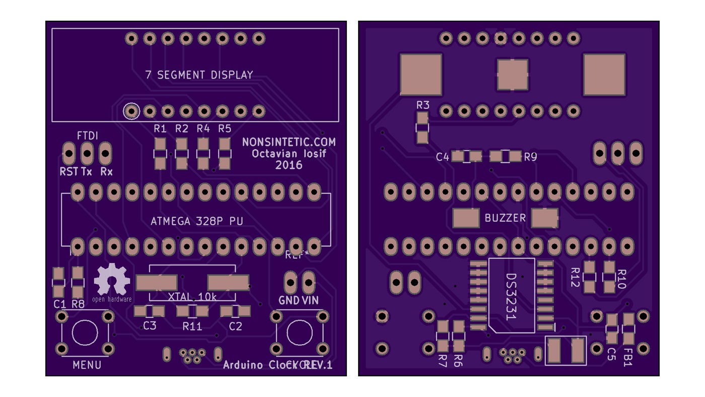
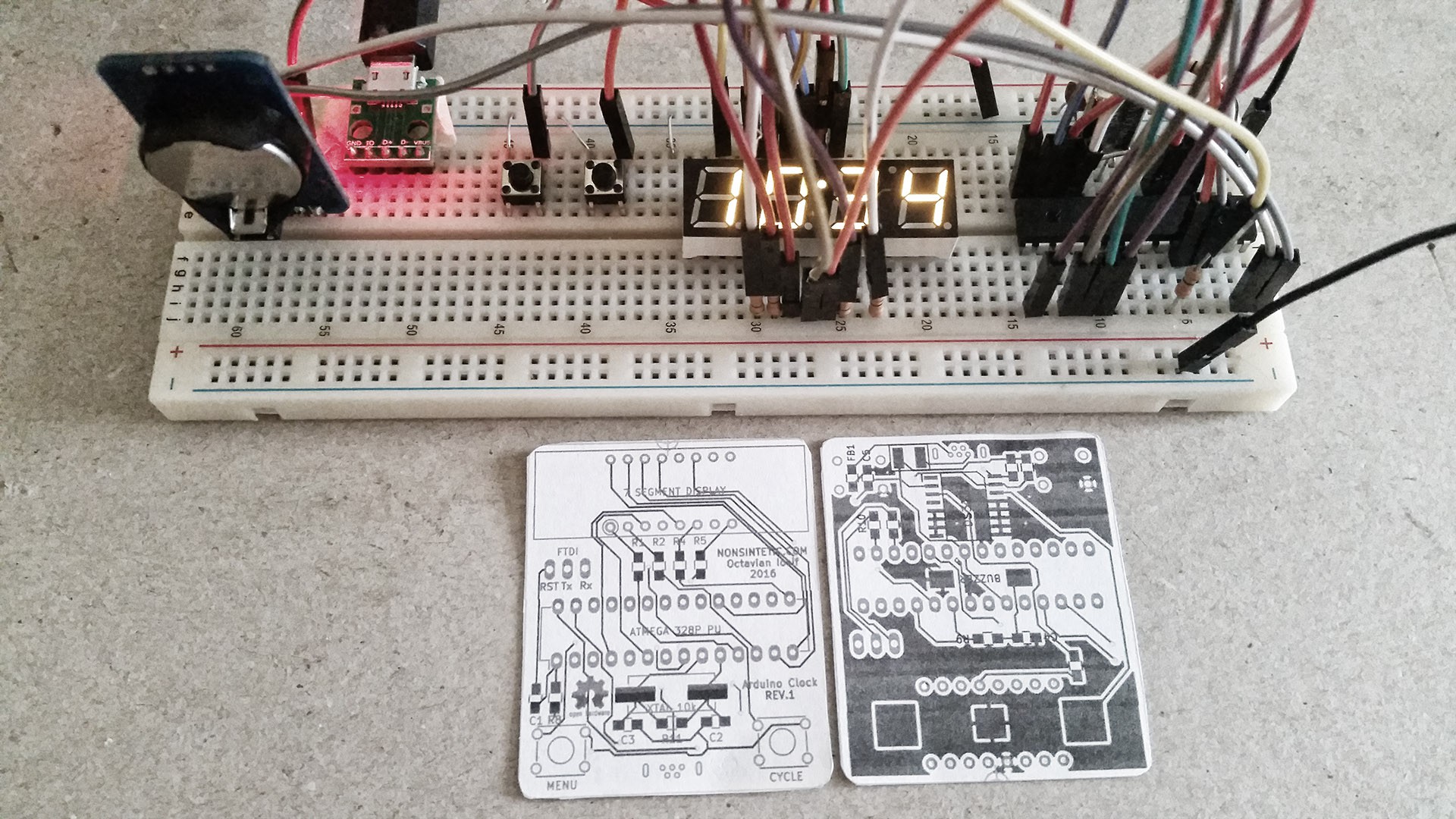
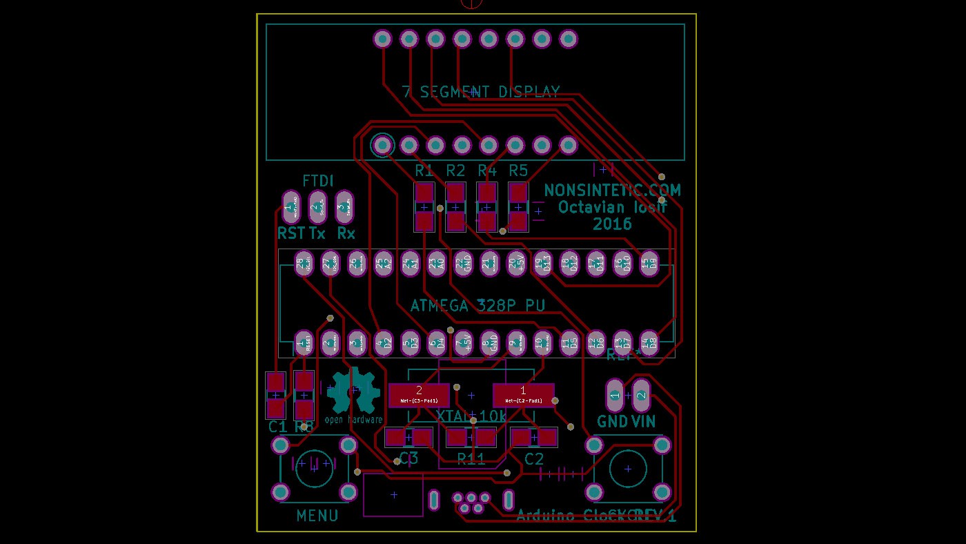
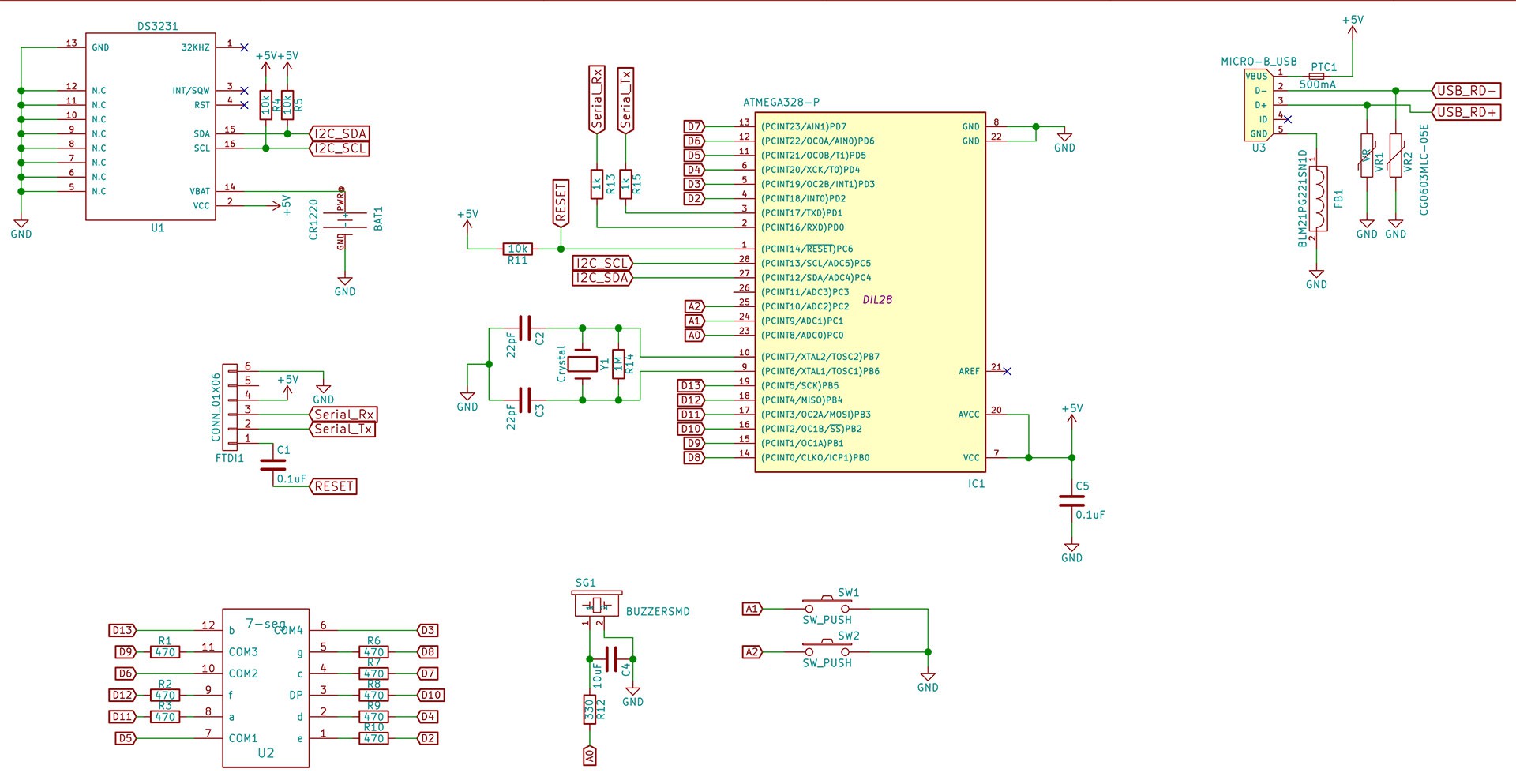
The end-goal is to make a custom PCB with a barebones Arduino setup + a multiplexed 7 segment display, basic power regulation and a RTC. For starters it's using pre-built breakouts.


Software:
The code is written in C++ using the Arduino IDE. The first iteration uses libraries from Adafruit for the RTC and 7 Segment displays, but in the end these parts will probably have to be re-written from scratch.

v2_sourcecode_arduino_clock.zip

v2 Final Source Code. Includes a modified version of the SevSeg library. Beware: this is the complex version with barebones arduino setup and multiplexed display.

force-download - 17.63 kB - 07/24/2016 at 08:48

Download

arduino_clock_v2_schematic_FINAL.pdf

v2 Final Schematic. Beware: this is the complex version with barebones arduino setup and multiplexed display.

Adobe Portable Document Format - 56.83 kB - 07/24/2016 at 08:45

Preview
Download

v2-arduino-clock.zip

v2 KiCAD schematic + PCB for the final version. Beware: this is the complex version with barebones arduino setup and multiplexed display.

force-download - 60.28 kB - 07/24/2016 at 08:39

Download

arduino-clock-v2-001.zip

v1 KiCAD schematic (simple version of the project)

Zip Archive - 12.44 kB - 07/07/2016 at 06:33

Download

arduino_clock_v2_schematic_v01.pdf

v1 - PDF schematic v.0.1 (simple version of the project)

Adobe Portable Document Format - 56.69 kB - 07/07/2016 at 06:32

Preview
Download

View all 7 files

  • 1 × Arduino Nano
  • 1 × DS1307 Real Time Clock breakout Connectors and Accessories / D-Subminiature Connector
  • 1 × 7 Segment display backpack from Adafruit
  • 1 × 330uF Capacitor
  • 1 × 2-300 ohm resistor

View all 7 components

  • Final version Source Code + Schematic + Board

    Neo07/24/2016 at 08:53 0 comments

    Since the boards have been sent off to be fabricated there won't be any updates till they get back. So I've uploaded the final source code and KiCAD project to the files section.

    There are files for two versions of the project in the files section: v1 designates the breadboard-friendly version with Adafruit display and an RTC module, v2 is the final version with bare components and a custom PCB.

    V2

    Source Code for Arduino IDE: https://cdn.hackaday.io/files/12382529751488/v2_sourcecode_arduino_clock.zip

    KiCAD Project: https://cdn.hackaday.io/files/12382529751488/v2-arduino-clock.zip

    Schematic PDF: https://cdn.hackaday.io/files/12382529751488/arduino_clock_v2_schematic_FINAL.pdf


    V1 (old simple version)

    Source Code for Arduino IDE: https://cdn.hackaday.io/files/12382529751488/clock_sevenseg_ds1307.ino

    Frizzing: https://cdn.hackaday.io/files/12382529751488/7segclock_v1.fzz

    KiCAD Schematic: https://cdn.hackaday.io/files/12382529751488/arduino-clock-v2-001.zip

  • Road to v2 - Custom PCB

    Neo07/20/2016 at 08:12 0 comments

    Having managed to get a working schematic together I decided to put it together as much as possible on the breadboard. This means switching out the I2C display with a plain old common anode display from Pimoroni, using an ATMega328P-PU chip straight on the board and powering it from a USB breakout. I couldn't find a way to test the RTC part without the breakout for it, it's way too small to use outside of a PCB, so that part will remain a mystery till the custom board arrives.

    Multiplexing the display was much simpler than I expected, although finding a full-featured library for this task was a pain in the butt, most of them only let you input a number and that's that, no colon or AM/PM indicator (hyphen as it's sometimes referred to) support on any library that I could find and most of them don't have proper brightness control. In any case I went with the SevSeg (why are there so many libraries named this?) from Dean Reading. I had to change it because I couldn't live with just inputting numbers into it, I added two functions, one for passing an array of Byte values to change all the digits at once (so I could write other stuff than just numbers) and one to set a particular digit using a byte value.

    The way multiplexing usually works in these 7 segment multiplexing libraries (including the i2c display library from Adafruit) is you store the on/off state of each segment (led) in a digit in a single byte value (8 bits = 7 segments + the colon), aka B01111111 would display an 8. The first bit is the colon on the digit, the other 7 are the a,b,c,d.. segments on the digit. 1 would be on and 0 would be off, obviously. Then the loop reads the required bit from each segment's byte value for each segment at a time and lights it or not. For example, in one iteration of the loop the script would check the on/off bit for the 'a' segment on all the digits, display it or not (simultaneous on all digits), wait a number of milliseconds (more = more brightness), then moves on to the 'b' digit etc. This way of doing it means you can put the current limiting resistors on the common anodes/cathodes of the display (the pins that control the digit, not the segments) resulting in less resistors.

    Above you can see the whole thing put together on the breadboard (it's basically just a barebones Arduino setup + a display, RTC, buzzer and buttons). Next to it there's a 1:1 print-out of the custom PCB I designed for it. As you can see it's quite small (and messy since I did it in one night). This was the first time designing a PCB for me, it was an amazing process, great fun.

    Once you set up the design rules for your project ( I got mine from the OSHpark website, since I'm going to be using their services to fabricate the PCB) it's just a matter of finding all the parts you need on Farnell or Digikey or whatever website.

    Once all the parts have been selected, you can go through each one and see if there's a footprint in your CAD program's libraries, if not you can look for one online, but usually it's really easy to make your own footprint, all serious part manufacturers give you a drawing of what the pads have to look like on the PCB, then all you have to do is reproduce the drawing they give you in your CAD footprint editor (took me around an hour to find all the parts and make footprints for the chips, buttons, battery holder and buzzer in KiCAD).

    The design I sent out is pretty crap, there's a rats nest of traces going everywhere, but I just wanted to get it out there and see if it will work, if it works I'm going to do a rev. 2 where I make it nice and elegant. Another problem I had was, since I was lazy and did a lot of the traces on the back of the board too, the ground plane on that side was messed up and full of little islands I had to go through and make sure are connected to the main ground, the way professionals usually do PCB design is they put as much as humanly possible on the front side where it's just traces and have the back for only a few...

    Read more »

  • The road to v2 - Schematic

    Neo07/07/2016 at 06:29 0 comments

    So, since the first prototype is working (it's been on my desk powered by a USB port from my PC for the last 2 months), I've taken steps towards v2 by designing the schematic in KiCAD. Given I'm no electrical engineer this has been quite fun, resulting in many many Youtube videos being watched in the process.

    In any case, the new schematic is a far cry from the breakouts linked together with wire on v1. The new version includes a plain old 7-segment display, a plain old DS3231 (it has an internal oscillator so it's not affected by temperature) and a bare-bones Arduino setup based on the ATMEGA328P-PU (I just love the big package version, it looks so old-school). For programming I've included an FTDI header to connect my programmer to, thus skipping all that mucking about with a built-in programming chip that just sits on the board drawing power for no reason 99% of the time.

    Once the parts get here, I will make a new breadboard version with through-hole passives to make sure it all works. I also have to re-write a big chunk of the code to handle the multiplexing of the display without the i2c chip led controller.

    I've added the PDF schematic and the KiCAD files so anyone interested can take a look and hopefully let me know if I've goofed up anything :)

  • Version 1 is working

    Neo06/24/2016 at 07:49 0 comments

    Since I've managed to get version 1 working with all the functions I plan to add, I've decided to add the project to Hackaday. This site has been a major inspiration for getting started with electronics so it's only natural I would submit my first project, however humble, here.

    This first version of the hardware uses just basic newbie-friendly breakouts for the complicated parts like the display and the RTC, so it should be quite easy for any beginner to get started with. This is another one of the reasons I've posted this as a project, I've been looking for an easy newbie-friendly hardware setup for an Arduino clock, but none of the projects I've found online were simple enough for me. During my search I've learned a bit more, but I hope what I've posted is enough for anyone to get started.

    Two things in this basic design I'm quite happy with: the fact that it only requires two buttons to set everything including the alarm (I only had two buttons around I had scavanged from a broken router) and the custom 'GUI' for setting the brightness (it fills up one of the segment digits progressively as you increase).

    The software part was quite a challenge since there weren't a lot of full-featured clock codes to be found online that included all the bits I needed. Because of this I've pretty much had to invent everything myself, and also because of this it's probably an inefficient mess :).

    The controls work based on a simple principle: one button switches the 'view' between clock/brightness/hour setting/minute setting/alarm hour setting/alarm minute setting, the other one changes a value in the 'view' (for the clock view it toggles alarm and is also the snooze, for brightness it cycles values.. etc.).

    For the next version of the project I plan to design a custom PCB in Eagle that will incorporate everything except the RTC (which I want to have a header for so you can switch breakouts anytime). It will probably be based on a more human solderable Atmega chip as well.

View all 4 project logs

Enjoy this project?

Share

Discussions

Similar Projects

Does this project spark your interest?

Become a member to follow this project and never miss any updates