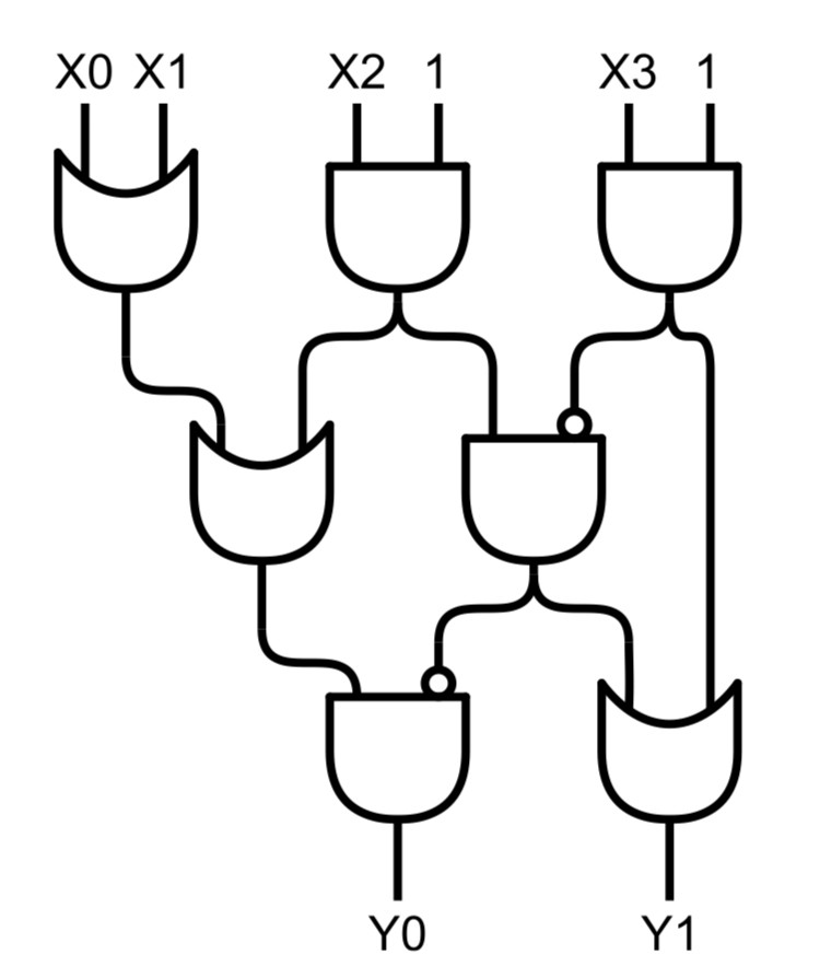
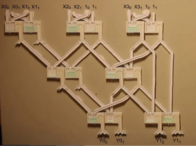
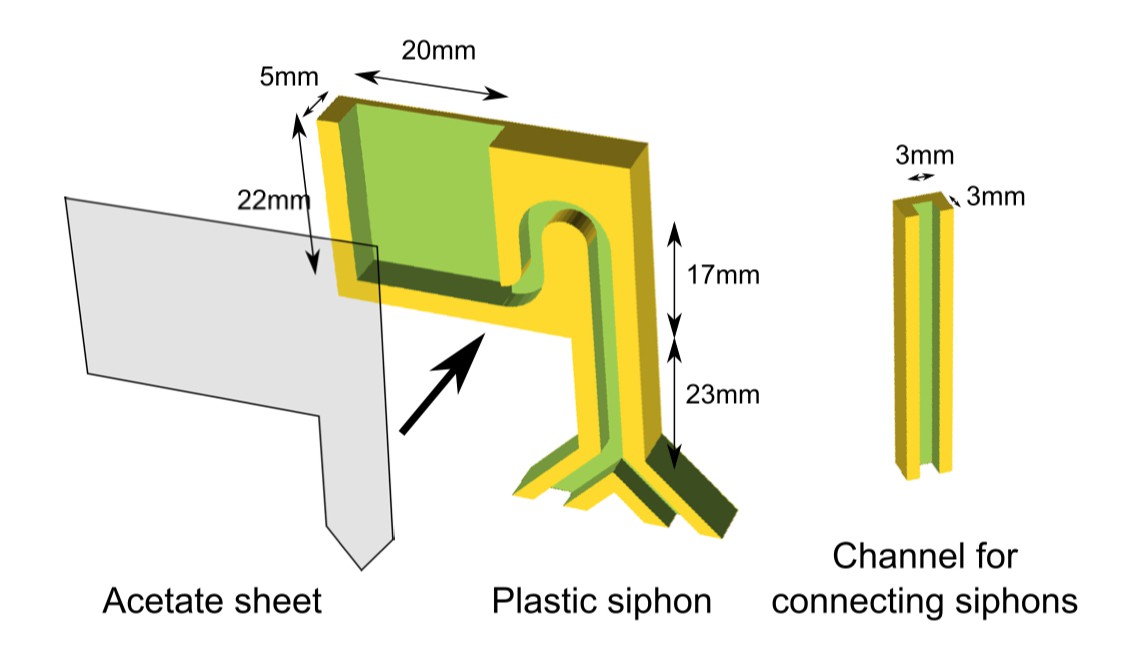
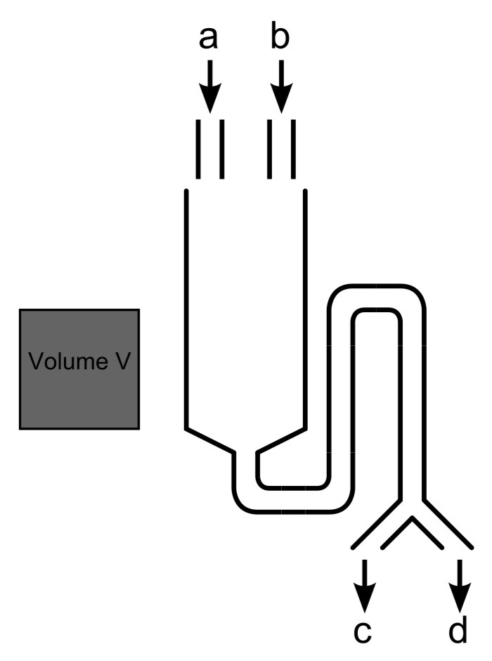
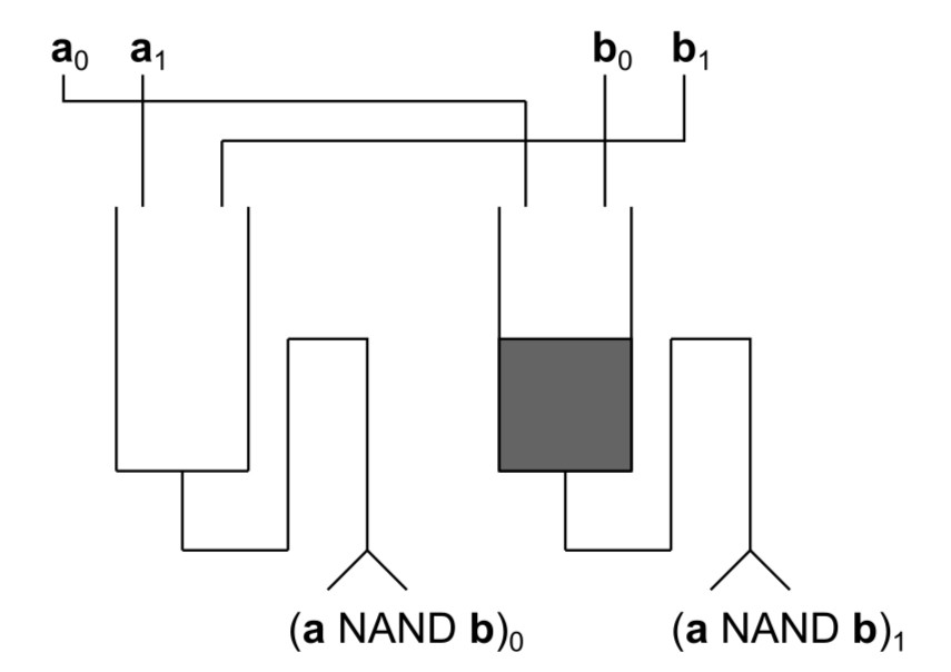
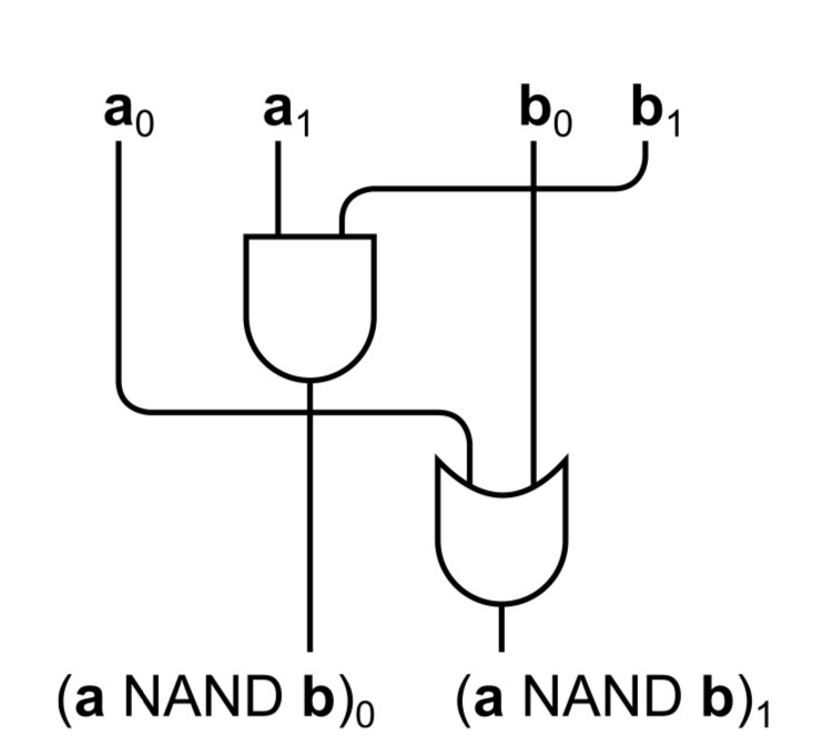
• 4-bit integer square root circuit

    will.stevens04/12/2024 at 23:51 0 comments

    The video in the first log entry shows a 4-bit integer square root circuit made from siphon logic. Here is a schematic drawing of the circuit:

    The input is the 4 bit binary number X, represented by bits X0,X1,X2,X3 (X3 is the most significant bit). The output is the 2 bit binary number Y, represented by bits Y0,Y1. The AND gates on the X2 and X3 inputs are needed because in the siphon logic implementation of this circuit these inputs feed into 2 gates each, and the AND gates effectively duplicate the inputs (see the earlier log entry explaining this).


    Here is the siphon logic implementation of this circuit, with gates positioned in the same relative locations as in the schematic:

    You will notice that because siphon logic uses a dual rail representation for Boolean values there are two inputs and outputs for each binary digit : the input subscripted with 0 represents the digit when it has a value of 0, and the input subscripted with 1 represents the digit when it has a value of 1.

  • Making siphons from bottles

    will.stevens04/11/2024 at 06:35 0 comments

    If you want to experiment with the ideas in this project but don’t have a 3D printer, then you can easily make siphons using plastic tubing and plastic bottles with the bases cut off.

    If you pierce a hole in the cap of a plastic bottle then the hole tends to want to shrink. This behaviour will make a water tight seal around a piece of tubing inserted into the hole. The tubing can be looped up against the side of the bottle and held in place with a rubber band. To make the ‘splitter’ at the output of each siphon, I purchased an off-the-shelf Y connector that fits the plastic tubing.

    You can see bottle-siphons constructed in this way in this video:

    The splitters in this video were made from plastic milk bottle tops rather than the off-the-shelf Y connectors mentioned above. Sorry about the poor quality of the video. 

  • Making siphons

    will.stevens04/11/2024 at 06:24 0 comments

    The 4 bit square root circuit shown in the video was made using 3D printed parts. I was using one of the early 3D printers (RepRap Huxley), and found that the parts weren’t reliably watertight, so I painted the insides with enamel paint to waterproof them. After the paint was dry I applied a hydrophilic coating to help prevent drops adhering to the surface, I used a car windscreen anti-fog liquid for this (Rain-X Anti Fog). I didn’t apply a hydrophilic coating to the top bend of each siphon, to prevent capillary flow through the siphon. An acetate sheet was glued to the front of each siphon, but not to the channels connecting siphons together. The image below shows the construction:

  • Future directions - a rotating computer

    will.stevens04/07/2024 at 22:04 0 comments

    It’s interesting to consider the possibility of making a siphon based computer that is operated by turning a handle which rotates a circuit through successive steps of operation. A 3D printer could be used to print the device all in one piece.

    Perhaps a 1D cellular automaton would be a good demonstration. The geometry of the circuit could be perhaps arranged so that a light shining through the circuit would project the CA pattern onto the wall once during each turn of the handle.

    One potential problem that might need to be overcome is making sure that the volumes of liquid don’t become unbalanced. The splitters at the outputs of each siphon might not split volumes perfectly in half after each operation. Any imbalance might accumulate over successive operations.

    I’m unlikely to have time to fully explore all of this, so if you are interested in doing this please go ahead, I would love to see the results. I would be happy to offer advice to anybody attempting this.

    Alternatively, the siphon logic circuit could remain in a fixed position and a cylinder surrounding it could rotate and supply the inputs at the right times, and collect the outputs and bring them back up to the top of the circuit. This is probably easier to make than a one-piece circuit where the entire circuit rotatates.

    The power source that turns the cylinder could be a person or a motor, but to remain in keeping with the rest of the project it should probably be a water wheel. Ignoring losses, if the circuit is 1 metre high with 100 inputs, each of which requires a volume of say 10ml of water, then 1Kg must be lifted through 1 metre on each revolution. Since each revolution will probably take at least 10 seconds, the power requirement is less than 1 Watt, and a 100 litre tub of water with a head of 1 metre could run the circuit for 100 revolutions over the course of 15-20 minutes.

  • Explanation part 3 : resetting a circuit

    will.stevens04/07/2024 at 21:52 0 comments

    Since dual-rail siphon gates have a fan out of 2, it’s easy to connect gates together to make larger circuits. If a larger fan out is needed then an AND gate with one input set to True can be used to achieve this.

    It turns out that these dual rail siphon logic gates have the interesting and useful property that if, after operating, they are fed the inverse of the inputs, they return back to their original state (and output the inverse of the outputs).

    To see why, it is enough to consider a single siphon and reason by induction.

    Consider first an empty siphon. During its operation in a circuit a siphon will  receive either A : zero, B : one, or C : two inputs. Only in case C will it produce an output. Only in case B will the siphon not be in the same state as it was at the beginning.

    If the siphon now receives the inverse of its inputs, it will produce an output for cases A and B, and for all cases A,B and C it will be back in the same state as it was initially.

    So during the second step the siphon returned to its original state, and because the siphon output the inverse of what it output during the first step, alil downstream siphons will also return to their original states.

    Similar reasoning applies when the siphon is initially half full.

    You can watch this happening in the video linked to in the first log entry.

  • Explanation part 2 : one shot logic

    will.stevens04/07/2024 at 07:56 0 comments

    A one-shot logic circuit is one that can only be run once, and after that cannot be used again unless it is possible to reset it. Think about a system of toppling dominoes : some people have made circuits using dominoes, but once the dominoes have fallen the circuit can’t be used again.

    A one-shot circuit is practically useless, but the idea is useful for thinking about making logic systems using physical objects because sometimes it is easier to make a one-shot system than a reusable system.

    To make a one-shot siphon-based logic system, we first of all consider the behaviour of a single empty siphon with two input pipes.

    The volume V is less than the volume needed to make the siphon overflow, but if a volume 2V is added to the siphon, it will overflow and empty, with each output c and d emitting a volume V.

    So if the siphon is initially empty, then only if both inputs a and b receive a volume V will outputs  c and d be active : an initially empty siphon behaves like a conventional AND gate.

    If the siphon starts with a volume V, then it behaves like a conventional OR gate - an input in either or both of the inputs will cause it to produce an output.

    Since we can make both an AND and an OR gate, we can build a dual-rail logic gate in which the passage of a volume V along a 1 pipe or a 0 pipe represents a single logical value. The picture below shows how two siphons can implement the dual rail NAND gate shown in the previous log entry.

    This NAND gate has a fan out of 2 (each siphon has two outputs), so we can make larger circuits by connecting gates together.

    In the next part of the explanation I will show examples of how larger circuits can be made, and explain that circuits can be reused by resetting them back to their initial state.

  • Explanation part 1 : Dual rail logic

    will.stevens04/06/2024 at 19:51 0 comments

    I’m revisiting this project because it needs more explanation. I’m going to write the explanation in a few stages, beginning with dual rail logic.

    Usually when we think about Boolean circuits and binary values, we associate a wire in the circuit with a single binary value - a high voltage represents 1 and a low voltage represents 0. AND and OR gates operate on these single-wire representations and produce an output value that is represented on single-wire output. A NOT gate turns a high voltage to a low voltage and vice versa.

    But this isn’t the only way of representing binary values using voltage levels. Another way is to use two wires, and say that a high voltage on one wire represents 1 and a high voltage on the other wire represents 0. This is called ‘dual rail logic’ or the ‘double line trick’. In this scheme there are no NOT gates - to invert a value you simply cross the wires. A dual rail NAND gate can be made from conventional AND and OR gates as shown in the diagram below.

    In this diagram the Boolean value a is represented using the wires a0 and a1 and similarly for b and for the output (a NAND b). Because inversion is just wire crossing, then by De Morgan’s law dual rail AND, OR, NAND and NOR gates are all essentially the same, and differ only in which inputs and outputs are inverted by crossing the 0 and 1 wires.

    Dual rail logic is occasionally used in electronics, but it really comes into it’s own when thinking about how to represent and implement logical operations in other physical systems, where each Boolean value can be represented by the passage of a physical object along one path or another. In this project, the object is water.

    The next part of the explanation will talk about one-shot logic, and about how siphons can be used to make the building blocks of a one-shot dual rail logic system.

  • Video explaining how the logic system works

    will.stevens08/26/2016 at 05:43 0 comments

    Here is a video of a 4-bit integer square root circuit:

    Here are links to OpenSCAD files for this circuit:

    http://www.srm.org.uk/downloads/fluidic_logic/siphon.scad

    http://www.srm.org.uk/downloads/fluidic_logic/siphontubes.scad