Close
0%
0%

Hackaday TTLers

Where DIY DIP/SSI/MSI CPU makers meet and discuss other TLA (three letters acronyms)

Public Chat
Similar projects worth following
It started simply...
I can't keep track of all the awesome "discrete" CPU designs on my own project. There is a list of such projects but it is "curated". Why not make my own list and invite like-minded hackers ?
If you have a similar project here, drop me a message and I'll add you to the contributors.
Then...
The group evolved towards the exploration of all the transistor-based technologies and the associated ideas. So we study how to make basic logic building blocks in standard and exotic ways.
The "Team" is a selective who's who of people who designed their own discrete computer or developed advanced logic circuits.
Come and chat with us on the open forum if you have ideas or questions !

For practical reasons (it's impossible to list everything on the 'net), the "project" is mostly about gathering people from HaD who built their CPU (or at the very least digital electronic devices). Here are some external links for those who just can't get enough:

Feel free to suggest or add links of the same kind :-)

PS: the project's logo comes from Wikipedia

PPS: let's not forget the two lists https://hackaday.io/list/2402-homebrew-computers and https://hackaday.io/list/25846-homebrew-cpu but note they are subject to curator delay (and taste).


Logs:
1. Dynamic RAM with single MOSFET per bit ?
2. Bizarre DTL Logic Levels - The Discrete Component PDP-8
3. The Electronics of IBM Standard Modular System Logic
4. ECL or CTL : what's the fastest topology for discrete gates ? [updated]
5. TTL inside
6. Direct Coupled Transistor Logic
7. Interactive Simulations of DEC R-Series Logic
8. Why is ECL faster ?
9. Bipolar XOR gate with only 2 transistors
10. Video Explaining DEC R-Series DTL
11. The rule of 50 (or so)
12. Bipolar transistors are ANDN gates !
13. The return of CTL
14. From XOR to MUX
15. From MUX to Latch
16. Project proposal : Ring oscillators zoo !
17. Analog Multiplexer Logic
18. Another RTL/DCTL latch
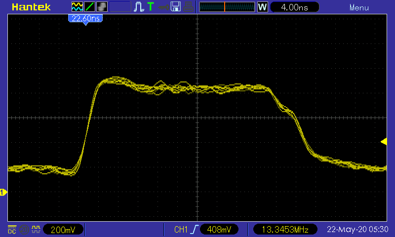
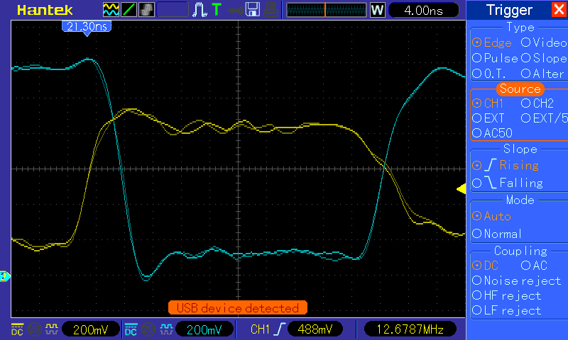
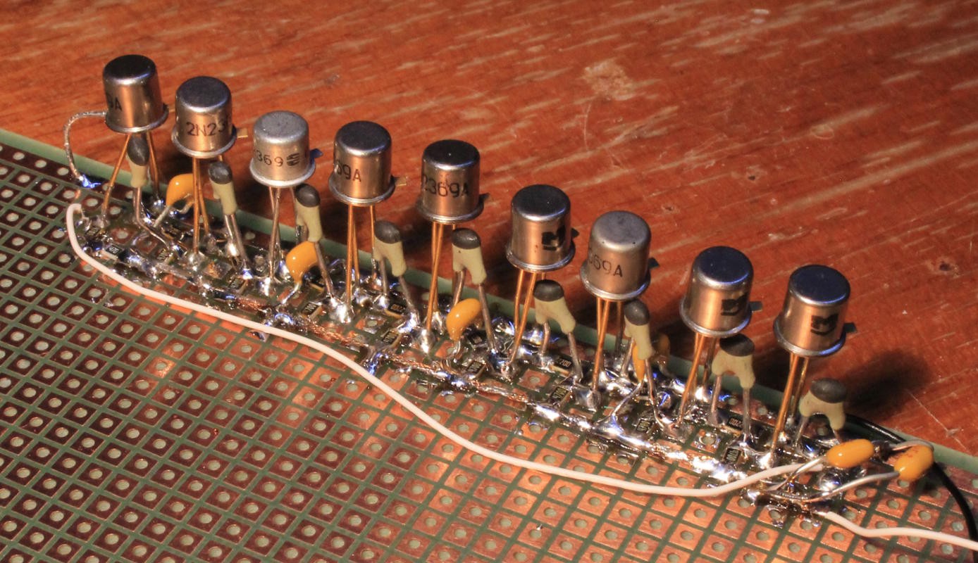
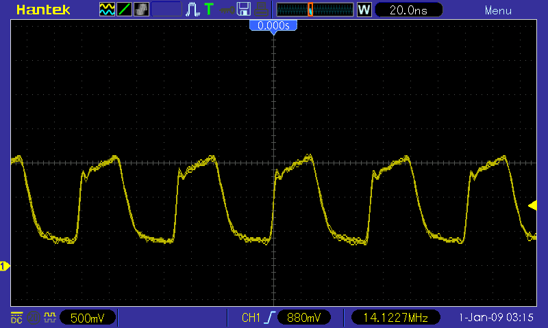
19. My own try at a RingO9 with 2N2369A
20. unexpected frequency doubler or rectifier
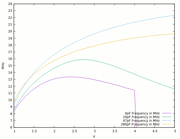
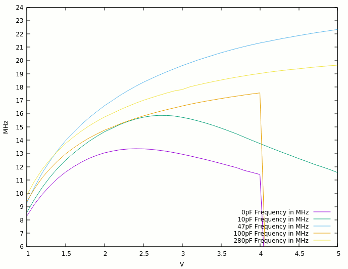
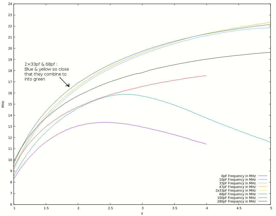
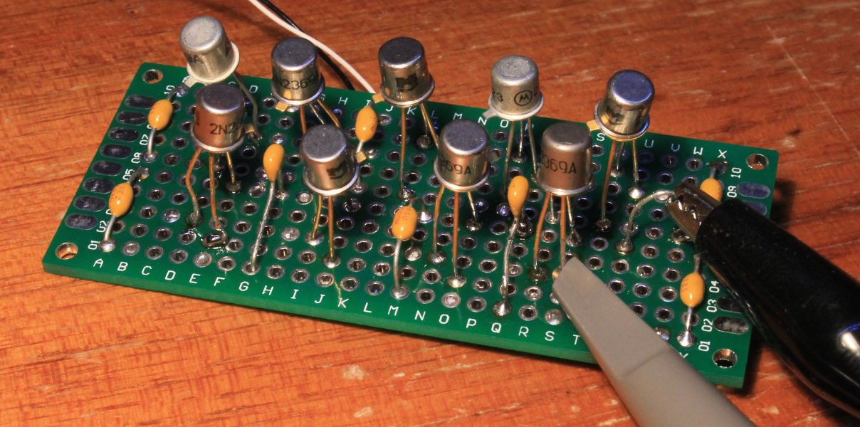
21. More 2369, with more caps !
22. RingO9 v2 : closer to CDC specs !
23. RingO9 v2 : with caps !
24. Beyond 2ns with 2N2369A
25. Dear Marcel
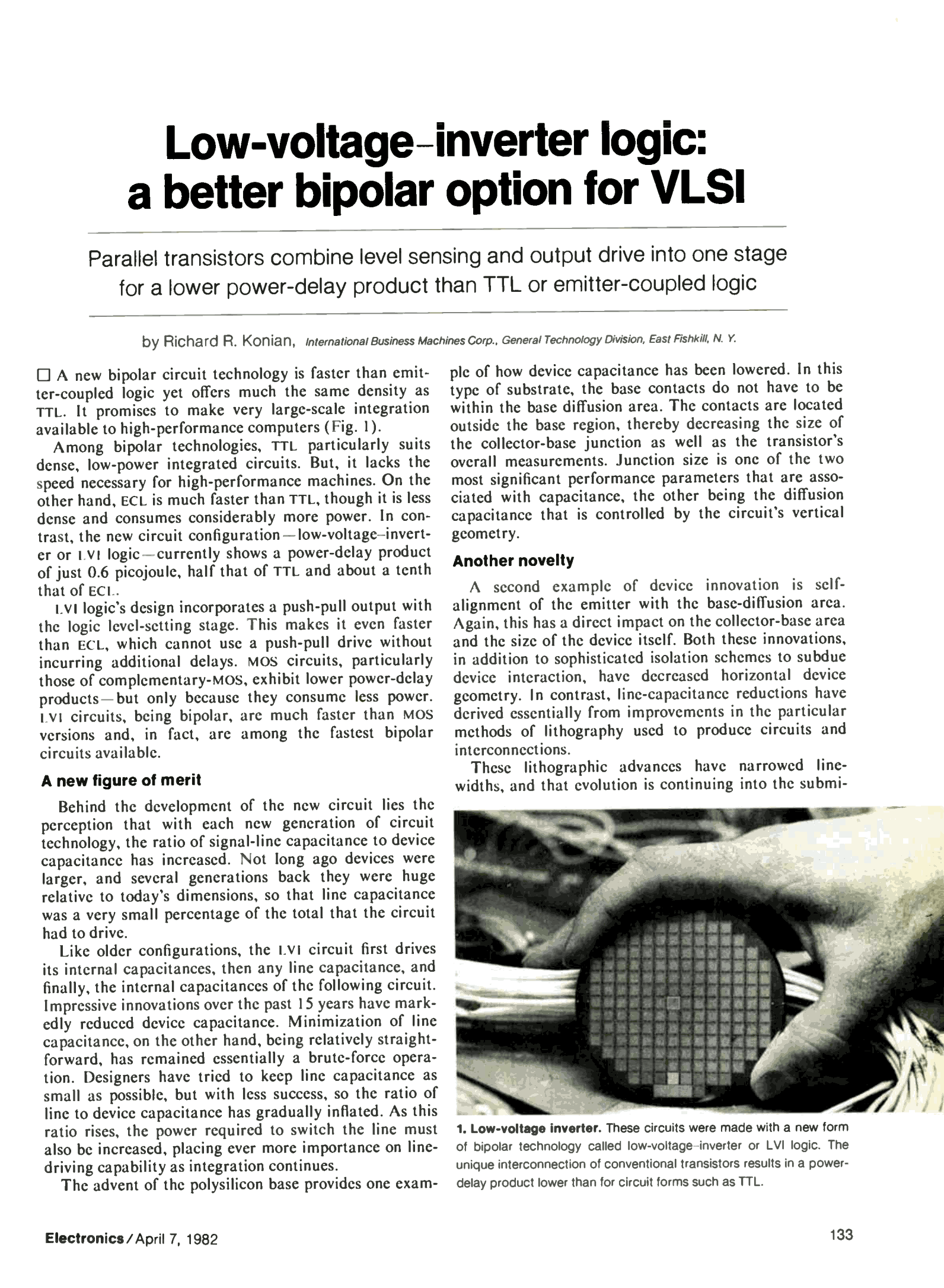
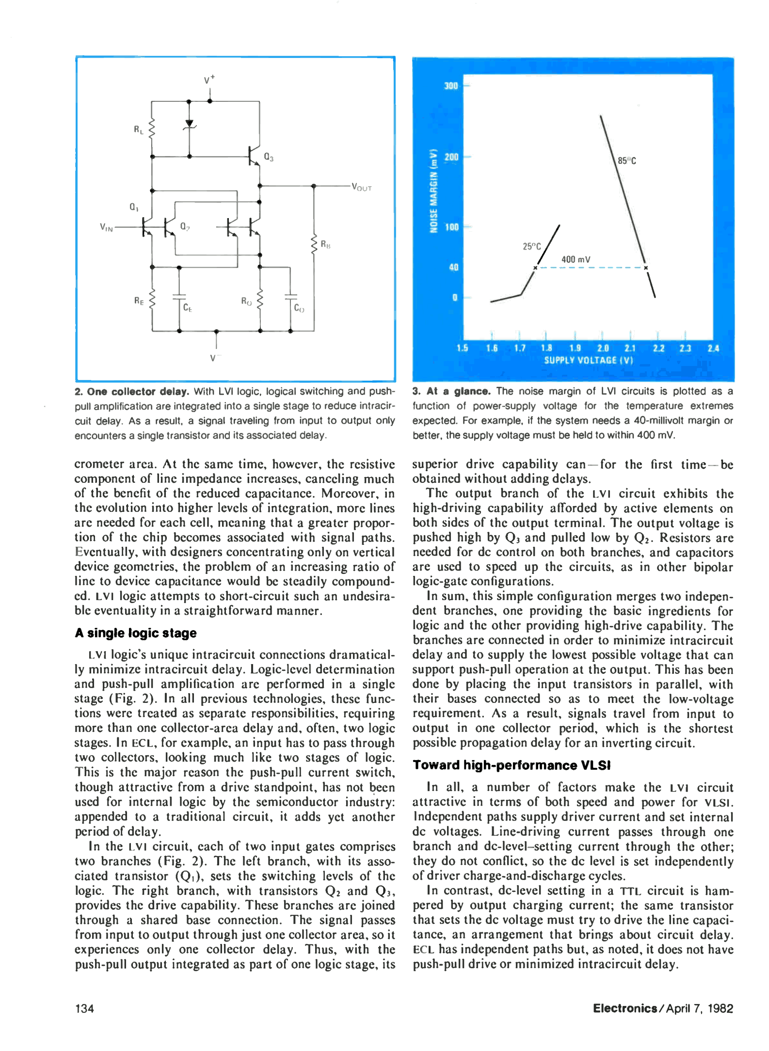
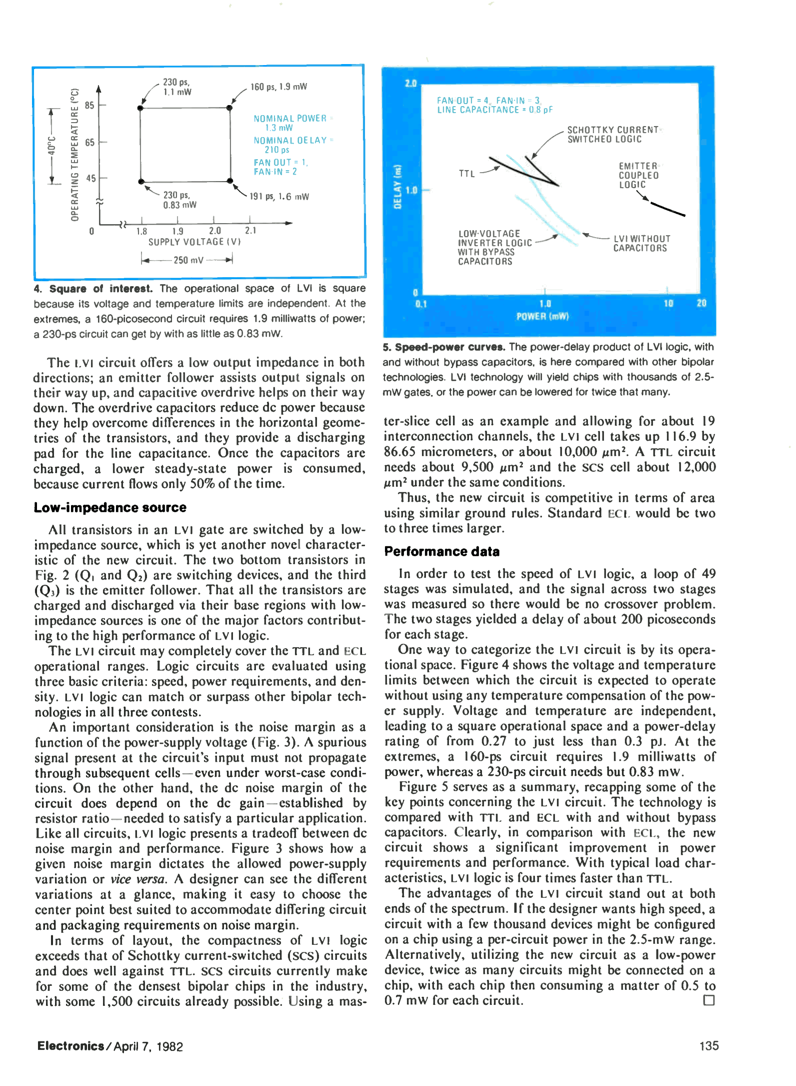
26. IBM's LVI (Low-Voltage Inversion Logic)
27. Reconstructing IBM's LVI (Low-Voltage Inversion Logic)
28. Attempting to design custom LVI inverters
.
.

DEC R-Series Logic Flip Flop.mp4

An animation of the operation of a DEC R-Series Logic Flip-Flop from a PDP-8 or early PDP-11

MPEG-4 Video - 2.04 MB - 07/04/2018 at 23:10

Download

DEC R-Series Logic Inverter.mp4

An animation of the operation of a DEC R-Series Logic Inverter from a PDP-8 or early PDP-11

MPEG-4 Video - 692.53 kB - 07/04/2018 at 23:09

Download

DEC R-Series Logic Inverter.txt

Import this circuit schematic description into this website (requires JavaScript): http://www.falstad.com/circuit/circuitjs.html

plain - 1.19 kB - 07/04/2018 at 23:09

Download

DEC R-Series Logic Flip Flop.txt

Import this circuit schematic description into this website (requires JavaScript): http://www.falstad.com/circuit/circuitjs.html

plain - 3.73 kB - 07/04/2018 at 23:09

Download

  • Attempting to design custom LVI inverters

    Yann Guidon / YGDES07/08/2023 at 23:21 2 comments

    So the last log 27. Reconstructing IBM's LVI (Low-Voltage Inversion Logic) was a lot of food for thought, and after looking back at other logs, a few ideas matured.

    1. I would like the gates to consume little power, ideally around the 1mWballpark. Most gates run in the 10mW range (and more, @Tim  got to 44mW and that's still an order of magnitude too high for my tast, sue me).
    2. I would like to use the AF240 : PNP Germanium metal-canned transistors, because that's badass.
    3. To fulfill the 1) and benefit from 2), I set the power supply to 1.5V. Though it could be lowered later but Falstad doesn't let me use a Germanium model.
    4. I drop the Baker clamps. Instead I try the "non-saturating" approach of ECL and LVI and this is where things become interesting. In fact it looks quite a lot like a HF inverting amplifier stage and in the end, that's pretty close to what we do, right ?
    5. I drop the choice of ECL because the power supply would be too high (due to several factors). Instead LVI is a bit simpler and a bit less fussy.

    LVI gates have been already studied and it's interesting because it's easier to tune for a given power draw point. The first thing to observe is that a LVI gate combines 2 sub-parts :

    1. A classic inverter
    2. A 2-transistor amplifier with emitter-follower output.

    The cool aspect is that both parts reuse more-or-less the same design for the parallel transistors (with shared base). So I can start to design the inverter first, set a given power draw, and duplicate it for the emitter follower half.

    A bit of tuning later, I get this inverter:

    So this almost acts like an inverting amplifier with a swing (in this very case of fanout=1) of 550mv-1100mV (centered around 850mV).

    The base current is limited (to about 500µA) by the 2.2K resistor of the previous stage. The other resistor is set to 470, and together they limit the overall current. There is no direct path to ground so the power can be kept in check.

    The 470 resistor is pretty critical, not just to set the working point. It also provides some degeneration, which increases the sensitivity of the base, giving the above 550mV logic swing. Furthermore the capacitor adds some more hysteresis, increases the gain temporarily, its value should not be too small (above the equivalent Miller charge, and I don't count fanouts). The overshoot on the traces above are good signs. This "boosted degeneration" is characteristic to the LVI gates and I have not seen it in other discrete deconstructions/reconstructions. Maybe this could help the DCTL gates too ?

    My concern is that the Germanium transistors have a lower Vbe and possibly a smaller swing, and I can't simulate it with Falstad's Circuitjs. I'll have to try by myself on the bench, maybe by increasing the 470 to 1K. The maximum draw I want on the 1.5V supply is 2mA, and for now I measure 750µA in active state, or 1.3mW, which amonts to 0.65mW in average.

    _______________________________________

    The next step is to duplicate the inverters, so the 470 is doubled to 1K to keep the base current low. The low Vcc is great because the resistors still have a rather low value, reducing the output impedance while also reducing the power losses through the resistors.

    The above gate has a max. draw of 1mA, or 1.5mW (0.75 at 50% duty cycle), it's quite good so far, but the 2.2K resistors must be deduplicated. Adding the emitter follower brings the new topology:

    the yellow trace at the bottom is the supply current : it peaks at 1.8mA but settles to 650µA, that's right 1mW !

    The emitter follower has a swing that exceeds 0.7V, indicating saturation, so a diode could smooth this a bit and prevent transconduction of the push-pull stage. Adding a 1N4148 increases the plateau to 750µA and the peak to >4mA so the speed benefit better be significant. But I don't see a significant difference. Another more interesting effect is obtained by setting all the resistors to 1K, as this helps discharge the base faster...

    Read more »

  • Reconstructing IBM's LVI (Low-Voltage Inversion Logic)

    Yann Guidon / YGDES07/06/2023 at 17:46 0 comments

    The last project log IBM's LVI (Low-Voltage Inversion Logic)  asked if, how and why this topology would work.

    (Above : NOR2 in LVI)

    I had no clue at first because no resistor value was hinted in the schematic. After some falstading, I think I got the idea and let's redesign it from the ground up, using the fundamentals.

    Let's go back to the old good RTL (Resistor-Transistor Logic) family with the basic inverter :

    It's sweet and simple but has many drawbacks. The DCTL family was designed to overcome some of them but the pull-up part is the nagging part that forces power/speed/fanout constraints. In the example above, the output level is crumbling under the load of RL that is lower than the pull-up resistor. So the pull resistor is often quite low, which increases dissipation a lot. And if the resistance is higher, the downstream circuits will switch slowly.

    Even with ECL, the pull resistor at the output is pretty concerning and IBM notes that ECL signals must go through 2 emitters, which also limits the speed, but ECL introduced "non-saturating logic" that increases the speed. So IBM tried to combine a pair of favourable features.

    The first thing is to remove the pull-up resistor and swith to push-pull topology. For this, 2 more transistors are required : the first is a high-side common collector (like ECL), and the second is directly tied to the input, to control the base of the emitter follower.

    There are 2 transistors doing the same thing in parallel (sharing the same base) because they drive different things that would not work if tied together. So we get to the 3-transistor push-pull:

    It's more efficient but now there are 3 semiconductors so it was not considered in the first era of computing because of the price of a single transistor. In the late 70s, the cost per junction had started crumbling to a level that made this possible (as the ECL boom has shown).

    There is no significant difference on the traces because the RL is too high, and the speed too slow to show any parasitic effect... Also due to the emitter follower, the output can only go up to Vcc-Vbe, or about 0.75V in the above example. It's higher than the 0.26V of the first example but under a low Vcc, the swing is narrow...

    But 0.6V of data swing is good enough if the circuit works at low voltage because this also reduces the power draw (as seen in the DCTL experiments of the previous years). Power is turned into heat and a lot of problems so working with low voltages is good (and this is even better with Germanium transistors hahaha).

    The next step that IBM took was to turn this gate into a non-saturating circuit. There, it gets to another level of analog wizardry but experience with ECL helped me unravel this a bit.

    The point of avoiding saturation is to keep the transistor able to switch as fast as the input signal, and saturation stores charges in the Miller equivalent capacitor of the base. The 2N2369 was designed to reduce charge storage but this did not scale in higher frequencies and other parameters. So the transistors must be kept in a sort of equilibrium, which consumes current, but not too little or too much. The absence of resistor values in the only schematic available was annoying... I also chose low-hFE transistors because it tends to decrease with the speed (and/or the current). The germanium PNP AF240 has a hFE around 20 or 30 so it should be representative.

    A particular detail of the original schematic is the diode in parallel with the resistor : this limits the output swing as well as the saturation (I suppose). That's the key to any change to the input-output level compatibility because the clamping must be changed when the Vcc is changed. For now I have chosen 1.5V but at 2Vcc, a second diode is required in series.

    I was not able to meaningfully test the interaction of the RC cells at the legs, I suppose that the diode makes the emitter resistors conduct more current and shift the base (degeneration),...

    Read more »

  • IBM's LVI (Low-Voltage Inversion Logic)

    Yann Guidon / YGDES07/06/2023 at 12:47 0 comments

    I was looking for Ken Shirriff's reference about the Intel i960 and found that on page 41 of https://worldradiohistory.com/Archive-Electronics/80s/81/Electronics-1981-02-24.pdf !

    The only other reference found on Google is on pages 133-135 of https://worldradiohistory.com/Archive-Electronics/80s/82/Electronics-1982-04-07.pdf

    That's mind-boggling. I have never heard of this or seen it before. It works with identical polarities of transistors, which simplifies the design compared to some types requiring complementary parts (NPN+PNP), lowering the cost.

    I'm sure the other TTLers will want to have a try with the types of transistors they have : either 2N2369, or AF240, or just dumb BC548... Of course one must verify that this works with discrete transistors.

    NOR2 requires 5 transistors, it's a 2N+1 count so it increases faster than ECL but even a NOR3 is worth the effort. Unlike ECL there is no complementary output though, so certain logic simplifications are not possible... So it's only NOR, like in the old-good-CDC6600. Which raises the question of how to make a suitable DFF.

    Time for some Fasltading then ? Sure.

    Who knows anything else about this ?

  • Dear Marcel

    Yann Guidon / YGDES06/08/2020 at 01:47 1 comment

    Hello @Marcel van Kervinck,

    I'm sorry you had to go away. It was a chance to chat with you and I hope Hackaday will preserve your work and logs for ever. You are sorely missed.

    https://www.eevblog.com/forum/chat/marcel-van-kervinck-(gigatron-ttl-computer)-rip/msg3083208/#msg3083208

    https://forum.gigatron.io/viewtopic.php?f=5&t=235

    I'll finish this short log by quoting him in a private discussion, when he reacted to my surprise that he wasn't a TTLer before :

    Those who use TTL are not in a hurry

    (june 16th, 2017)

  • Beyond 2ns with 2N2369A

    Yann Guidon / YGDES05/23/2020 at 03:19 16 comments

    In his log Pushing RTL to <2 ns Propagation Delay, Tim alluded that a combination of base capacitor and base-collector diode could reach 2ns of transition time per inverter.

    Well, @Tim, it wasn't that hard after all ;-) How about 1.73ns at only 5V ?

    OK it's ugly (bad baaaad probing) and the CDC levels are pretty much destroyed...

    But it's FAST and even more POWER EFFICIENT !

    I get 32MHz at 5.2V and only 77mA, or 44mW per gate, a 4.5× improvement compared to  Tim's 200 mW :-)

    What's my secret ? Not much, it's explained in the previous logs ;-)

    • ample capacitor decoupling
    • low Rb (150 Ohms)
    • finely chosen Cb (68 pF)

    But this log has a newcomer : a Schottky diode. Spoiler alert : I didn't pay much attention, I found 2 reels of SMB and SMA-packaged low voltage diodes in my drawers. I don't even remember where/how/when/why I obtained them but here they are !

    This version uses a ROHM RB751V-40 Schottky barrier diode in a tiny tiny package (almost 0603). It's limited to 20mA which matches well because the higher the current, the larger the junction, the more capacitance...

    I also have MBR0520 diodes but the higher current rating potentially increases the capacitance, which would create more problems.


    The 2N2369A is prevented from "switching hard", which has a welcome effect : less current is drawn ! At 1V the circuit sips only 3mA instead of 6mA... By 2V the difference is mostly erased, though, but at low voltages, that circuit is crazy efficient :-)

    Impressive !

    Here is the raw data for the summary graphics :

    1     6  8.292    9.653    3  12.461
    1.1   8  9.191   10.900    5  14.344
    1.2  10  9.942   11.955    7  15.976
    1.3  11  10.576  12.861    8  17.374
    1.4  13  11.140  13.663   10  18.648
    1.5  15  11.609  14.363   12  19.720
    1.6  16  12.001  14.961   14  20.700
    1.7  18  12.344  15.517   16  21.507
    1.8  19  12.636  16.029   17  22.351
    1.9  21  12.867  16.480   19  23.084
    2    23  13.053  16.916   20  23.754
    2.1  24  13.182  17.265   22  24.290
    2.2  26  13.286  17.634   24  24.875
    2.3  28  13.343  17.959   25  25.428
    2.4  30  13.364  18.268   27  25.951
    2.5  31  13.354  18.559   29  26.436
    2.6  32  13.317  18.818   31  26.875
    2.7  34  13.253  19.076   32  27.297
    2.8  36  13.170  19.307   34  27.702
    2.9  38  13.068  19.531   36  28.077
    3    40  12.952  19.749   38  28.432
    3.1  41  12.826  19.949   40  28.756
    3.2  42  12.689  20.140   41  29.063
    3.3  44  12.552  20.311   43  29.335
    3.4  46  12.408  20.472   45  29.583
    3.5  48  12.253  20.630   47  29.832
    3.6  49  12.097  20.779   48  30.050
    3.7  51  11.938  20.921   50  30.260
    3.8  53  11.729  21.060   52  30.467
    3.9  55  11.580  21.182   54  30.645
    4    56  11.426  21.296   56  30.820
    4.1   n   n      21.400   57  30.978
    4.2   n   n      21.500   59  31.126
    4.3   n   n      21.590   61  31.265
    4.4   n   n      21.681   63  31.384
    4.5   n   n      21.766   65  31.507
    4.6   n   n      21.851   66  31.619
    4.7   n   n      21.933   68  31.722
    4.8   n   n      22.010   70  31.824
    4.9   n   n      22.077   72  31.918
    5     n   n      22.144   73  31.997 

    And the gnuplot commands :

    set xlabel 'V'
    set ylabel 'MHz'
    set y2label 'mA'
    set xr [1:5]
    set yr [6:36]
    set y2r [0:90]
    set key right bottom
    set y2tics 3
    plot \
     "ringo9v2_0-68pf-RB751.dat" using 1:2 axes x1y2 title             "0pF current in  mA" w points pt 7, \
     "ringo9v2_0-68pf-RB751.dat" using 1:3           title           "0pF frequency in MHz" w lines, \
     "ringo9v2_0-68pf-RB751.dat" using 1:4           title          "66pF frequency in MHz" w lines, \
     "ringo9v2_0-68pf-RB751.dat" using 1:5 axes x1y2 title "Schottly+66pF  current  in  mA" w lines, \
     "ringo9v2_0-68pf-RB751.dat" using 1:6           title "Schottly+66pF frequency in MHz" w lines

    From there we can also plot the power/frequency curves with the following script :

    set key right bottom
    set xlabel 'V'
    set xr [1:5]
    set yr [0:2]
    set ylabel 'mW/MHz'
    plot "ringo9v2_0-68pf-RB751.dat" using 1:(($2*$1/$3))/9  title  "0pF" w lines, \
         "ringo9v2_0-68pf-RB751.dat" using 1:(($2*$1/$4))/9  title "66pF" w lines, \
         "ringo9v2_0-68pf-RB751.dat" using 1:(($5*$1/$6))/9  title "Schottly+66pF" w lines

     The result is self-explanatory :-)

    These curves were measured on this simple board :

    What else is there to say ?

    It's not the end of the adventure, of course, because it's only a ring oscillator and the diodes have destroyed the saturating...

    Read more »

  • RingO9 v2 : with caps !

    Yann Guidon / YGDES05/22/2020 at 16:01 2 comments

    a few minutes of soldering bring the base capacitors to the board... and once again Tim's curves are confirmed !

    The data :

    V     mA     MHz
    1      6    9.263
    1.1    8   10.481
    1.2    9   11.560
    1.3   11   12.456
    1.4   13   13.268
    1.5   15   13.974
    1.6   16   14.592
    1.7   18   15.166
    1.8   19   15.692
    1.9   21   16.156
    2     23   16.603
    2.1   24   16.985
    2.2   26   17.381
    2.3   28   17.731
    2.4   30   18.056
    2.5   32   18.360
    2.6   33   18.634
    2.7   35   18.899
    2.8   37   19.150
    2.9   39   19.386
    3     40   19.617
    3.1   42   19.828
    3.2   44   20.036
    3.3   46   20.223
    3.4   47   20.406
    3.5   48   20.585
    3.6   50   20.750
    3.7   52   20.906
    3.8   54   21.057
    3.9   56   21.191
    4     57   21.322
    4.1   59   21.435
    4.2   61   21.552
    4.3   63   21.666
    4.4   65   21.771
    4.5   66   21.877
    4.6   68   21.976
    4.7   70   22.073
    4.8   72   22.163
    4.9   73   22.251
    5     75   22.337
    

    The script :

    set xlabel 'V'
    set ylabel 'MHz'
    set y2label 'mA'
    set xr [1:5]
    set yr [6:24]
    set y2r [0:90]
    set ytics 1
    set y2tics 10
    set key right bottom
    plot "ringo9_2_47pF.dat" using 1:3 title "v.2 47pF Frequency in MHz" w points pt 7,  \
         "ringo9_2_47pF.dat" using 1:2 axes x1y2 title "v.2 47pF total current in mA" w points pt 7,  \
         "ringo9_2_sans.txt" using 1:3 title "v.2 sans cap Frequency in MHz" w lines, \
         "ringo9_2_sans.txt" using 1:2 axes x1y2 title "V.2 sans cap current in mA" w lines
    

     Once again the capacitor is a simple yet very effective means to go faster, yet the power curve is not affected (in a meaningful, significant way). So the efficiency is much better than v1 :-)

    At 5V the circuit easily reaches 22MHz, or 2.5ns per inverter !

    But is it necessary to go THAT fast ?  Where is the sweet spot again ? I don't think it's a good idea to run at 5V because the speed is only marginally better for a very significant increase in power draw (42mW/gate, or 1.8mW/MHz). So maybe 5V would be reserved for special cases and places that need a serious fanout.

    • 2V : 46mW => 5.1mW/gate, or 0.3mW/MHz/gate
    • 2.5V : 80mW => 8.8mW/gate, or 0.48mW/MHz/gate
    • 3V : 120mW => 13.3mW/gate, or 0.68mW/MHz/gate
    • 3.3V : 152mW => 16.8mW/gate, or 0.83mW/MHz/gate
    • 5V : 375mW total, 42mW/gate, or 1.8mW/MHz

    It would be wise to stay under the 1mW/MHz/gate, 0.5mW/MHz/gate would be even better but the fanout would be insufficient. The standard voltage 3.3V would be a good compromise but let's wait for the results with the other cap values and the diodes !

    Anyway : Going from 2.5V to 3.3V brings only 10% more speed while the power  almost doubles !


    But what is the right capacitor value ?

    the datasheet specifies < 4pF for the gate charge. So the capacitor must be higher than that to cancel the effect. So maybe 47pF ?

    OTOH I saw a speed difference that is similar between 27pF (PCB v.1) and 47pF (PCB v.2) so there would be a diminishing return, which can only be spotted by plotting the V/F curve with various capacitances.

    The smallest capacitors I have are 10pF so that's a good start. I can then add 18pF in parallel to give 28pF. Adding 47pF again will give another trace...


    The results for 10pF are below :

    From this graph, we can only suppose that the next increase would be to 220pF...

    Meanwhile, the current graph has not changed so I don't show it anymore.


    Testing with 280pF gives a pretty unexpected curve, but good to know anyway :

    After a promising start at very low frequency, the 47pF curve is already winning at 1.4V. I now have to check at 100, 68 and 33pF if there is another local maximum...


    The 100pF curve is disappointing : why is it worse than the 280pF ?

    What is so special about the 47pF I tried ? Did I fry a part ?


    Trying with 33pF caps shows interesting results as well, close to the 47pF.

    Apparently the 2×33pF combination has a very light advantage up to 3.5V : that's still good to take and much better than other values.


    Now trying 68pF gives a result very close to 2×33pf. So close that gnuplot almost mixes the colors, unless you zoom a lot.

    So 68pF wins by a tiny margin, but that's all I intended to find out :-)

    The dataset :

    1    8.292    8.563   9.116    9.263   9.623   9.653    9.391    9.863
    1.1 9.191 9.57...
    Read more »

  • RingO9 v2 : closer to CDC specs !

    Yann Guidon / YGDES05/22/2020 at 01:57 5 comments

    I'm already back with another ring oscillator ! and @Tim will love this one even more.

    The precedent one gave me some headaches due to the bad PCB design, I used a single-sided board and couldn't solder anything on the other side... ma que stupido !

    I de-soldered the transistors and made a new board with more headroom. Aaaaaand...

    13.30MHz @ 2.42V / 30mA => that's 4.2ns per inverter !

    Vcollector @ 2.5V => 13.33MHz - plateau at 1.2V

    The new parameters are not far from the previous one :

    Rb = 150 Ohms, Rc = 470 Ohms

    The change of Rb seems to have helped a bit : I now see the collector voltage saturated and not reaching Vcc (between 0.15 and 1.25V). Vb ranges from 0.18V to 0.9V => I'm now near the levels defined by CDC !

    .
    Here is the waveform at the base : the 2N2369 is driven hard at 800mV ! Discharging it however seems to take some time...

    The other change is the ample decoupling, 6×100nF + 3×10nF, I don't know if it helps but you're never too safe with that because later, I might unexpectedly scramble the local CB channels ;-)

    Yet I don't see how/why I gained 30% speed with the same transistors (I replaced one by error) and almost the same resistors (ok the base resistor has lost 25% of its value... but it's worth it right ?)

    Did I mistake a resistor somewhere ? Was one of the transistors "too slow" ? Is there a wrong resistor value in the first RingO ?

    Something else is interesting : I'm now at 30mA but the last "record" was at held at 50mA so something serious is going on here ! Efficiency has jumped too !

    The signal falls in about 5ns on the 200MHz scope, which is close to the limits. There is some overshoot, very likely caused by the ground clip and the limited BW of the whole system.

    Another good sign is that the falling edge (at the collector) is now the fast one, in 5ns :-) (we were puzzled that the rising edge was the fast one on the other board, might have been mistaken for the base ? nah...)

    The rising edge takes about 12 ns to completely reach 1.1V and this will get only longer with more loading. But in 8ns, 1V is reached.

    At 2.5V and 470 ohms shorted in DC to 0V, the collector current is drawing 5mA (approx.)

    Add to this the other current source (the base capacitance and the transistor might have 10mA transients... So once again it's in line with the CDC specs :-)

    The base current is defined by (Vc - Vb) / Rb = (1.2 - 0.85) / 150 => Ib = 2.3mA (at 2.5V, during DC ON) => in line with the expected values :-)

    The circuit alternates between 5mA and 2.5mA, this averages to 3.7mA/9.3mW per inverter (FO1).


    The delay :

    This plot is from the base and collector of the same transistor, so we see the latency of the signal : about 5ns between the middle point of the rising edge on the base and the middle point of the falling edge of the collector. It takes about 8ns from the start of the base's rising edge to the end of the collector's falling edge...

    The reverse however takes more time, due to RC loading.


    The V/F curve :

    V     mA   MHz
    1      6   8.292
    1.1    8   9.191
    1.2   10   9.942
    1.3   11  10.576
    1.4   13  11.140
    1.5   15  11.609
    1.6   16  12.001
    1.7   18  12.344
    1.8   19  12.636
    1.9   21  12.867
    2     23  13.053
    2.1   24  13.182
    2.2   26  13.286
    2.3   28  13.343
    2.4   30  13.364
    2.5   31  13.354
    2.6   32  13.317
    2.7   34  13.253
    2.8   36  13.170 
    2.9   38  13.068
    3     40  12.952
    3.1   41  12.826
    3.2   42  12.689
    3.3   44  12.552
    3.4   46  12.408
    3.5   48  12.253
    3.6   49  12.097
    3.7   51  11.938
    3.8   53  11.729
    3.9   55  11.580
    4     56  11.426
    

    Clearly : something important has happened :

    set xlabel 'V'
    set ylabel 'MHz'
    set y2label 'mA'
    set xr [1:4]
    set yr [6:18]
    set y2r [0:120]
    set ytics 1
    set y2tics 10
    set key right bottom 
    plot "27pf.dat" using 1:3 title "v.1 27pF Frequency in MHz" w points pt 7,  \
         "27pf.dat" using 1:2 axes x1y2 title "v.1 27pF total current in mA" w points pt 7,  \
         "ringo9_2_sans.txt" using 1:3 title "v.2 sans cap Frequency in MHz" w lines, \
     "ringo9_2_sans.txt" using 1:2 axes x1y2 title "V.2...
    Read more »

  • More 2369, with more caps !

    Yann Guidon / YGDES05/21/2020 at 16:55 0 comments

    Back to the workshop for the revenge of the return of the son of the Vintage Ring Oscillator !

    This time with a new ally : the ceramic capacitor !

    TL;DR : it's 60% faster !

    But the V/F curve might look different from @Tim 's experiments...

    As usual, give me some time to dump and analyse all the yummy data, come back often on this page ;-)

    Back to the circuit : it starts with the exact same board as last time.

    Ring oscillator  with 9 levels of low-grade 2369 (according to their hFE).

    Rb = 220, Rc = 470, like before.

    1nF to decouple a pair of transistors.

    But this time I add more capacitors : 100nF on the power input and 27pF to short each base resistor ! As usual, it's a step by step modification to help with understanding the effect of every change.

    From the beginning, starting at about 10MHz, I saw the incremental increase of frequency : about 500KHz for each capacitor I added. I tested very often because I didn't want to spend any time spotting soldering error.

    After a while I had the 9 capacitors wired and *bim* 16MHz without effort !

    Some tuning later, a lot of blowing, and the best frequency I got was 16.8MHz !

    That's at least 50% better than without the capacitors.


    16.81MHz at 2.45V !

    (yes I know the date is wrong)


    15M81Hz @ 2V : near the sweet spot...


    14MHz@1.5V only :-) still nice looking...


    Here is the V/F curve data:

     V     mA      MHz
    1      10      9.15
    1.1    14     10.22
    1.2    16     11.90
    1.3    20     12.78
    1.4    23     13.52
    1.5    25     14.12
    1.6    28     14.63
    1.7    31     15.02
    1.8    34     15.35
    1.9    36     15.62
    2      40     15.85
    2.1    41     16.13
    2.2    45     16.35
    2.3    48     16.53
    2.4    50     16.62
    2.5    54     16.65
    2.6    56     16.51
    2.7    59     16.41
    2.8    63     16.32
    2.9    65     16.24
    3      69     16.15
    3.1    72     16.09
    3.2    74     16.05
    3.3    78     16.02
    3.4    81     16.00
    3.5    83     15.98
    3.6    87     15.96
    3.7    89     15.94
    3.8    93     15.93
    3.9    96     15.93
    4      99     15.93

    I made more points because I want to plot a better curve than the previous one.

    More precision is hard because it's temperature sensitive and the can is connected to the collector so it must radiate quite a lot of HF...

    The 16MHz region spans from 2.06V to 3.3V and then the curve is mostly flat.

    The peak frequency moved to 2.45V : still not far from 2V.


    16.8MHz amounts to 3.3ns per inverter, down from 5.5ns with just a capacitor.

    Beware however !

    • 27pF is just a random value in the drawer : more tests are needed to estimate and choose the best value. So it's still not optimal.
    • This is very sensitive to the load ! the frequency drops quickly when it is loaded.
    • Temperature affects the speed by a few %.
    • No clamp diode yet... later :-)

    The power/frequency curve is clearly  changed as well and this is where it's the most interesting :-D

     V    mA    MHz      mW     mW/MHz   delta
    1     10    9.15     10      1.092
    1.1   14   10.22     15.4    1.507   0.415
    1.2   16   11.90     19.2    1.613   0.106
    1.3   20   12.78     26      2.034   0.421
    1.4   23   13.52     32.2    2.381   0.347
    1.5   25   14.12     37.5    2.655   0.274
    1.6   28   14.63     44.8    3.062   0.407
    1.7   31   15.02     52.7    3.508   0.446
    1.8   34   15.35     61.2    3.986   0.478
    1.9   36   15.62     68.4    4.379   0.393
    2     40   15.85     80      5.047   0.668
    2.1   41   16.13     86.1    5.337   0.29
    2.2   45   16.35     99      6.055   0.718
    2.3   48   16.53    110.4    6.678   0.623
    2.4   50   16.62    120      7.220   0.542
    2.5   54   16.65    135      8.108   0.888
    2.6   56   16.51    145.6    8.818   0.71
    2.7   59   16.41    159.3    9.707   0.889
    2.8   63   16.32    176.4   10.808   1.101
    2.9   65   16.24    188.5   11.607   0.799
    3     69   16.15    207     12.817   1.21
    3.1   72   16.09    223.2   13.871   1.054
    3.2   74   16.05    236.8   14.753   0.882
    3.3   78   16.02    257.4   16.067   1.314
    3.4   81   16.00    275.4   17.212   1.145
    3.5   83   15.98    290.5   18.178   0.966
    3.6   87   15.96    313.2   19.624   1.446
    3.7   89   15.94    329.3   20.658   1.034
    3.8   93   15.93    353.4   22.184   1.526
    3.9   96   15.93    374.4   23.502   1.318
    4     99   15.93    396     24.858   1.356
    

    The power estimate is not very precise because the integrated ampere-meter has only so many digits... The delta column has some "noise" in it but this is useful anyway !


    Gnuplotting gives nice results, sure !

    Frequency vs voltage, Current vs voltage curve :

    set xlabel 'V'
    set ylabel 'MHz'
    set y2label 'mA'
    set xr [1:4]
    set yr [6:18]
    set y2r [0:120]
    ...
    Read more »

  • unexpected frequency doubler or rectifier

    Yann Guidon / YGDES05/20/2020 at 03:10 3 comments

    So I was Falstad'ing some ECL/differential amplifier topologies and playing with the resistor values ratios...

    I found some strange behaviours with this single-ended circuit when the collector and emitter resistors are equal.

    At 5V the turning point is at 3.1V, so I created a sine wave centered around 3V with +/- 1V peaks. The output looks like a rectified version...

    The effect disappears when the ratio of the resistors is modified. This might be a desired effect or an unwanted behaviour, and since I'm playing with ECL topologies, I want to avoid this so I need to understand what is going on.

    This is important because I would like to save a transistor at the common emitter node so the resistor value must be well chosen. It's good to know that a 1/1 ratio is BAD, and changing it affects the kink point...

    But OTOH it opens up potential for fun, such as sound effects :-P

  • My own try at a RingO9 with 2N2369A

    Yann Guidon / YGDES05/16/2020 at 12:15 17 comments

    Edit: See also More 2369, with more caps !


    With a sporadic and limited access to the workshop (at last !) I can finally try new ideas ! I have meanwhile received 9K PMBT2369 in SMD but I decided to use the old stock of 50pc 2N2369A in metal can, that was waiting in a small bag that I received from various sources... What can be closer to the CDC era ? (A motor-generator ? :-P)

    This is a "mixed bag" with at least 2 sources or makers, some with golden legs, and I decided to test them. Just because I now have a better tester and it's good to see if/how the different types differ...

    Most "golden" parts fall in the lower bins and the tinned ones have overall the best gain. I made 3 bins :

    • < 60 (lowest is 46)
    • < 84
    • higher (a few up to 114 and one at 119)

    and then I use the lower gain ones to build the RingO, with 9 parts to give a low-enough frequency that makes 'scoping reasonable.

    I could have made a > 100 bin but

    • I just wanted to have a look at the spec spread
    • I wanted to weed out the lemons (and use them first to establish a baseline)
    • the temperature sensitivity makes it moot.

    After Tim's experiments, I chose from my parts bins :

    • Rc = 470 (so I can test from 2V to 5Vcc) in 0805
    • Rb = 220 (that's what I have in stock right now, close enough)

    Afterthought : I should have tried 100 Ohms for Rb. Or even 47/50 ohms maybe....

    After-afterthought : or 330 ohms (see near the end)


    And the soldering iron was turned on !

    • For the sake of simplicity I omitted the caps. They used too much room. Next time I'll look at the SMD stock.
    • I added 1nF to decouple every pair of transistor (that's 5nF but spread to ease HF transients)
    • I found some partial reels of SMD Schottky diodes but once again, decided to not use them yet.

    So I wanted to establish a baseline for speed and more importantly : explore the power vs speed envelope because... Tim found that a LOT of power was wasted. I would like to get a gate that is still "pretty fast" and yet consumes at least 10 times less power.

    For the measurements I used a 200MHz digital scope with 10x probe. The output waveform is pretty nice and quite square-y :-) No funky feature is noticed, it's plain old RTL and I didn't bother to measure the rise/fall time because the measurement circuit is not optimised.

    Still it's very telling.

    2V:

    2.5V:

    3V:

    3.5V:

    4V:

    4.5V:

    5V:

    Rise time is about 5ns. Which is odd since I expected that RC would dominate it.

    In fact something else is happening : it seems that the transistor has a harder work to totally saturate and keep Vce sat to a sufficiently low value. This in turn reduces the frequency because the transistor turns off later.

    At 5V the circuit doesn't seem to get hot, maybe thanks to the help of the metal cans and the resistors directly soldered to thick metal that can spread the heat.

    You can find a curve that is similar to what Tim found already :

    Vcc  Total   Freq.
    5V   123mA   6.98MHz  <= never mind.
    4.5V 109     7.37
    4V    97     7.77
    3.5V  81     8.61
    3V    69     9.42 <= why waste so much power ?
    2.5V  55    10.16
    2.25  47    10.48
    2V    40    10.55 <= sweet spot !
    1.75  33    10.48
    1.5V  26    10.06
    1.25  18     9.13
    1V    11     7.34  <= wow, that's still good :-D
    

    The frequency is measured by the scope but not finely calibrated. My HP freqmeter wouldn't accept the raw signal, something to do with ringing and probe impedance, I'll check that later. Still you can find the important features.

    With my choice of parts, I find that the sweet spot is in the 1.75V-2.25V range, as roughly expected, so I'm pretty happy ! But there is more to that curve.


    Let's now compute and deduce some numbers :

    Vcc  mA Total Freq. mW Total mW/MHz
    5     123     6.89    615      89
    4.5   109     7.37    490      66.5
    4      97     7.77    388      50     5V/4V=> *1.8
    3.5    81     8.61    283      32     
    3      69     9.42    207      22     4V/3V=> *2.3
    2.5    55    10.16    137      13.5 
    2.25   47    10.48    106      10.1
    2      40    10.55     80       7.6   3V/2V=> *2.9
    1.75   33    10.48     57       5.43
    1.5    26    10.06     39       3.88
    1.25   18     9.13     23       2.52
    1      11     7.34     11       1.5   2V/1V=> *5

    The power/speed ratio decreases faster...

    Read more »

View all 28 project logs

Enjoy this project?

Share

Discussions

Kuba Sunderland-Ober wrote 01/25/2024 at 22:28 point

I find logic families hard to use without a set of concise reference cards. Thus https://hackaday.io/project/191205-4000-series-logic-reference-cards - a set of 4x6" 4000-series CMOS logic reference cards. It covers everything you can buy from Texas Instruments today - and that's a lot of 14- and 16-pin parts still made in DIP, IIRC well over 100. I've checked that you can indeed still buy them by, well, actually buying a dozen of everything they sell in DIP. At least a year ago TI still sold every part with a black part# on the ref sheets. Grey part#s are not made anymore.

24-pin parts are only SMD, they dropped the big DIPs. They still make some of the 24-pin parts in high-rel or milspec CERDIP (expensive). I've also included selected legacy parts that aren't sold new anymore, but are still available in plentiful supply on the secondary market.

I have a bit of a vested interest in keeping this family alive, since I use it in projects, and would hate for it to disappear due to lack of demand. TI themselves does a rather poor job of keeping the 4000 family in relevant parametric search results. A few of the parts are only visible by searching for the specific part number and don't appear in tabulated results. 

Getting a similar reference sheet for 74-family parts will be a bigger endeavor, since there's way more of them, across several logic families, etc.

  Are you sure? yes | no

Yann Guidon / YGDES wrote 11/08/2023 at 18:29 point

http://jmprecision.co.uk/shopping/start.php?browse=1&cat=20&=SID sells kits, including a roughly 2k-transistor processor :-)

  Are you sure? yes | no

Michael Möller wrote 01/31/2024 at 11:57 point

NICE ... at a mere £532 Oh, Out Of Stock. (I looked at several products .. all out of stcok, so maybe an old site)

  Are you sure? yes | no

Yann Guidon / YGDES wrote 11/06/2023 at 22:12 point

1959 : the MIT's FX1 !
https://dl.acm.org/doi/pdf/10.1145/1460833.1460845
schematics & pictures, it used a custom manufactured L5447, a germanium pnp Microalloy Drift transistor, commercial equivalent is 2N769.

  Are you sure? yes | no

Tim wrote 11/08/2023 at 19:29 point

crazy stuff - when a wound inductor was still chaper than a bipolar transistor.

  Are you sure? yes | no

Yann Guidon / YGDES wrote 11/08/2023 at 19:45 point

it was bleeding edge technology, they were pioneers :-)

  Are you sure? yes | no

Tim wrote 11/08/2023 at 19:55 point

The CDC6600 was only a few years away.

  Are you sure? yes | no

Yann Guidon / YGDES wrote 10/11/2023 at 19:37 point

https://www.angelfire.com/oh3/ebjoew/Drum_Memory_Story.html

a multibit comparison with mostly diodes and one transistor ?

  Are you sure? yes | no

Yann Guidon / YGDES wrote 07/08/2023 at 20:42 point

Has anybody built logic gates using cascode topology ?

  Are you sure? yes | no

Tim wrote 11/08/2023 at 19:56 point

What for? To improve output impedance?

  Are you sure? yes | no

Yann Guidon / YGDES wrote 07/06/2023 at 03:08 point

Look at page 41 of https://worldradiohistory.com/Archive-Electronics/80s/81/Electronics-1981-02-24.pdf !!! what's that bipolar topology from IBM ???

  Are you sure? yes | no

Yann Guidon / YGDES wrote 07/06/2023 at 12:03 point

The only other reference found on Google is on page 133 of https://worldradiohistory.com/Archive-Electronics/80s/82/Electronics-1982-04-07.pdf

  Are you sure? yes | no

Yann Guidon / YGDES wrote 07/08/2023 at 21:39 point

So I made a log about it...

https://hackaday.io/project/8449/log/220962-reconstructing-ibms-lvi-low-voltage-inversion-logic

  Are you sure? yes | no

Yann Guidon / YGDES wrote 12/22/2021 at 04:53 point

https://youtu.be/ri_uOuomBks?t=1006 HP-style early DTL :-)

  Are you sure? yes | no

Yann Guidon / YGDES wrote 11/14/2021 at 09:48 point

Looking at https://www.ebay.com/itm/274597001446 (50pc 2N2369 for about 5 bucks), and @Tim 's "RTL PCB compiler", I was wondering how to make his process more effective for recurring designs. After all, he uses the same inverters all over the PCB.

So my current idea is: design a "strip" with the transistors, resistors etc. to make identical gates (just like a LED strip but not flexible). This provides the logic and the power and the inputs and outputs are available at a regular pitch on one side. The "strip" can be cut at any desired length, and, just like LED strips, all this is machine-made and very regular.

Then, all Tim has to do now it handle the 'irregular" part with his place/route scripts, on a second perpendicular board that holds all the strips.

It's denser, more power efficient/resilient, better dissipation, and can be used even on protoboards...

And strips could be made with various price/performance/power points, without changing the routing board !

This would be worth a separate/new project...

  Are you sure? yes | no

Tim wrote 11/15/2021 at 13:07 point

You could make a grid of RTL inverters with exposed input and output on a PCB. Then you could wire it manually using point to point connection. Some kind of RTL-FPGA :)

  Are you sure? yes | no

Yann Guidon / YGDES wrote 11/15/2021 at 15:41 point

yes, that too :-)

And then add DIP switches all over the board to reconfigure the damn thing...

  Are you sure? yes | no

Tim wrote 11/15/2021 at 17:19 point

but anyways, the flow should be able to handle it as long as it is placed in a grid. In principle, adding optimization rules for strips is also not that hard. (need to penalize "off-strip" connections). If you want to try it, let me know how your strip looks.

  Are you sure? yes | no

Yann Guidon / YGDES wrote 11/16/2021 at 13:55 point

I might even create a project for this ;-)

  Are you sure? yes | no

Yann Guidon / YGDES wrote 11/16/2021 at 14:37 point

https://hackaday.io/project/182636-logic-strips

  Are you sure? yes | no

Ken KD5ZXG wrote 12/09/2021 at 15:54 point

You might pull up faster with 1K to 5VCC or higher, but clamp the rise to 2.5V snubber rail with a Schottky. In addition to, not instead of the Baker...

  Are you sure? yes | no

Yann Guidon / YGDES wrote 12/09/2021 at 18:23 point

This is possible and Cray/CDC used a +6V pull-up rail (sans clamp rail). The problem is the power draw...

In the 60's, power was less an issue :-D

  Are you sure? yes | no

Yann Guidon / YGDES wrote 12/24/2020 at 07:33 point

https://users.monash.edu.au/~ralphk/CTUL.html very interesting and weird :-D

  Are you sure? yes | no

Yann Guidon / YGDES wrote 11/25/2020 at 10:55 point

@Tim has yet another cool and relevant project : #Discrete NMOS Logic in 2020 
...
Any idea why megaprocessor.com is down BTW ?

  Are you sure? yes | no

Yann Guidon / YGDES wrote 12/01/2020 at 18:56 point

It must have been the big server outage because the site is back up :-)

  Are you sure? yes | no

Yann Guidon / YGDES wrote 06/26/2020 at 14:04 point

More ECL reverse engineering !

https://www.youtube.com/watch?v=gNtZOD6zl1k

  Are you sure? yes | no

Yann Guidon / YGDES wrote 05/20/2020 at 00:41 point

Some yummy ECL reverse-engineering there :
https://www.antiqueradios.com/forums/viewtopic.php?t=190955

  Are you sure? yes | no

Yann Guidon / YGDES wrote 04/24/2020 at 23:02 point

  Are you sure? yes | no

Yann Guidon / YGDES wrote 03/14/2020 at 17:17 point

Our friend @Artem Kashkanov  in München museum of computers :

https://www.youtube.com/watch?v=LRdius6-Uz4

Thanks for sharing :-)

  Are you sure? yes | no

Artem Kashkanov wrote 03/14/2020 at 17:58 point

Huh... Now I need to add normal subs :D

  Are you sure? yes | no

Yann Guidon / YGDES wrote 03/14/2020 at 18:12 point

of course !
you won't let us miss this awesome visit, right ? ;-)

  Are you sure? yes | no

Yann Guidon / YGDES wrote 03/05/2020 at 00:46 point

I've come across a type/family of CMOS logic gates called "TSPC"

"True Single Phase Clock" latches
https://www.google.com/search?q=TSPC+latch

I can't yet wrap my head around it but it's fascinating...

  Are you sure? yes | no

Tim wrote 03/05/2020 at 05:50 point

Isn't that the, more or less, standard way of doing edge triggered flip flops in CMOS?

  Are you sure? yes | no

Yann Guidon / YGDES wrote 03/05/2020 at 06:19 point

it seems to be a whole family of design techniques for dynamic latches.
The static latches (using flip-flops, feedback, muxes...) are more common in the litterature. I know CMOS design stuff for more than 20 years and have heard about "domino logic" and other "precharged" gates but they are usually frowned upon, unless you have total control of the fab process...

  Are you sure? yes | no

Tim wrote 02/27/2020 at 06:25 point

Since there is a lot of discussion about exotic bipolar logic here... I have never seen any mention of I²L: https://en.wikipedia.org/wiki/Integrated_injection_logic

It's much more useful in an integrated circuit, though.

  Are you sure? yes | no

Yann Guidon / YGDES wrote 02/27/2020 at 09:43 point

yes I discovered it here too :-)

I wish there were discrete transistors with multiple collectors...

  Are you sure? yes | no

Tim wrote 03/01/2020 at 10:35 point

In I²L they actually use emitter diffusions for the collectors. Will result in a low hfe, but it means that the problem actually reduces to finding discrete multi-emitter transistors.

One of the original papers* on I²L actually shows an implementation example where light is used for the current injection.

*https://ieeexplore.ieee.org/document/1052891

(why on earth is the nesting depth of comments limited!?! Can't respons to Yann)

  Are you sure? yes | no

Yann Guidon / YGDES wrote 03/01/2020 at 15:17 point

@Tim that would be a very interesting read if you can find it :-)

  Are you sure? yes | no

Yann Guidon / YGDES wrote 03/05/2020 at 00:48 point

Thanks @Tim !!!

  Are you sure? yes | no

Yann Guidon / YGDES wrote 03/05/2020 at 07:00 point

Now if only that document was not paywalled :-(

  Are you sure? yes | no

Yann Guidon / YGDES wrote 02/17/2020 at 18:56 point

https://www.youtube.com/watch?v=z47Gv2cdFtA

In case you didn't know already ;-)

  Are you sure? yes | no

Tim wrote 02/14/2020 at 21:50 point

I wrote an article about fast bipolar switching transistors for RTL. Looking at the transistors used on most of the RTL and DTL projects, this should be of interest to you:

https://cpldcpu.wordpress.com/2020/02/14/what-made-the-cdc6600-fast/

Actually I made neat progress on RTL and DTL/LTL designs. Will try to publish more here https://hackaday.io/project/169948-lcpu-a-cpu-in-led-transistor-logic-ltl

  Are you sure? yes | no

Ken Yap wrote 02/14/2020 at 22:15 point

Thanks, that CDC6600 article is an interesting read even though I have no intention to experiment with old logic technologies. Also thanks for the blog post on 3¢ MCUs. The Padauk looks interesting now that there is toolchain, although the saving over 20¢ STM8S is not yet compelling for my uses.

  Are you sure? yes | no

Tim wrote 02/14/2020 at 22:25 point

Yeah, I also thought I would just play around with ancient circuit design a bit... :) 

  Are you sure? yes | no

Yann Guidon / YGDES wrote 02/15/2020 at 21:25 point

Welcome Tim !
and thanks for bringing the CDC6600 back to the stage's front (i'm also a Cray admirer ;-) )

Oh I I thought it was the 2369 that was used by CDC, I'm not sure I've heard of the 709...

  Are you sure? yes | no

Tim wrote 02/16/2020 at 05:12 point

Thanks! Well, it took me quite a while to connect all the dots, although all the information is out there... Originally I found the 2369 via Nexperias product selector and was happy to have something that performed much better than the vanilla 847/3904. Good thing I did some simulation before diving into a build.

The knowledge about switching transistors seems to be something very obscure nowadays, otherwise it's hardly explainable why all RTL/DTL projects on the web insist on using suboptimal transistors? The 2369 comes in the same form factors and at almost the same price as the alternatives.

  Are you sure? yes | no

Yann Guidon / YGDES wrote 02/17/2020 at 18:58 point

At least now the search engines have one more reference to provide when asked about your interrogations :-)

  Are you sure? yes | no

Similar Projects

Does this project spark your interest?

Become a member to follow this project and never miss any updates