0%
0%
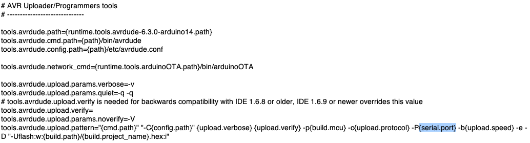
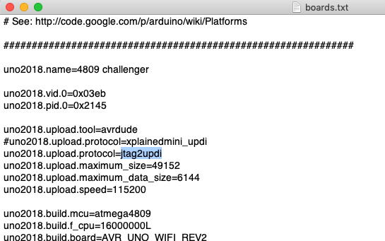
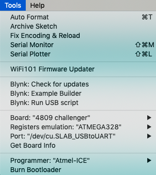
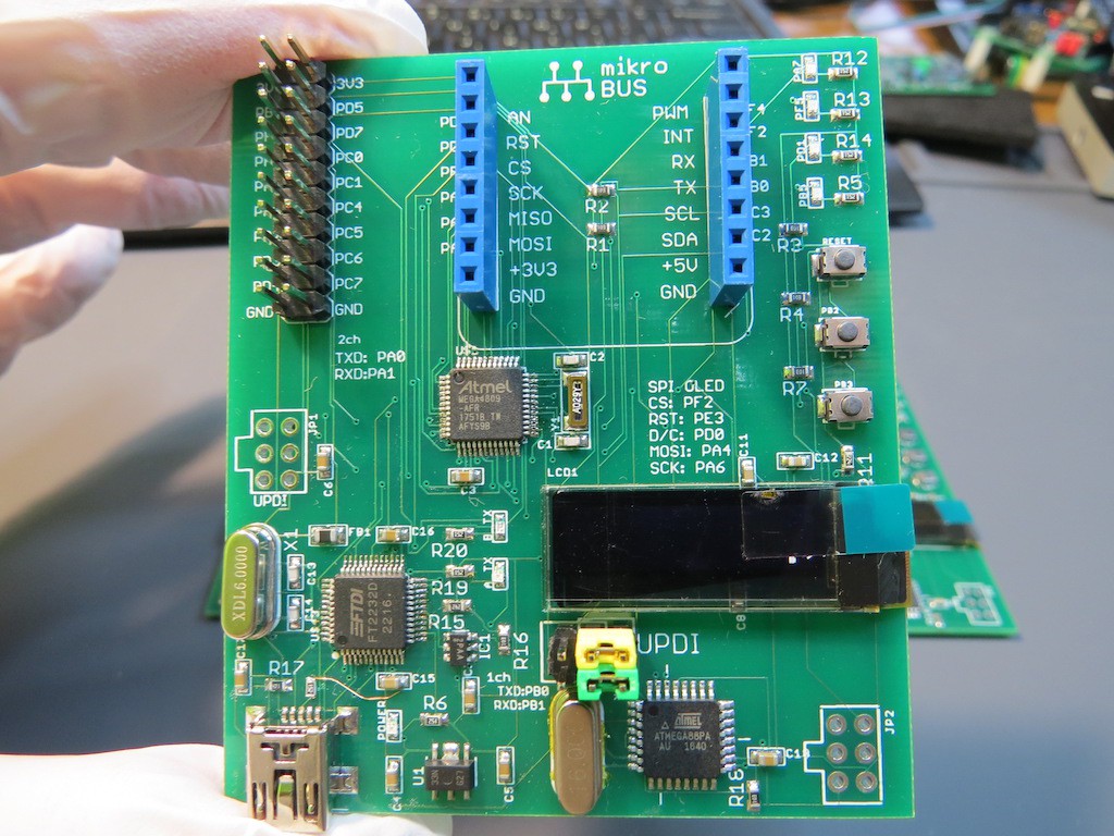
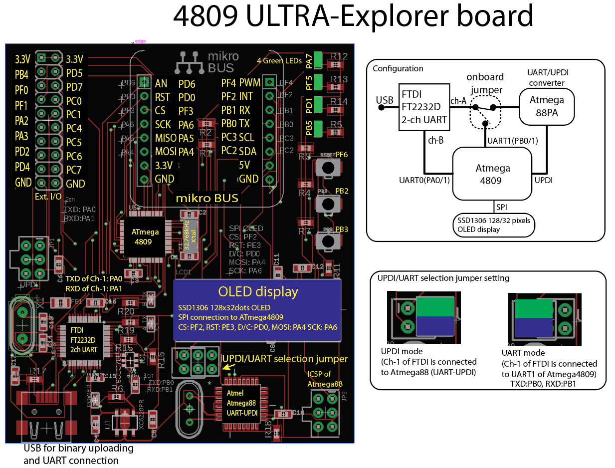
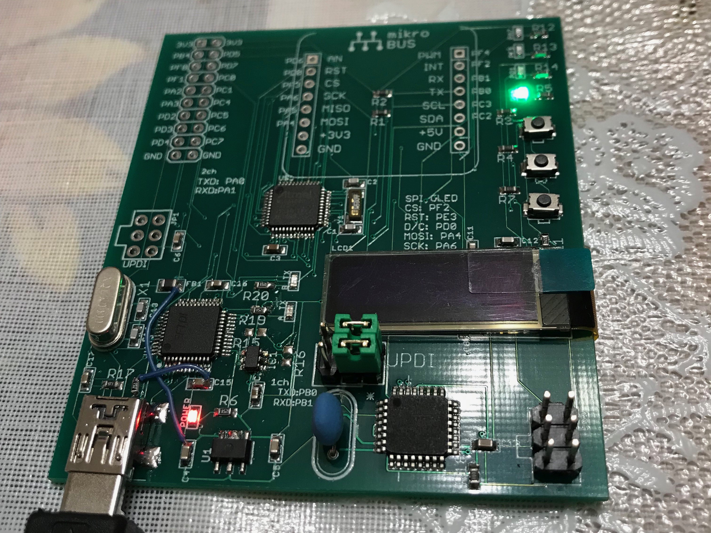
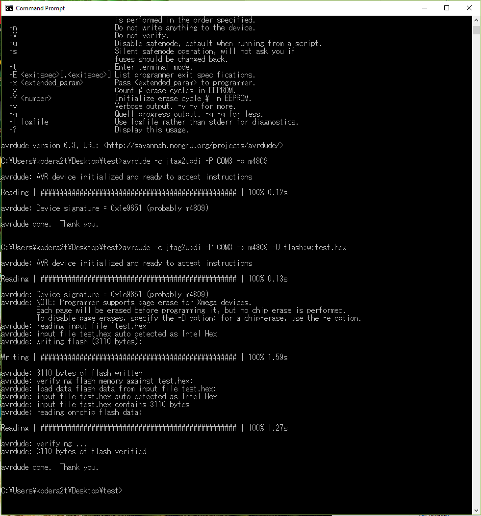
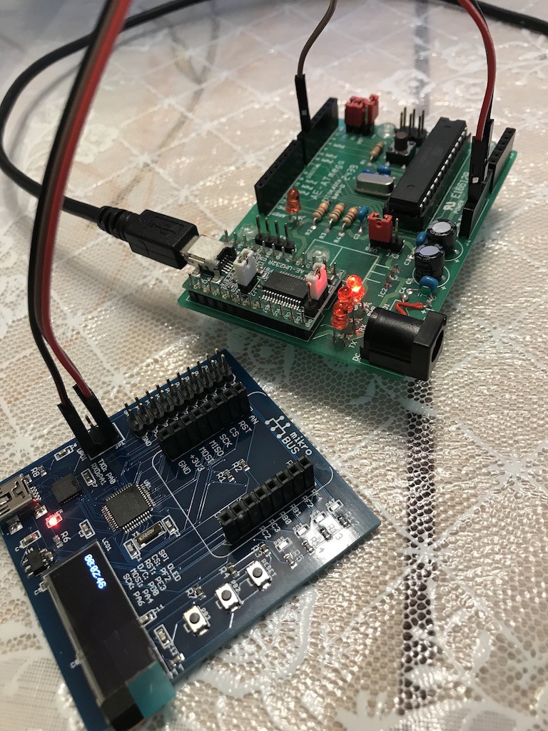
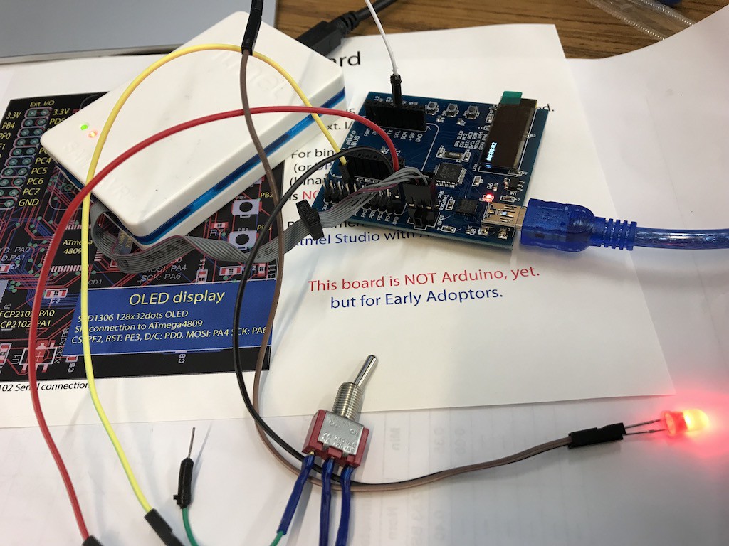
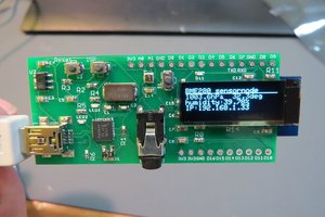
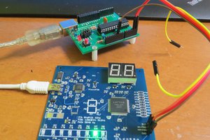
ATMega4809 developing board project
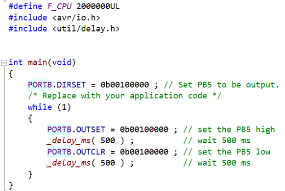
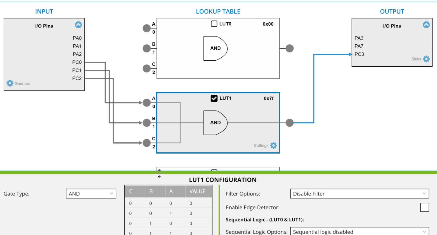
Very new chip by Microchip(Atmel) ATmega4809 has a very unique CPLD like logic and also promised to be applied to next Arduino, why not try!
 kodera2t
Become a Hackaday.io member
Already have an account? Log in.
Just one more thing
To make the experience fit your profile, pick a username and tell us what interests you.
Pick an awesome username
hackaday.io/
Your profile's URL: hackaday.io/username. Max 25 alphanumeric characters.
Pick a few interests
Projects that share your interests
People that share your interests


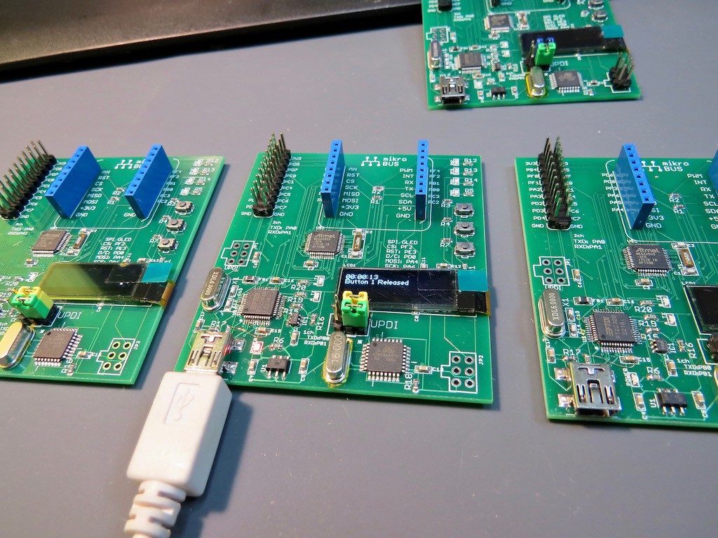


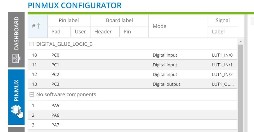


When you are using the Arduino IDE are you able to access all the other pins on your board?
I'm very interested in whether you have expanded the Arduino IDE to utilise your Challenger board. Are you able to access all the uarts for example and still have D0 to D13 available?