 igorfonseca83
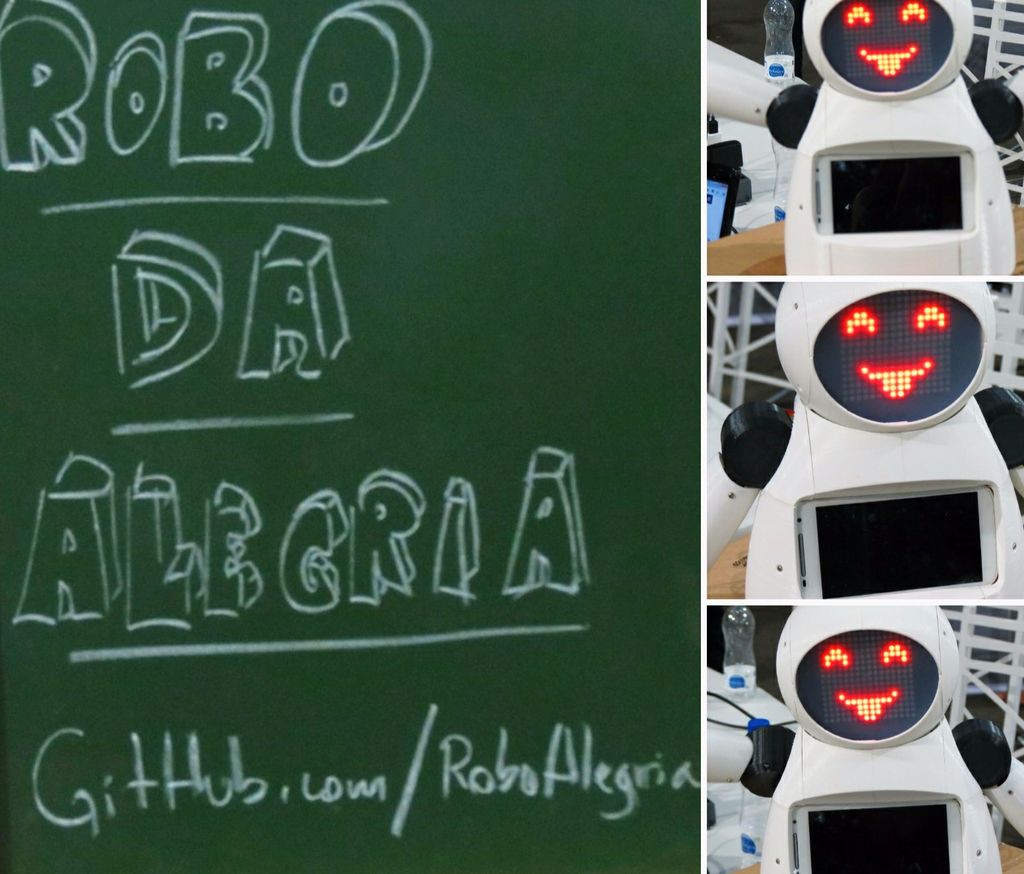
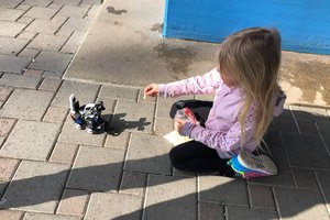
'Robô da Alegria' ('Joy Robot') project was born in 2016, in Baixada Santista region (Brazil), with the objective of developing technology and attracting the community to the maker movement. Inspired by voluntary projects carried out by NGOs in children's hospitals, the project seeks to develop a robot, using open hardware and apen software tools, capable of bringing a little fun to children's hospital environment and contribute to the work of other organizations.
The seed of the project was planted at the end of 2015. After a talk about the creation and development of technology promoted by the Association of Startups of Baixadas Santista (ASEBS). It was idealized a project, without prize in money, but that presented a subject in which people would get involved in an altruistic way, with the goal of helping other people.
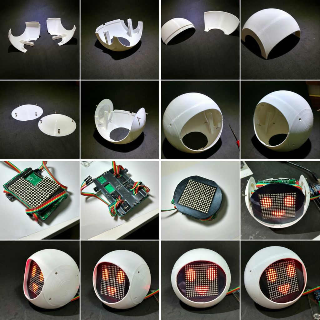
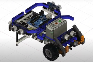
The robot underwent diverse transformations from its initial conception until the present state. From just one head, with mechanical eyes and eyebrows, to its present humanoid form, several iterations were performed, testing different constructive materials and electronic devices. From an acrylic prototype and laser-cut MDF, we moved to a 3D printed body. From a simple interface with two servo motors controlled by Bluetooth, to a body composed of 6 servomotors and 2 motors DC command by a web interface using a Wi-Fi network.
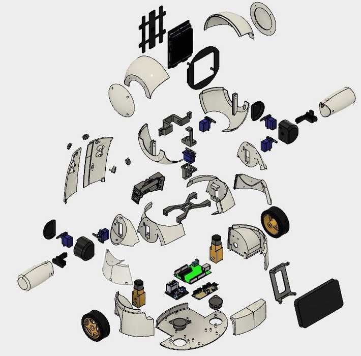
The robot structure has been entirely produced with 3D printing using Fusion 360. In order to enable the production of robot replicas in makerspaces or fab labs, where the maximum time of use of the printers is crucial, the design of the robot was divided in pieces smaller than three hours of printing each. The set of parts is glued or bolted for body mounting.
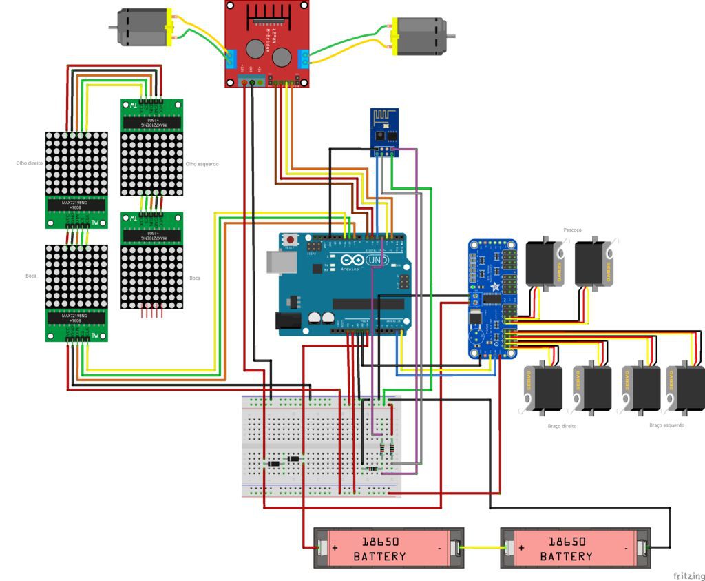
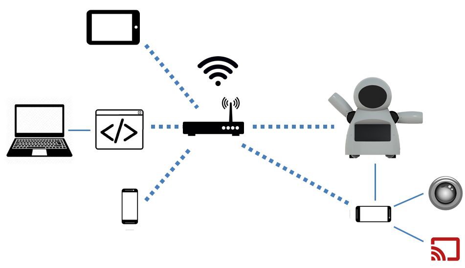
The face, made up of LED arrays, give the robot the ability to express emotions. Servomotors-driven arms and neck give the small automaton the necessary mobility for interaction with users. In the control center of the robot, an Arduino Uno interfaces with all peripherals, including communication with an ESP8266 module, which gives the user the ability to command expressions and movements through any device connected to the same Wi-Fi network.
The Robot also has a smartphone installed in its chest, which is used for transmission of audio and video between the operator of the robot and the children. The device screen can still be used for interaction with games and other applications designed to interact with the robot body.
 Dejan
Dejan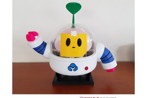
 BINGOBRICKS
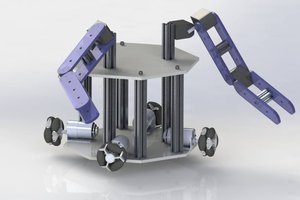
 Valentin Ortega