Close
0%
0%

Flood Fault Circuit Interrupter

Automate the local disconnection of electrical services during a flood.
Enhance the safety of existing residential and commercial systems.

jonJon
Similar projects worth following
Flooding of developed residential and business locations, even those historically unaffected by flood conditions, is becoming an increasingly common problem. The risk of direct damage to structures and property is usually the primary concern, but another factor to consider is the risk of electrocution of a site’s occupants, emergency responders, or even those returning to a location following the flooding event. Addressing this risk is the goal of the Flood Fault Circuit Interrupter.

The goal of this design is to define an active system which can monitor for and, when appropriate, respond to local flood conditions by disconnecting the local electrical service (either in whole or in part).

The Motivation

During the recent flooding associated with Hurricane Harvey a common concern among homeowners trapped in their homes by overflowing bayous and flooded streets was the desire to disconnect individual electric circuits and/or home service as waters begin to threaten homes and their occupants. The dangers of live electrical service in a flooded home were unfortunately highlighted by at least one documented electrocution. This incident, along with the stories of fellow Houstonians standing in heavy rains and/or flood waters as they attempted to manually disconnect electrical circuits inspired this project.

Developed by a team of student engineers based in Houston, the Flood Fault Circuit Interrupter represents the opportunity to address a problem which is both universal as well as personal. Hurricane Harvey was a particularly significant event for Houston. However, even in recent memory Houston has suffered significant flooding, such as during the 2016 tax day floods. Other regions in the Gulf Coast and Caribbean have also suffered through historic hurricanes, with just the past season including infamous storms like Irma and Maria. Looking further out, named storms such as Sandy on the east coast as well as recent devastating rains in Hawaii demonstrate the wide reach of flooding-related challenges. One element which is unfortunately present in so many of these events is the story shared by one of our own team members (whose Harvey-flooded home is pictured in our project page): the challenges and dangers presented by sheltering in a home inundated by flood waters.

The Problem

Currently residential electrical services will, in ideal circumstances, employ passive design techniques to minimize the impact of flooding. These include design choices around the location of service disconnects all the way to how wiring is routed to outlets within the home. Additionally, active measures such as Ground Fault Interrupters and Arc Fault Interrupters may protect only targeted areas of the home as specified in the National Electric Code.  
 

Ultimately, proper disconnection of electrical service can present a significant danger for the end-user in flooding conditions as it requires the operator to approach a service panel (which may be located outside) during heavy rains or, even worse, while standing in floodwaters.

The Solution

The intention of the Flood Fault Circuit Interrupter is to layer upon the aforementioned protections an active monitoring system which would respond to flooding measured around a target location and perform an automated disconnect of electrical service. In addition, the system could be enhanced to allow for operator-initiated activation of the disconnect.

  • 1 × Vista 20p Control Panel Standard home security burglary/fire panel used to monitor sensors for fault conditions (such as wire faults), provide and manage both active and backup power, as well as communicate alarm signals when appropriate. As designed, any security panel capable of supporting 9 wired zones and a 12V alarm output could be used.
  • 1 × Shunt Trip breaker (12V DC input) The shunt trip breaker will mate to an associated circuit breaker and, upon receipt of a 12V DC control input, will throw the breaker to the OFF position.
  • 3 × Double Float Switches Mechanical float switches are used as the remote sensor. The selected design incorporates three double float switches, each of which contain two floats along a single vertical axis.
  • 3 × Outdoor-rated enclosures Enclosures which contain the mechanical float switches should be designed as weather-exposed components allowing water to pass freely into and out of the enclosure while providing physical protection to the mechanical float switches.
  • 1 × EEPROM An electrically erasable programmable read only memory serves as the lookup table to provide a reference between float switch states and fault/warning/flooding conditions.

View all 9 components

  • System Interface and Sub-Panel

    Jon04/23/2018 at 09:14 0 comments

    The security panel keypad acts as the primary system interface. Audio alerts are available via the keypad and statuses are displayed both for individual switches as well as for the warning, fault, and flooding outputs designated for the FFCI system.

    Any individual switch which is either activated or faulted (wire is open circuit) will be identified using a visual alert. A warning status is communicated with a visual alert in addition to an audio alarm when any three (3) of six (6) float switches are activated. This does not remove the system from power. Additionally, a special fault status is defined when the three topmost float switches are activated but the three bottom float switches remain inactive. Lastly, when any four (4) or more of the six (6) total switches are activated the flooding status will be made active which includes both audiovisual alerts as well as an alarm communication to the shunt trip which disconnects the circuit demonstrated by the light bulb. 

  • Float Switch Detail

    Jon04/23/2018 at 09:05 0 comments

    Here is a detail view of the mechanical float switches inside an enclosure. Note how fabric mesh has been applied inside the enclosure to provide basic filtering of small particulates. A heavier gauge mesh has been applied outside the enclosure to provide physical protection. Although the enclosure is designed from multiple metal pieces, the final production version would likely be much simpler to reduce costs.

  • First Complete Mock-Up

    Jon04/23/2018 at 09:01 0 comments

    Here the control panel is connected to all the associated FFCI circuitry.

  • Power Supply on the Cheap

    Jon04/23/2018 at 08:58 0 comments

    Our first power supply for the 5V circuits was a highly efficient switched mode power supply evaluation unit based upon a Texas Instruments chip.

    However, a short-circuit during testing damaged that initial unit and an interim replacement was selected. Given the very low current draw of our 5V components, we selected a power supply recovered from a car charger based upon the MC34063 chip.

  • Mocking up EEPROM, Comparator, and Relays

    Jon04/23/2018 at 08:50 0 comments

    The input comparator circuits, EEPROM, and output relays were connected together and tested prior to interfacing them with the security panel.

    Note the later revision of the comparator circuit. Here the power LED is also generating the reference voltage for the other comparator inputs. Potentiometers are used to fine-tune the voltage at the indicator LEDs to a range appropriate for the LEDs selected (here blue & white 3.3V forward voltage LEDs).

    The test leads wired to ground on the topmost comparator are simply meant to represent a zero (0) voltage closed switch input.

  • Programming the EEPROM

    Jon04/23/2018 at 08:37 0 comments

    The EEPROM was manually programmed using a basic breadboard circuit. This system enabled simple programming, but might be impractical given enough inputs. As built, the system supports six (6) switch inputs with three (3) outputs. This required the programming of 64 entries. The number of entries is simply a function of two to the power of the number of inputs (2^6 = 64).

    LEDs were used to provide a visual indicator of the output levels being programmed. DIP switches were used to select appropriate address values. An RC circuit and momentary switch were used to achieve the necessary specifications required by the EEPROM datasheet to communicate a write mode.

  • Comparator Circuit (1st Revision)

    Jon04/23/2018 at 08:24 0 comments

    A comparator circuit was mocked up to bridge the voltages on the Vista 20p security panel associated with each switch zone. Each comparator was assigned three (3) of the total six (6) switch zone inputs. The outputs of the comparators were each wired to an LED and comparator to provide both a reference voltage value and visual status indicator. The fourth open comparator input on each chip was wired to power an always ON LED.

    The comparator circuit was required because the selected security panel voltages could range from as low as zero (0) volts to twelve volts. Switches were configured using the security system standard of normally open with End of Line (EOL) resistor. In normally open status the circuit voltage would be five (5) volts DC through the specified EOL resistor (2k ohms). A short circuit / closed switch would drive a zero (0) volts level. Open circuit voltage was 12 volts, which would only be present under fault conditions such as cut wires.

    However, as any range outside of 5V could damage the selected EEPROM inputs the comparator was used to compare the voltage reading at the high side on the security panel to a reference voltage (3.3V was selected as an arbitrary value sufficiently between zero and 5). 

View all 7 project logs

Enjoy this project?

Share

Discussions

Jon wrote 05/17/2018 at 18:10 point

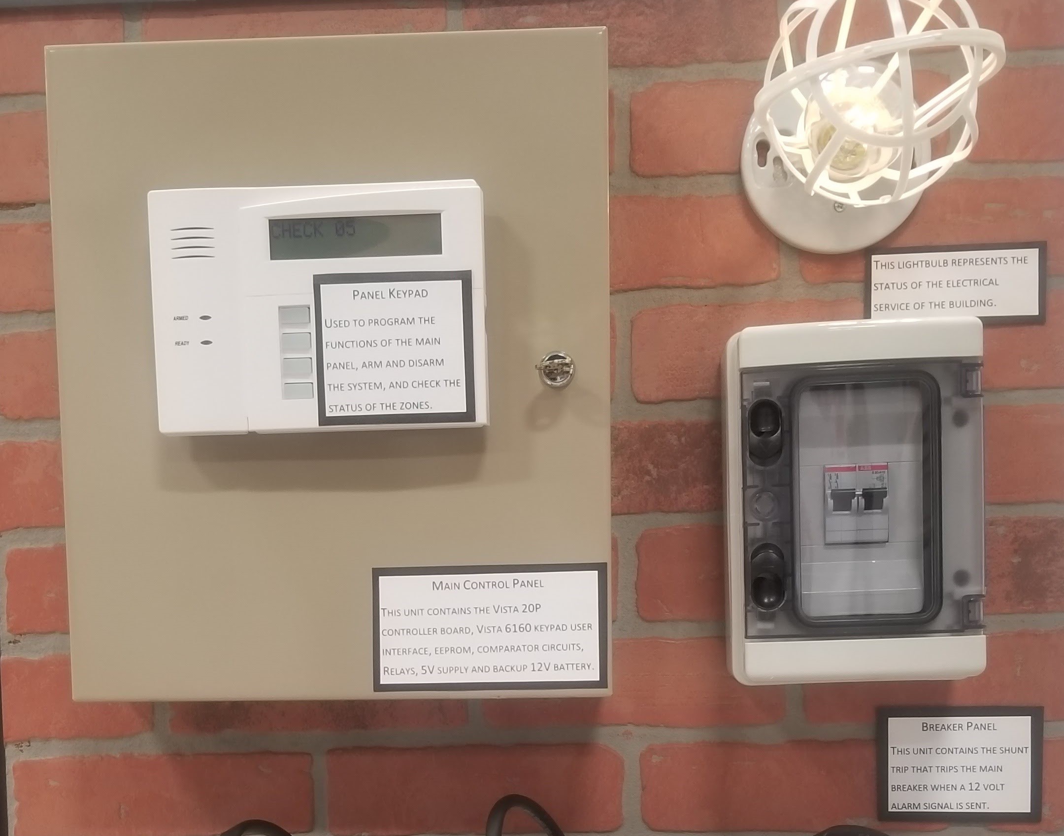
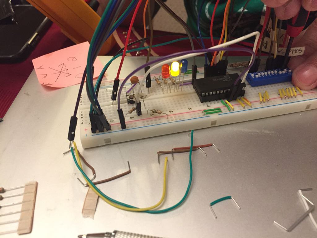
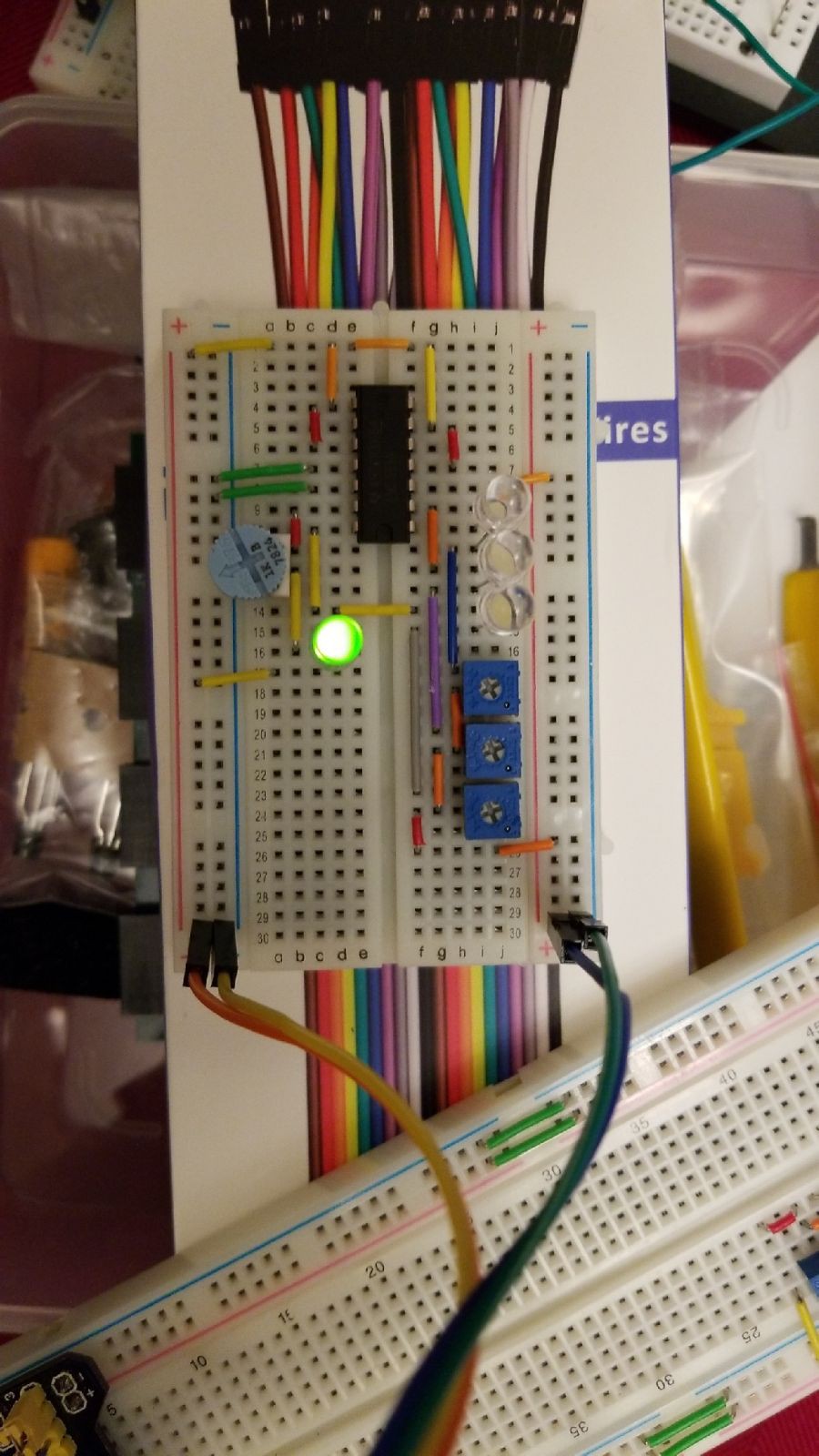
That's a great idea for another project log. Short version: if you look in the block diagram model, the EEPROM is the Logic element of the system and determines when FAULT, WARN, and ALARM states are communicated to the control panel.

The EEPROM stores the appropriate output response to each of the 64 possible combinations of input switch states (recall that there are six switches total). The output side of the EEPROM connects back to three (3) relays which are then connected to three security panel zones dedicated for each state/response. FAULT and WARN trigger an audible alarm only on the control panel in addition to a visual warning (the panel will display FAULT or WARN). ALARM includes the audible and visual alarm and also sends a trigger signal to the shunt trip breaker pulling the breaker to OFF.

The switches are connected to the security control panel directly but security control panels have relatively limited logic functionality. This will likely need to be another dedicated project entry so that I can see if any Hackaday contributors have additional insights. There are, however, other advantages provided by the integration of the security panel as the controller (around power management and line fault monitoring).

My next project entry will be about a security element which is my primary target for integration (a Zone Expander). However, I'll try to follow up with two entries. One will be on the Karnaugh maps / lookup tables which document the logic rules we used. From there I'll detail out the EEPROM as implemented. Please feel free to reply back with any other documentation notes I could add which you think might be helpful?

  Are you sure? yes | no

Gabriel wrote 05/18/2018 at 12:33 point

Thank you for the explanation.

So the 6 switches control the address inputs, and the resulting output byte control the relays, alarms etc.... if so, thats a super cool way of building a programable state machine! Clever!

I dont remember EEPROMS well enough, but dont you need a clock to "latch" the address and get an output?

  Are you sure? yes | no

Jon wrote 05/18/2018 at 16:15 point

You got it right on both counts:

1. We use a single parallel EEPROM instead of tons of glue logic chips. This is the simplest option before progressing to some kind of programmable logic. I actually spent a weekend learning basic VHDL and programming a Complex Programmable Logic Device (CPLD) to work in the project before realizing how overkill such a design would be. The only advantage it imparted as implemented would have been power savings but these devices are all low power draw even when latched ON all the time (see more on that below). Of course, something like a CPLD could add a ton of potential for design flexibility, but it was beyond the scope of options we'd considered thus far.

2. EEPROMs can be left active so they're essentially instant on/response. The actual response time would be measured on the order of around 100 nanoseconds; note that the polling signals generated by the security control panel are on the order of 10 milliseconds to over a second(!).

  Are you sure? yes | no

Gabriel wrote 05/18/2018 at 17:40 point

awesome use of the eeprom! I will keep that in mind!

  Are you sure? yes | no

Gabriel wrote 05/17/2018 at 02:46 point

can you please give more detail on how the eeprom is used? I dont understand its function in this proyect.

  Are you sure? yes | no

Similar Projects

Does this project spark your interest?

Become a member to follow this project and never miss any updates