The Power PACks are modules designed around the PAC52xx family of devices and are all meant to drive motors of different topologies, sizes and algorithm styles. All of these modules are very similar in construction, albeit there are different variants, designers can take advantage from.
For example, you could design an application to work with 12V DC, or one to work with 120V DC. Needless to say, the implementation would be different as it would need to accommodate for the different voltages. In the same fashion, any given application may work flawlessly with a small current such as 5A RMS, whereas a larger one may require currents in the many dozens of amps, with incursions into the 100A range. Again, choosing the components carefully on a per application basis will yield expected results.
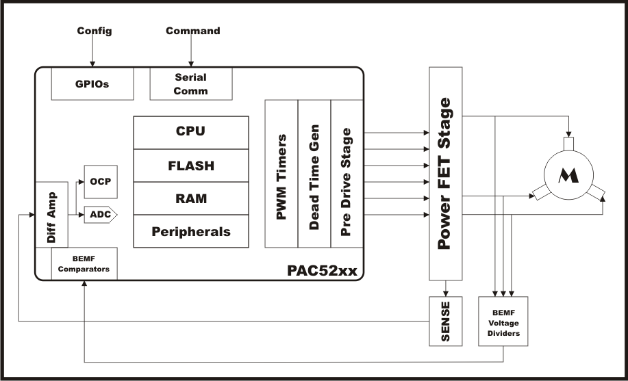
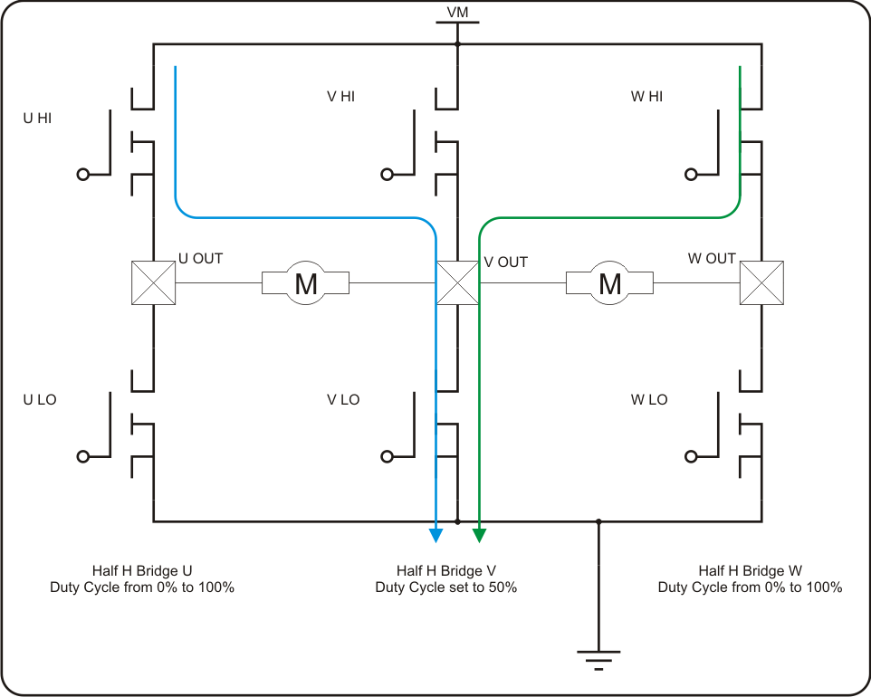
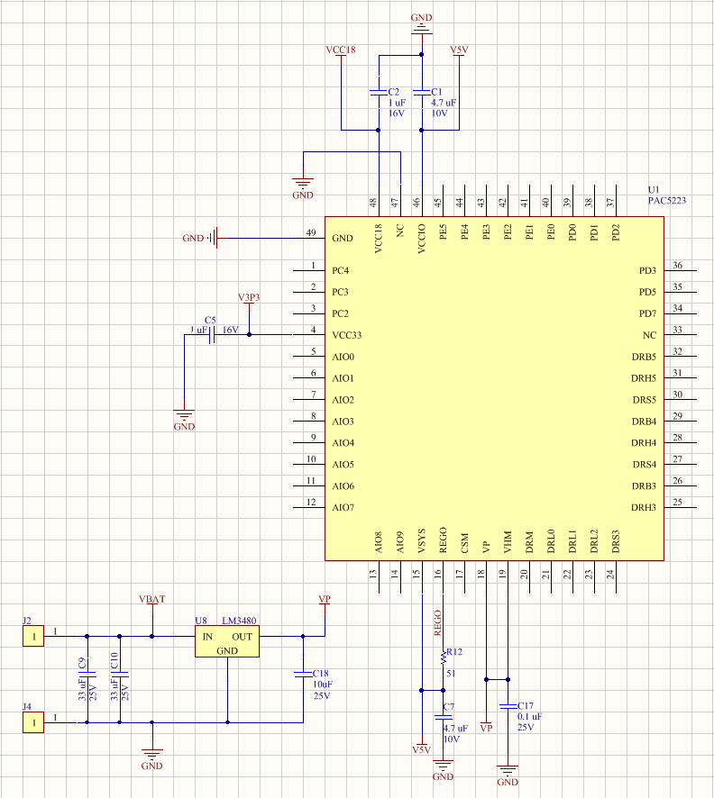
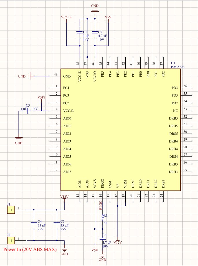
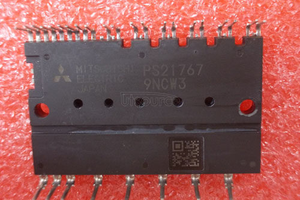
With that being said, all of these applications block diagrams will look nearly identical! You will see a PAC52xx Microcontroller/Pre Drive power stage device. This device will drive the six FETs which form the three phase inverter. At the bottom of the tri phase inverter, you will have one or three SENSE resistors which the PAC52xx will use to gather motor current information. Also, each phase output will have a voltage divider the PAC52xx will use to gather BEMF voltage information. With these currents and voltages, the microcontroller will run a piece of FW which will then decode the motor rotor's position and cause the required commutation.
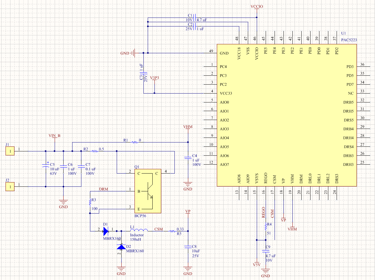
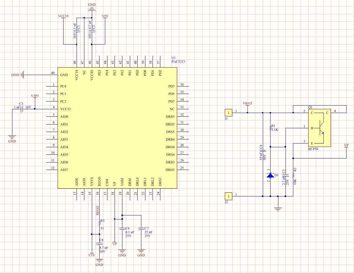
Other than the MCU, power FETs and current SENSE Shunts, you will need a small number of passive components such as resistors, capacitors and diodes. These are used to provide coupling to internally generated rails (VP, VSYS, V3P3, VCCIO, and V1P8 ceramic capacitors), filter the different analog signals (AIOxy ceramic caps and resistors), protect the pre drive power stage from negative voltages (DRS diodes and resistors), limit gate current (gate drive resistors and diodes), apply bootstrap voltages (DRB diodes and ceramic capacitors), a power resistor for the VP to VSYS LDO (REGO resistor), and the Buck converter components (diodes, a cheap NPN transistors, an inductor, resistors and caps), etc.
Pretty much everything else is included INSIDE of the PAC52xx device! That is the microcontroller, the program memory, the ADC, the linear regulators, the Buck Converter, the Differential Amplifiers, the BEMF comparators, the multiplexers, the wake up controller, the Pre Drive Stage, which in essence is all you need to drive your 3 phase BLDC or PMSM motor! Well, of course the other missing component is the code, but that also goes inside...
It has never been easier to drive a 3 phase Brushless DC motor!

 Electroniclovers123
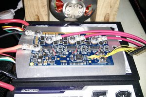
 Jarrod
 Michael Ratcliffe
The PAC52xx devices are mega awesome! The best thing they have to offer is that they pack all of the circuitry you need to drive a tri phase inverter for controlling tri phase bldc motors. That is, they include all of the power rails, differential amplifiers, comparators, ADC, pre drive stage to drive external FETs, etc. On top of that, there is an ARM Cortex M0 MCU with 32 KB of Flash and 8 KB of RAM which permits pretty much any algorithm to be implemented. I will soon post videos on how these modules operate.