Close
0%
0%

The DaisyDriver

An open source motor controller designed for use in automating scientific experiments.

Similar projects worth following
Automation transformed the way that industry was able to produce goods for market. Incorporating automation into scientific practice will allow us to overcome many of the limitations that are commonplace in scientific experiments, especially in developing nations. Inspired by the work of Waterscope (http://www.waterscope.org/), who are helping make safe water available in Tanzania using a low cost 3D printed microscope, we designed a motor controller to make automating experiments and tests easy.

The Challenge: Automating Science

The validity of scientific experiments depends entirely on their repeatability. Unfortunately for science, humans are not good at repeating their actions reliably and precisely, and can only manage to do so after training. There are many situations where opportunities for training are limited, such as in developing nations, where tests are often required to determine if water is safe to drink. In such cases, the end result is often that water goes untested, resulting in the spread of disease and in avoidable stress on the healthcare system.

In developed nations, automation is commonplace in industry, where it has undoubtedly contributed to many increases in the quality and volume of production. Whilst science has enjoyed the benefits of modern computers, which can be thought of as machines for automatic calculation, science has been slow to adopt the use of machines for automatic experimentation. In this case, the outcome has been that our enquires are limited to those that can be undertaken by a human. Experiments that are too time-consuming or difficult to do are simply not done, or altered (where possible) to suit the constraints of the researcher. 

In both of these cases, questions that are important to human life are left unanswered because of human limitations. In order to answer these questions, we must move towards a world where automation is commonplace in science. 

A Solution: The DaisyDriver

 In contrast to humans, robotic machines are capable of repeating their actions tirelessly, often with much greater speed and precision than a human operator. The disadvantage that automated systems carry is a high set-up cost and inflexibility to change. This drawback is a major problem for scientific experiments, which can be immensely varied in their requirements. The DaisyDriver project aims to overcome these drawbacks, by creating a system of modular motor drivers that can be used by scientists and citizens alike to automate their experiments. 

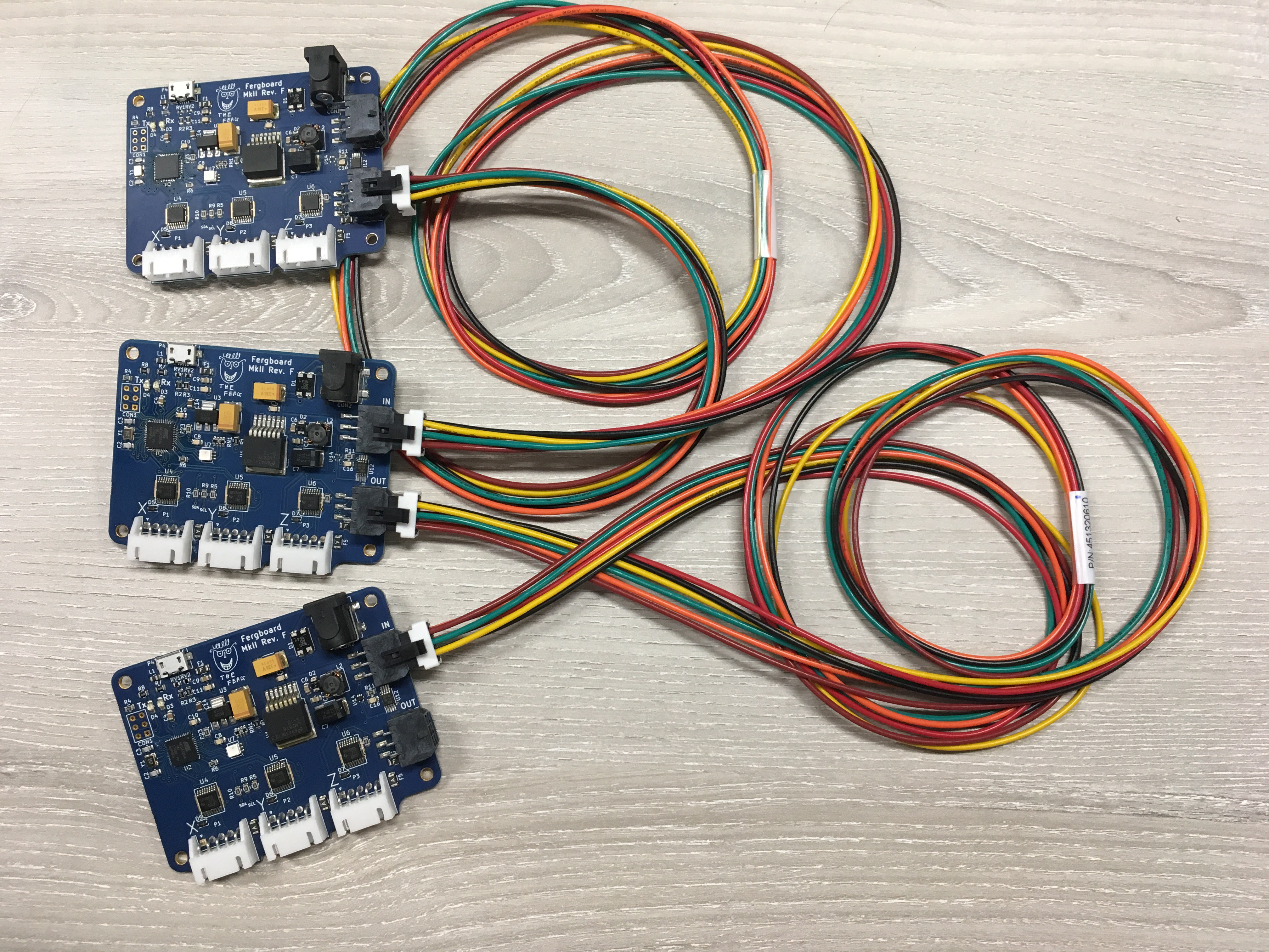
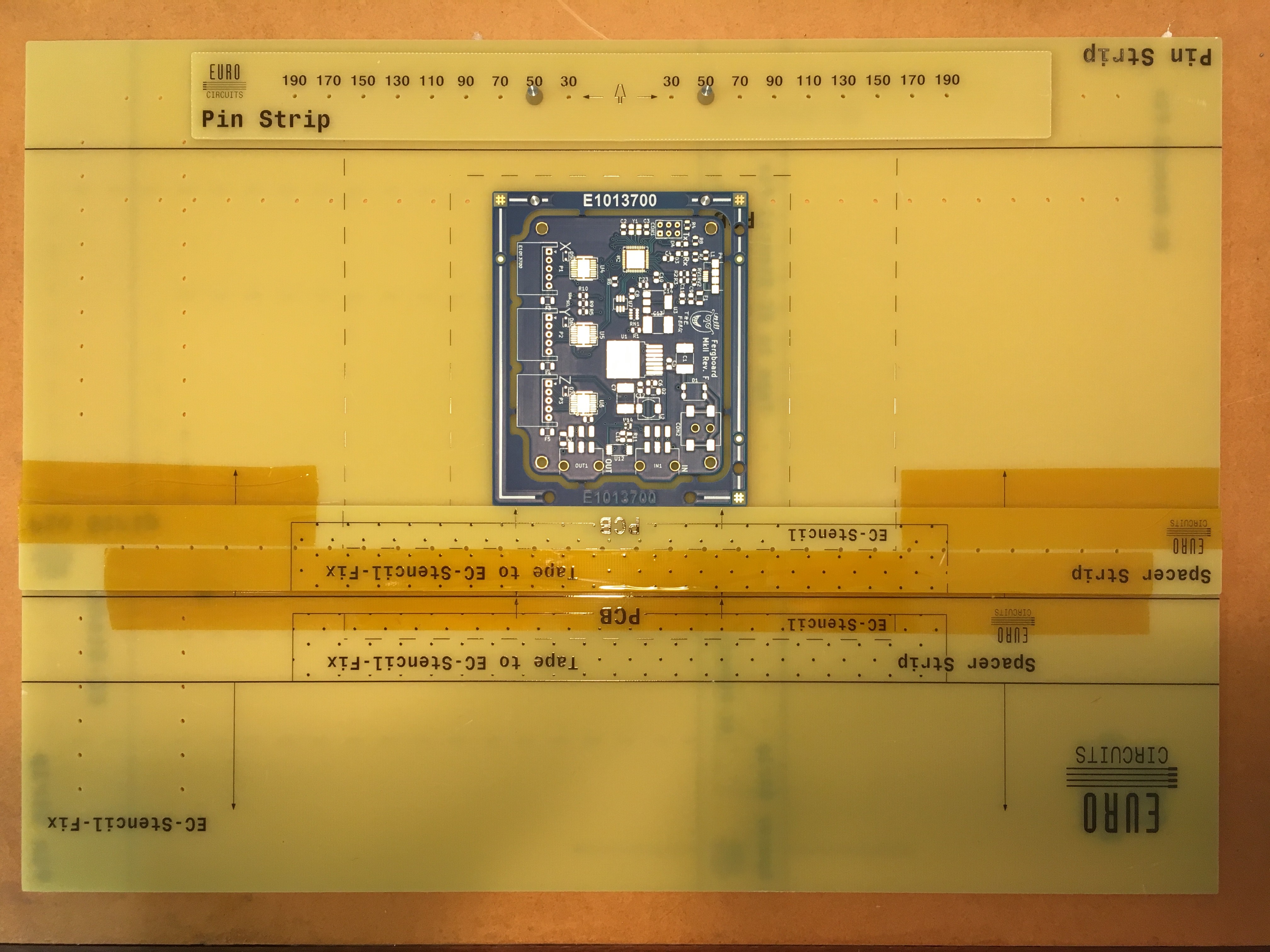
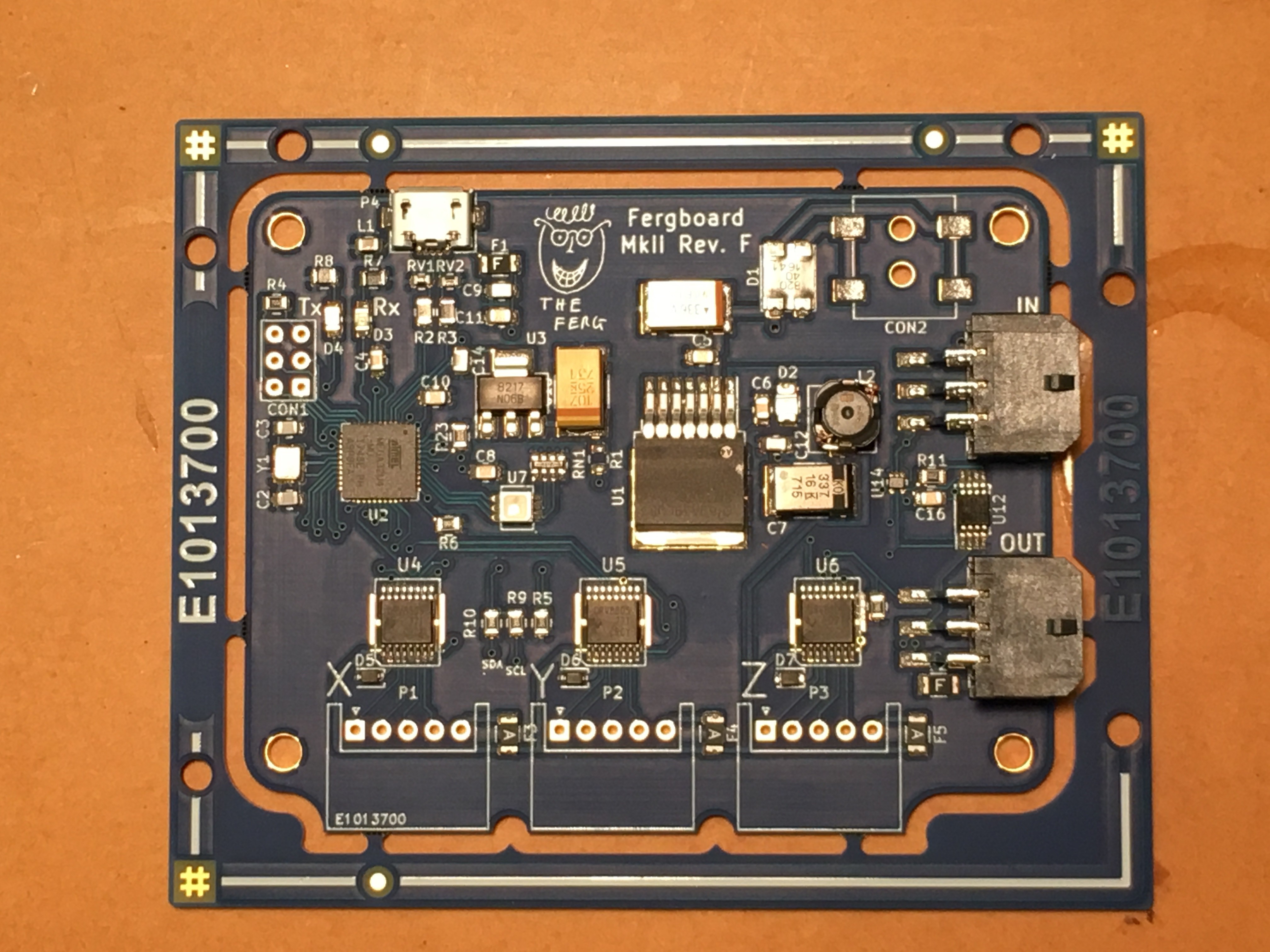
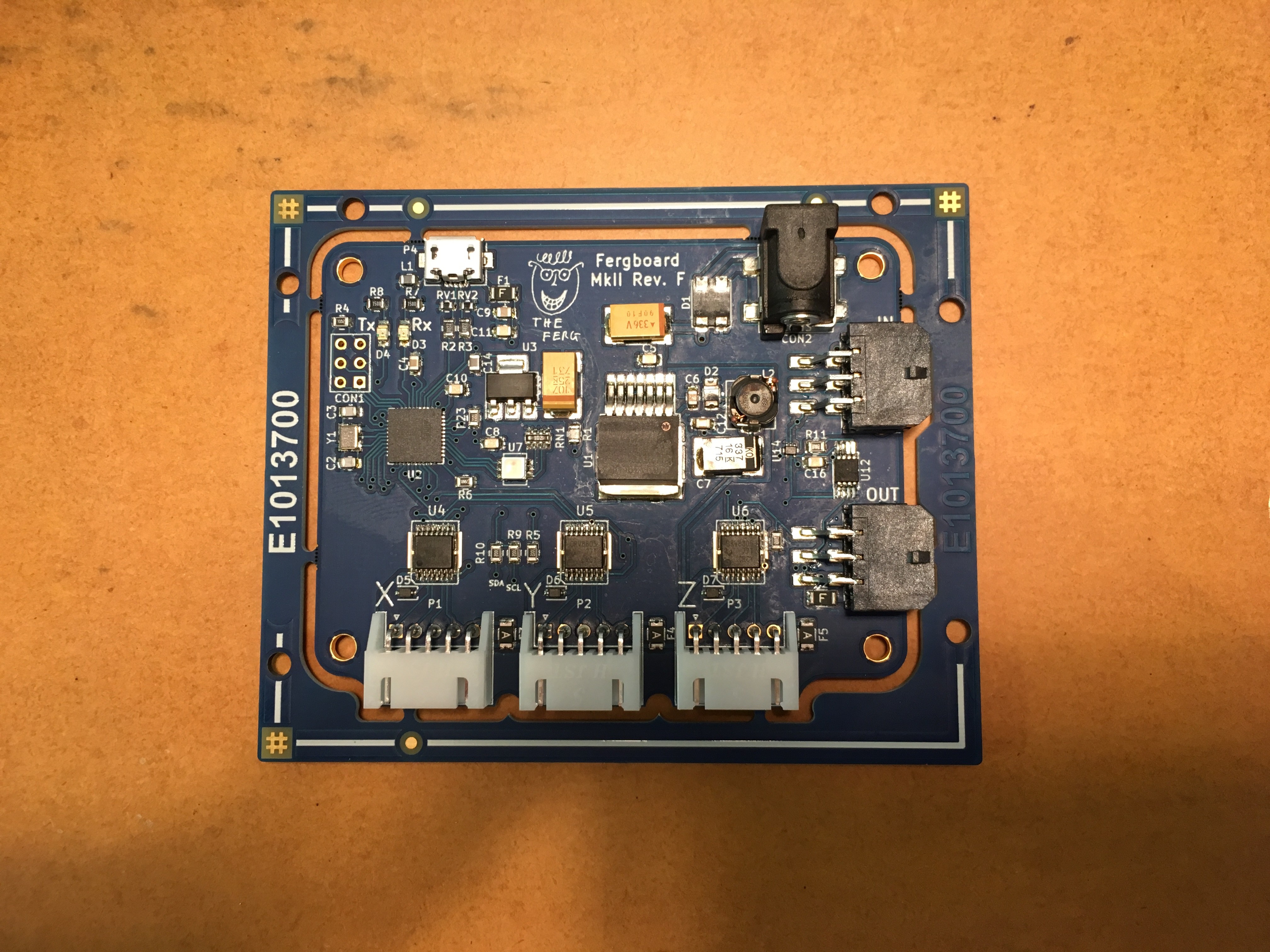
The DaisyDriver system has two components; the FergBoard motor drivers and the DaisyDriver GUI. The FergBoard drivers (pictured below) are capable of controlling three unipolar stepper motors each, over a serial interface using simple alphanumeric commands. The FergBoards can be connected together in order to extend the number of axes that are controlled by the same interface. For example, if a system required twelve axes to be controlled simultaneously, four Fergboards could be connected together to act as a singe twelve axis controller. The flexibility offered by such a modular system, coupled with the ability to specify the motion required in an experiment programmatically, provides a platform for automating experiments that is both robust and scalable. 

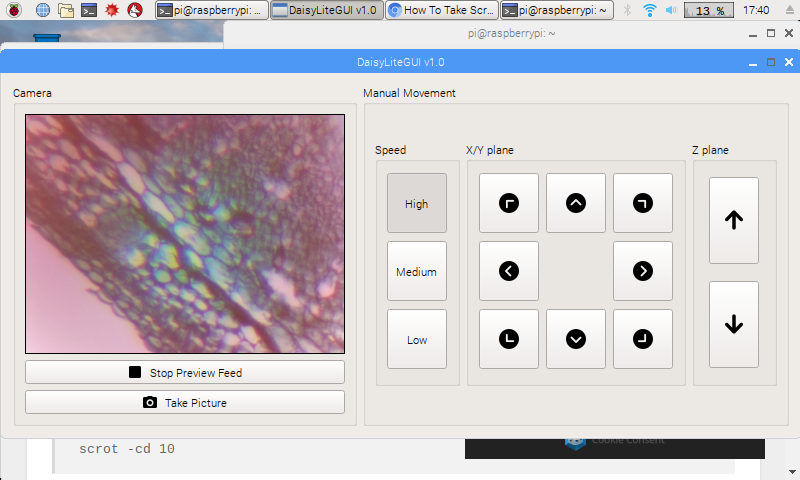
The DaisyDriver GUI is a simple graphical interface to the FergBoard, designed to work with the Raspberry Pi and OpenFlexureScope (https://github.com/rwb27/openflexure_microscope) to allow a user to set up and control their experiments from a computer with instant feedback.

fergboard_2v2.ino

An alpha version of the code that incorporates automatic i2c addressing and networking features.

ino - 11.23 kB - 09/21/2018 at 12:11

Download

Arduino-SerialCommand-Fergboard.rar

The library required to use the Fergboard code; a modified version of the SerialCommand library found at https://github.com/scogswell/ArduinoSerialCommand

RAR Archive - 10.97 kB - 09/21/2018 at 12:06

Download

OneWire_Ordering.ino

A code fragment that implements the automatic i2c addressing routine

ino - 2.39 kB - 06/03/2018 at 13:32

Download

fergboard_2v1.ino

The most complete version of the Fergboard Firmware

ino - 9.49 kB - 06/03/2018 at 13:31

Download

datasheets.rar

Contains the datasheets for some of the parts used in the FergBoard

RAR Archive - 10.44 MB - 06/03/2018 at 13:28

Download

View all 6 files

  • 1 × Raspberry Pi 3B or 3B+ A single-board computer, to do your calculation in a compact package
  • 1 × FergBoard A modular motor driver, to make everything move
  • 1 × OpenFlexureScope A 3D printed microscope, to inspect samples. See (https://github.com/rwb27/openflexure_microscope) for more information
  • 3 × 28BYJ-48 12V stepper motors Motors to automate motion of the OpenFlexureScope Axes
  • 1 × Raspberry Pi Camera V2 A camera, to see your samples

  • Announcing the DaisyDriver

    fr29306/04/2018 at 11:52 0 comments

    The DaisyDriver project has now reached a significant milestone; full integration of the hardware and software components. Watch the video below to see us using the DaisyDriver to have a look around a cotton stem.

View project log

  • 1
    Installing the DaisyDriver GUI for Automated Microscopy

    You Will Need:

    • 1 Raspberry Pi 3B or 3B+ with the latest version of Raspbian Stretch installed
    • 1 PiCamera v2
    • 1 FergBoard
    • 1 OpenFlexureScope (with motor attachment lugs)
    • 3 28BYJ-48 motors 

    DaisyDriver or DaisyDriverLite?

    There are two versions of the GUI, DaisyDriver and DaisyDriverLite. DaisyDriver is the fully featured version of the software, with features for moving the microscope and scheduling time series image captures. DaisyDriverLite is a pared-down version of the software, featuring only  simple image previews and microscope movement controls. The installation procedure for both versions is similar, the version given below works for DaisyDriver. If you wish to install DaisyDriverLite, change all instances of "DaisyGUI" to "DaisyLiteGUI".

    More information, as well as the source code and build history for both versions is available at https://github.com/OpenDaisy-Microscopy


    Installation Procedure

    1. Open terminal window and navigate to the directory you want to install DaisyGUI
    2. Enter the command <pre class="hljs bash">git <span class="hljs-keyword">clone</span> https:<span class="hljs-comment"><a target="_blank" rel="noopener noreferrer" href="<a target="_blank" rel="noopener noreferrer" href="//github.com/OpenDaisy-Microscopy/DaisyGUI.git">//github.com/OpenDaisy-Microscopy/DaisyGUI.git</a>"><a target="_blank" rel="noopener noreferrer" href="//github.com/OpenDaisy-Microscopy/DaisyGUI.git">//github.com/OpenDaisy-Microscopy/DaisyGUI.git</a></a></span></pre>
    3. Once this has finished, navigate into the DaisyGUI folder using <pre class="hljs bash"><span class="hljs-built_in">cd</span> DaisyGUI</pre>
    4. Then run the install script to ensure all required dependencies are installed <pre class="hljs bash">bash <span class="hljs-operator"><span class="hljs-keyword">install</span>.sh</span></pre>
    5. Now, to open DaisyGUI use the command <pre class="hljs bash"><span class="hljs-title">python3</span> DaisyGUI.py</pre>
    6. When opening DaisyGUI subsequently, you will need to navigate to this directory again and run the command in step 5.

  • 2
    Assembling Fergboards Using a Hotplate

    You Will Need:

    • 1 Fergboard PCB
    • (optional) 1 FergBoard solder stencil
    • 1 BoM, as listed in the FergBoard design files
    • 200 ml Isopropanol
    • Solder paste
    • 2 hotplates capable of maintaining temperatures of 50◦C 􏰆 to 􏰆 400◦C
    • 1 steel or aluminium plate large enough to support the Fergboard
    • 2 pairs of spade tipped tweezers
    • 1 pair safety glasses
    • 1 pair heat resistant gloves.

    Soldering Procedure:

    1. Set one hotplate next to the other and ensure the tops are clean and free from distortion. Turn one on to 100◦C, and the other to 350◦C. Allow ample time for them to come to temperature
    2. Apply solder paste using either a stencil or an applicator syringe. A stencil is recommended due to the higher precision of paste deposition it off􏰃ers, as well as the superior evenness of the applied paste thickness.
    3. Place surface mount components on the board, noting that slight errors in the positions of the components will generally be corrected by the surface tension of the solder at re􏰄flow.
    4. Wearing the safety gloves and glasses, position the metal plate on the 100◦C plate, and allow it to come to temperature. Note that thermal distortion of the plate may initially occur, which can be corrected by pressing down on the corners of the plate with the tweezers.
    5. Once the plate has come to temperature, place the PCB on it and wait for up to two minutes for it to heat up. During this time, thermal distortions can be corrected by pushing gently on the corners of the PCB, in the same manner as step 4. The solder paste may change slightly in appearance, and the fl􏰄ux may activate.
    6. Once the PCB has come to temperature on the 100◦C metal plate, transfer the PCB on the metal plate to the 350◦C hotplate. Correct thermal distortions as before, and observe the pads of the PCB carefully. The solder paste should begin to melt within 2 minutes, and be fully molten within 3. Any pads that do not re􏰄flow within 3 minutes can be corrected by hand using a rework station. Take care also that the silkscreen is not scorched before the PCB refl􏰄ows; if this occurs, then a redesign of the board may be necessary.
    7. Transfer the PCB and the metal plate back to the 100◦C hotplate for approximately one minute and then to a wire rack. This step is to avoid thermal shock to the components. Once the PCB has cooled to around 50◦C, the metal plate can be safely extracted.
    8. Repeat steps 1-7 with all further PCBs to be soldered, then turn off􏰃 the hotplates and allow them to cool. Wash the PCBs with isopropanol and allow to dry.
    9. Solder any remaining through-hole components in by hand.
    1. 3
      Programming A FergBoard

      You Will Need:

      • 1 Arduino ISP or UNO
      • 1 FergBoard
      • 1 Micro USB B to USB A cable
      • 1 computer terminal loaded with the Arduino IDE 

      Programming your Boards

      Programming FergBoards is done in two steps; an initial bootloader burn that only needs to be performed once, and a subsequent programming step where the actual program is loaded. 

      1. Programming the bootloader: This is most easily performed using an Arduino ISP programmer (https://store.arduino.cc/arduino-isp), which can be connected to the ICSP header of the Fergboard directly. From there, load the Arduino IDE, select Arduino Micro from the Tools > Boards menu, and press Burn Bootloader from the Tools > Boards menu. Alternatively, an Arduino Uno or similar can be used as a programmer, by following the Arduino instructions given here (https://www.arduino.cc/en/Tutorial/ArduinoISP).
      2. Writing the Code: Once the bootloader has been written initially, writing the actual code is simply a case of connecting the Fergboard to a USB port using the USB micro connector, selecting Arduino Micro from the Tools > Boards menu, and uploading the code you wish to run on the Fergboard. Any subsequent revisions can be uploaded directly to the fergboard without reloading the bootloader.

    View all 4 instructions

    Enjoy this project?

    Share

    Discussions

    Similar Projects

    Does this project spark your interest?

    Become a member to follow this project and never miss any updates