Close
0%
0%

Ultra-Low Power LiPo Charger via Energy Harvesting

Super-small BQ25504-based device charges a LiPo battery at ~7 mA using an inexpensive solar cell in direct sunlight

Similar projects worth following
I have been using the ESP8285 and other MCUs for a lot of environmental sensing projects and battery life is a big issue, even for the relatively low power STM32L4. The competing priorities of small size and long life are hard to manage without an oversize battery or having to recharge after just a few hours. Neither is really acceptable for wearable applications or those demanding remote monitoring. In addition to beating down energy usage with various low power strategies, one solution is to harvest energy from the environment. High-efficiency, inexpensive solar cells make this a logical choice for remote applications like environmental data loggers, and the BQ25504 makes it easy to power an MCU with the sun! The low (>330 mV) cold start threshold even allows practical energy harvesting from indoor lighting as well.

This is a product for sale at Tindie that I designed and use in various projects, including my SensorTile project where I have described its performance in detail.

From the Tindie product page:

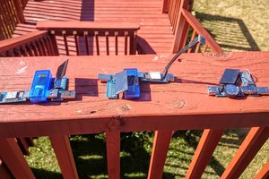
This is a small (0.5 x 0.5 inch) breakout board for Texas Instrument's BQ25504 Ultra Low Power Boost Converter with Battery Management for Energy Harvesting Applications.

From the datasheet: "The bq25504 device is the first of a new family of intelligent integrated energy harvesting nano-power management solutions that are well suited for meeting the special needs of ultra low power applications. The device is specifically designed to efficiently acquire and manage the microwatts (µW) to milliwatts (mW) of power generated from a variety of DC sources like photovoltaic (solar) or thermal electric generators. The bq25504 is the first device of its kind to implement a highly efficient boost converter/charger targeted toward products and systems, such as wireless sensor networks (WSNs) which have stringent power and operational demands. The design of the bq25504 starts with a DC-DC boost converter/charger that requires only microwatts of power to begin operating."

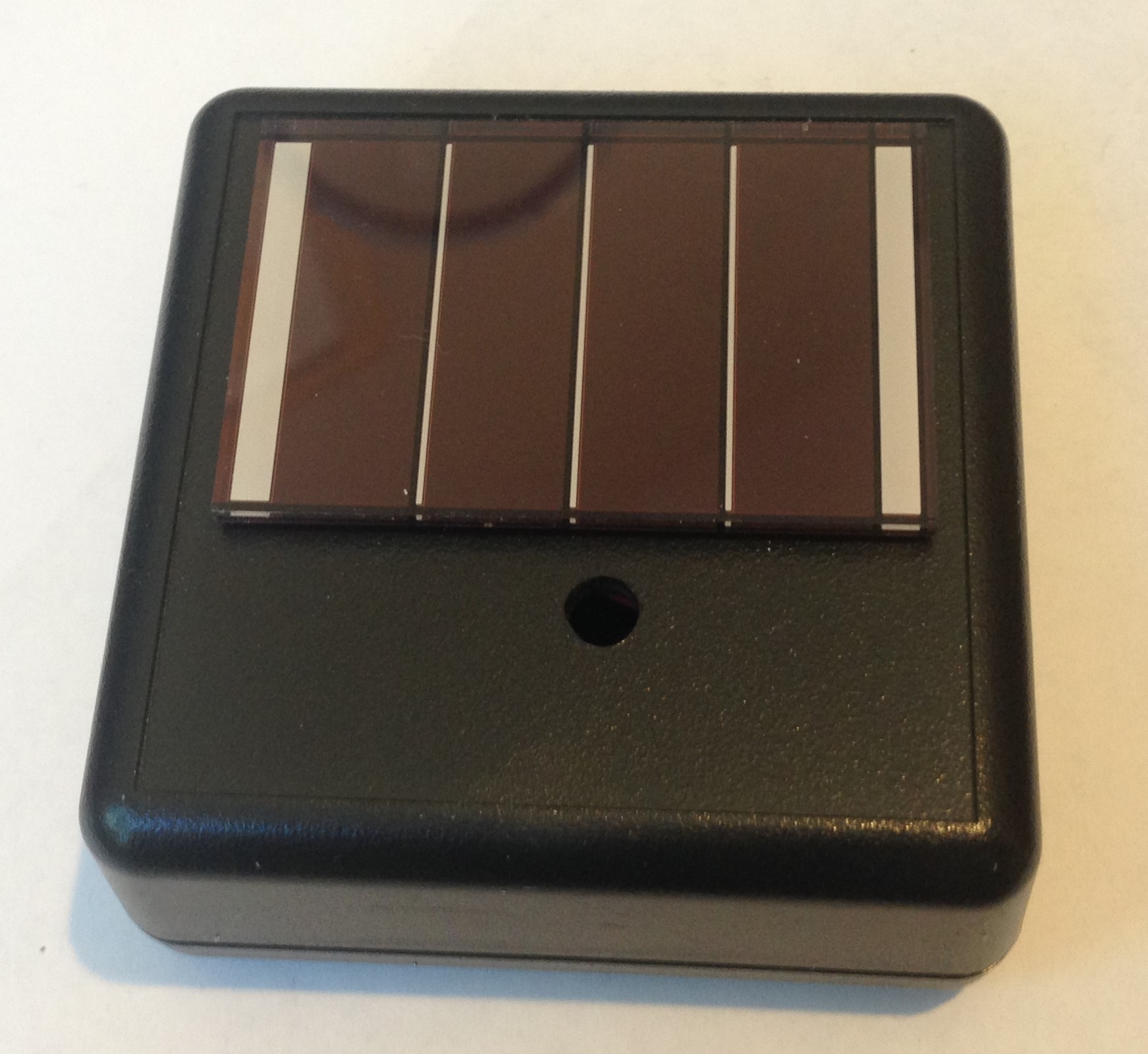
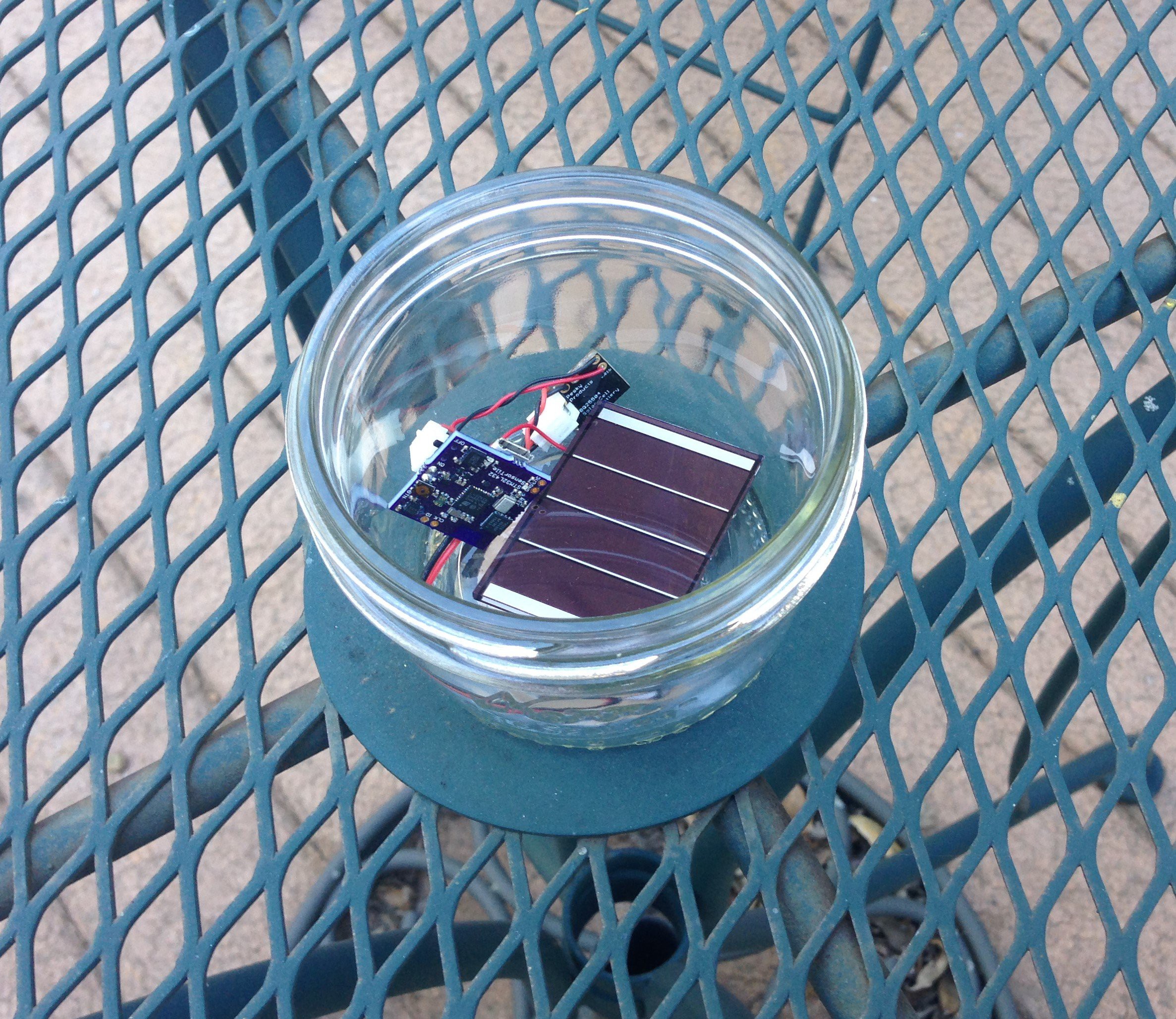
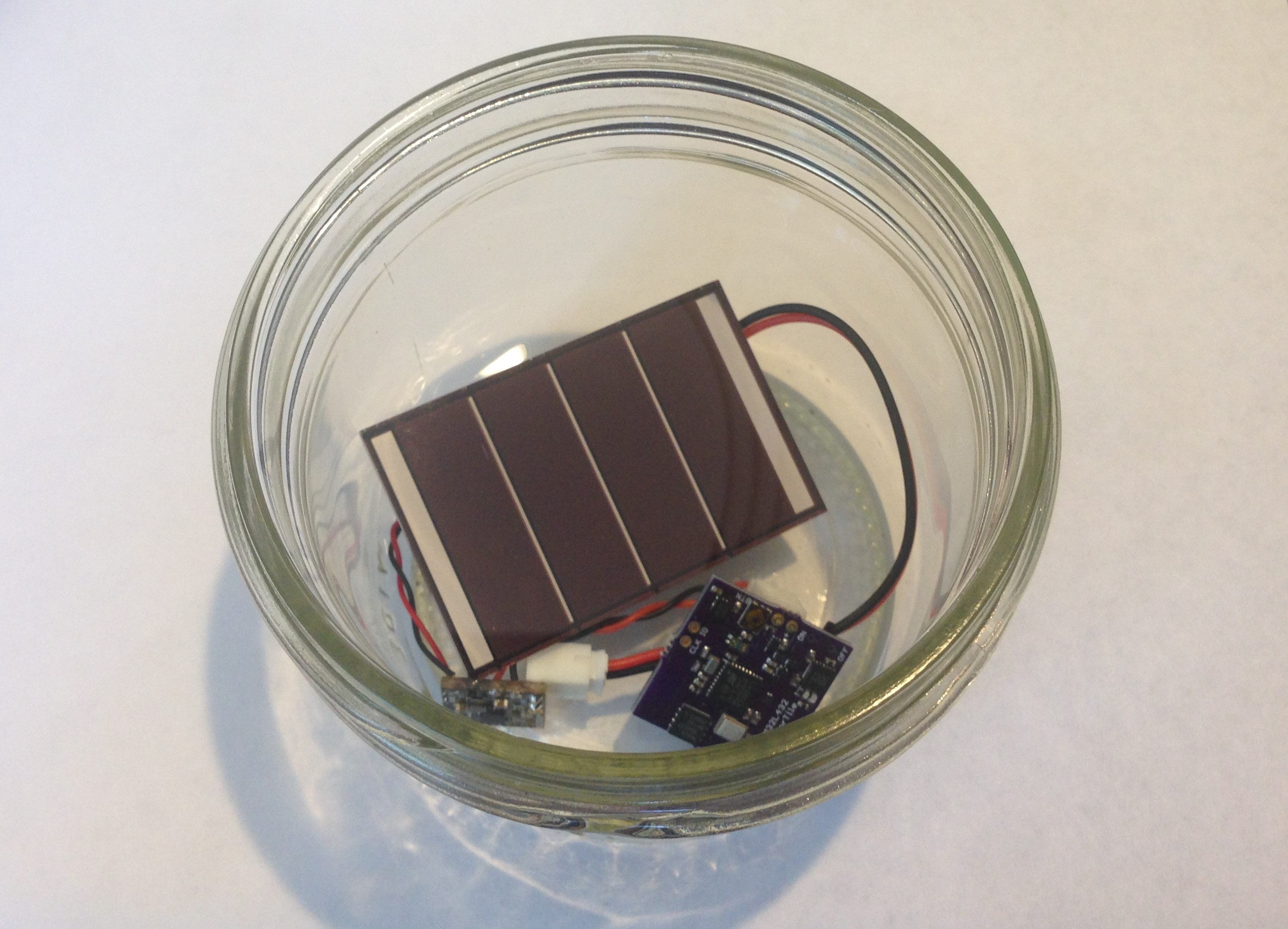
The BQ25504 is a high-efficiency boost converter of great flexibility that can be used to charge a battery using energy harvesting from a variety of sources. Here I have chosen to set the parameters of the boost converter to charge a standard one-cell, 4.2 V LiPo battery like this one. The BQ25504 employs a Maximum Power Point Tracking (MPPT) method which regulates the input impedance of the charger to maintain maximum efficiency of the solar cell. I have set the MPPT to 78% of the open-circuit voltage of the solar cell.

The BQ25504 protects the LiPo battery from undervoltage, which can cause damage through excessive discharge, as well as overvoltage to prevent excessive charging. The over- and under-voltage protection thresholds are set by a resistor network which I have chosen to limit discharging to 3.27 V and over charging to 4.27 V.
There is a battery OK threshold of 3.58 V and a battery hysteresis threshold of 3.78 V. The battery OK pin will toggle to LOW when the battery voltage falls below 3.58 V. The battery OK pin will toggle to HIGH when the battery voltage rises above 3.78 V. In other words, on decreasing battery voltage (due to discharging) the interrupt will fall and stay LOW (and the on-board green led will go out) below 3.58 V, and on increasing battery voltage (due to charging) the interrupt will rise and stay HIGH (and the green led will remain on) above 3.78 V. The battery OK pin allows an MCU to monitor the state of the battery charge. The idea is that the MCU can detect when the battery OK pin falls to the LOW logical condition (a sort of interrupt) and limit large loads until the solar cell is able to recharge the battery to a sufficient level to support the large current draw.
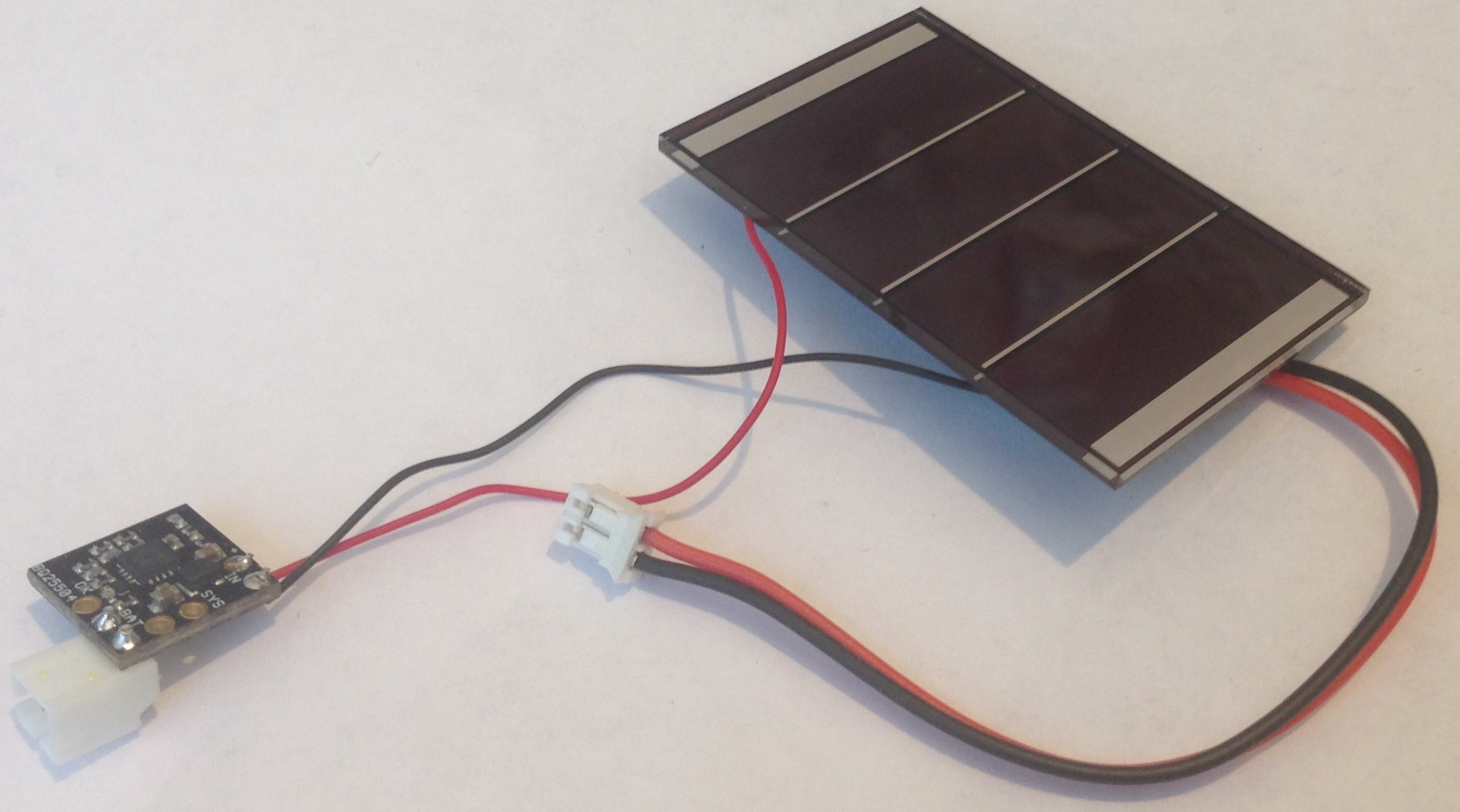
It sounds complicated, and it takes some time to get your arms around all of the detail in the data sheet, but it is really straightforward to use the BQ25504 in your applications. Connect the solar cell to the IN port, the LiPo battery to the BAT port. Use the OK pin as a battery charge detection interrupt and simply connect the SYS power (3.3 - 4.3 V!) and GND to the VIN/GND pins of your MCU.

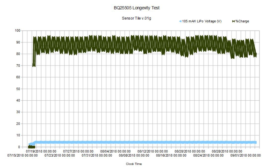
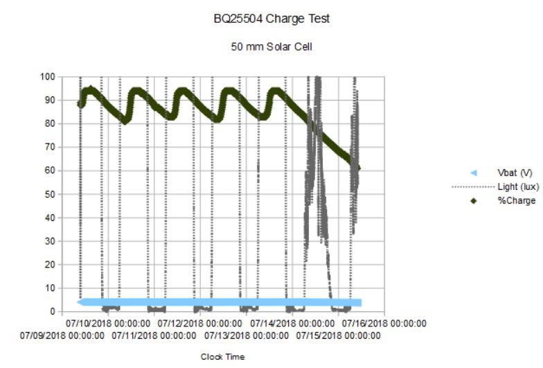
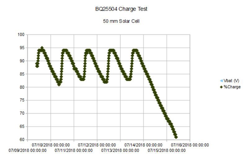
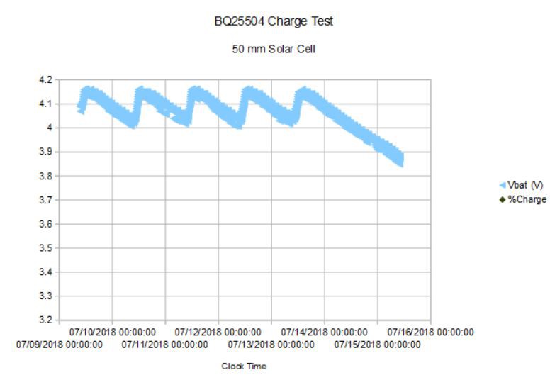
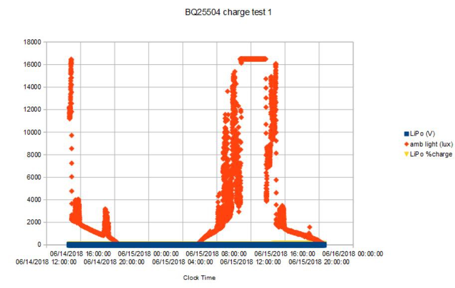
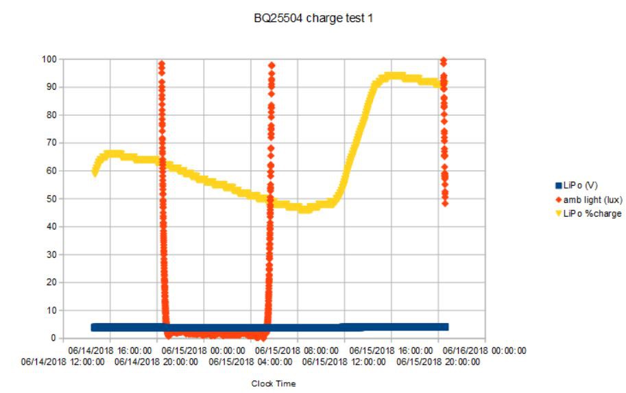
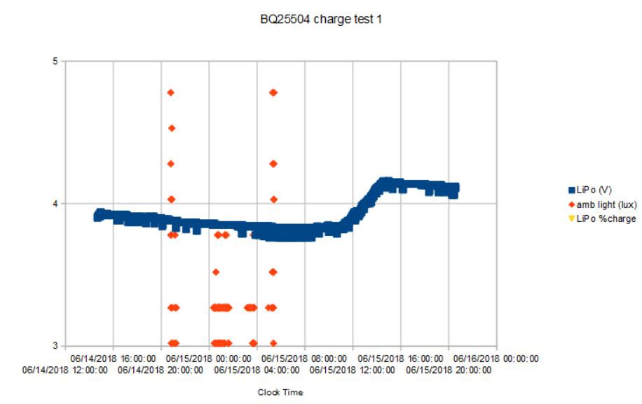
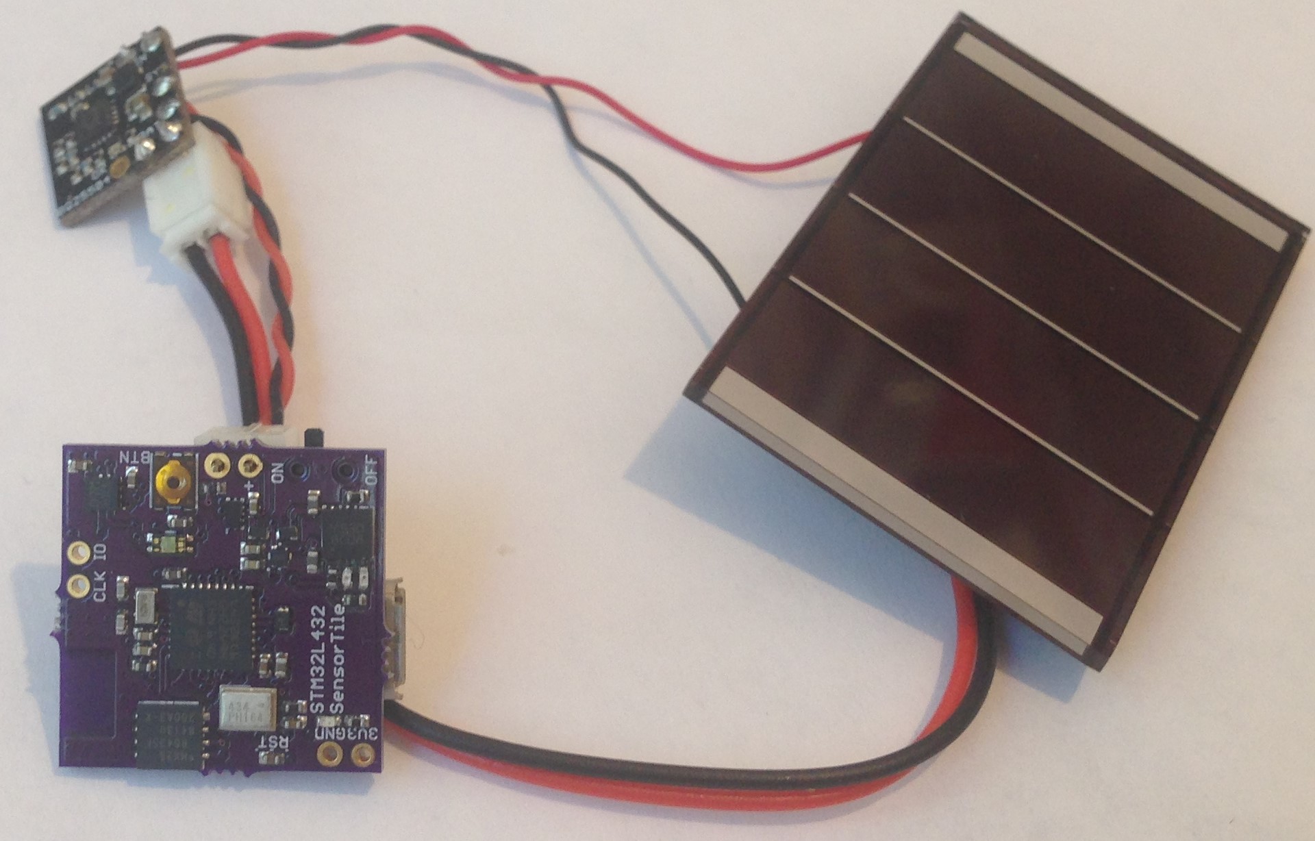
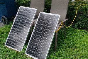
I have been using the BQ25504 along with this small 2.2V solar cell to power my SensorTile Environmental Data logging project. I have found that with 6 hours of direct sun (~20 klux) I am generating an average of ~7 mA per hour (at >90% efficiency!), just enough to keep the 1.8 mA Sensor Tile running indefinitely. You can read more about this and see plots of the charge versus time in the project logs.

Microsoft Excel - 11.00 kB - 06/04/2018 at 17:03

Download

solarcharger.v01b.zip

EAGLE design files

x-zip-compressed - 51.60 kB - 06/04/2018 at 17:02

Download

  • BQ25504 Longevity Test

    Kris Winer09/15/2018 at 22:01 0 comments

    09/15/2018

    I've been running the Sensor Tile v.01g (my workhorse for environmental data logging testing) powered by a 105 mAH 1S LiPo battery which is charged every day for about four hours by the BQ25504 solar charger connected to a small (30 x 50 mm) a-Si solar cell (see previous logs).


    The idea in the latest test was to just let the device run and see whether the BQ25504 can keep the LiPo battery charged for months while the Sensor Tile collects data (pressure, temperature, humidity, air quality, etc) every minute and stores the data to the onboard SPI NOR flash. In other words, can one really use the BQ25504 for long-term environmental data sensing/logging?

    And here is the answer:

    The experiment started on July 16. For the first day the data seems to be corrupted for some reason. Maybe I forgot to erase the SPI flash when I was testing the Sensor Tile prior to deploying it, I don't know. Anyway, on July 17 the charge state of the LiPo battery starts at ~70% and from then on remains in a band between ~75% and ~95% depending on whether the sun just "rises" (starts shining) on the solar cell (~75%) or the sun has just "set" on the solar cell (~95%).

    The data in the plot end on September 4, the actual data continue until September 5 at 19:48 when the SensorTile stopped as the humidity reached 99.9%. The device was exposed to the elements in a glass jar and the solar cell got a little dusty but all of the connections look fine, although the insulation on the wires is a little sun faded. But I have seen this kind of behavior before, when the BME280 humidity sensor gets saturated at 100% the SensorTile shuts down, probably due to a short in the BME280. So, the solution to this problem is using a proper container (see last log).

    I will simply claim that barring this humidity problem, the SensorTile would have continued to function essentially powered by the sun as long as the sun covered the solar cell for a few hours per day.

  • BQ25504 Working Like It Should

    Kris Winer07/15/2018 at 18:22 0 comments

    15 July 2018

    First a word about packaging. I designed the BQ25504 breakout board to be as small as possible because I had in mind the idea that it would become part of an integrated (hybrid) power source. That is, the LiPo battery, solar cell, and BQ25504 would be combined into a single integrated (and compact) "super battery" that would just plug into my environmental data logging devices.

    I even stuck the battery onto the back of the solar cell with foam tape and could do the same with the BQ25504, using foam tape to attach the BQ25504 board to the battery, for example.

    But this turns out not to be a very practical idea really, since it is always better to have a sensible container for the electronics and the solar cell is best mounted on the outside for sun exposure with the electronics protected somewhat from moisture, etc.

    So this is the container I created out of a $1 Bud box; the hole is to allow the VEML6040 ambient light sensor to monitor the light intensity, and to allow some air in for the BME280 pressure, temperature, and humidity sensor. And the only problem with this is that when it rains the electronics get wet and stop working. So I found some air permeable but water impermeable patches from Porex that at least let the pressure and humidity sensors work while keeping the inside of the container dry. I would have to use a transparent window for the light measurements. I will discuss this further on the SensorTile project page since this Ultra-Low-Power LiPo Charger project is supposed to be focused on the BQ25504 and its performance.

    And perform it does, just as expected once the system load is connected to Vbat as discussed in the last log. Here is the results of my latest test of a production BQ25504 breakout board:


    The experiment started at 9:30 AM on 7/9 just before local sunrise at the device (50-mm-wide solar cell, 105 mAH LiPo battery, BQ25504 breakout board and SensorTile.v01g). Fours hours of direct sun charged the LiPo battery from 89% (as determined by the on-board MAX17048 battery monitor) to a peak of 95% at 3 PM. Then the battery charge dropped to a minimum of 81% at 9 AM on 7/10 (vertical grid lines mark midnight). And the cycle repeats for five days until on 7/13 I removed the device from outside to my inside workstation where it was no longer exposed to direct sun.
    Here is a close up of the battery charge history:

    and the battery voltage history:

    If I had left the device undisturbed it would have remained running indefinitely (as long as there were four hours of sunlight per day), recording pressure, humidity, temperature, air quality, acceleration, RGBW light levels, battery charge and voltage, and time data every 10 seconds until the 8 MByte SPI flash filled up (probably another 20 days). Also sending out BLE reports of pressure, temperature, humidity, air quality and battery charge and voltage.

    The charge dropped from 94% to 61% in 43 hours after the device was removed from sun exposure, meaning the 105 mAH LiPo battery would have lasted a total of ~130 hours on a full charge, so an average current of 105 mAH/130 hours ~800 uA. This is a little less than I measured last time, but I also improved the sketch to minimize power further. Again, this is a proper subject for the SensorTile project.

    The BQ25504 plus solar cell makes for a practical power source for remotely-distributed environmental sensors and data loggers. Yes, one can always use a much larger battery. But for the smallest device implementation and/or to achieve ultra-long-term battery service, the BQ25504 clearly does the job.

  • Vstor is not Vsyst

    Kris Winer07/11/2018 at 00:58 2 comments

    I admit it!  When I designed the BQ25504 breakout board I didn't really understand everything in the data sheet.

    I missed the part about keeping the portion of the board with the resistor dividers free of GND pour (this is such a small board this "error" doesn't really seem to matter). I also used a single GND scheme; another violation of the reference design.  I didn't clean the resistor divider portion of the board with solvent after production as recommended (are you kidding me?).

    The biggest misunderstanding appears to be the role/purpose of Vstor, one of three BQ25504 outputs (Vbat and VbatOK the other two). I labeled this as Vsyst, since I assumed this was the output of the BQ25504 boost converter meant to power the microcontroller or whatever the combination solar cell charger/ LiPo battery was supposed to power.

    In fact, the data sheet says of VSTOR:

    "Connection for the output of the boost charger, which is typically connected to the system load."

    And I have been connecting the SensorTile power input to the Vstor/GND port of the BQ25504 in all of my testing to date. This works fine as long as the battery discharge from use of the SensorTile is the same or more than the battery charge during exposure to sunlight, as was the case last Summer when I was doing initial testing during cloudy or smoky days.

    What I have discovered this Summer with longer hours of direct sunlight, is that when the battery is fully charged (and the boost converter output exceeds the battery overvoltage threshold), Vsyst is turned off! This means the system load stops working, which is a bad thing (see previous log)!

    The solution is pretty simple. I removed the SensorTile input wire from Vstor and soldered the lead to Vbat. Now even if the battery full threshold is crossed and Vstor (formerly Vsyst) is shut off, the SensorTile itself will keep going and eventually the battery will run down sufficiently that the boost converter wll start up again when the sunlight returns, ad infinitum.

    So it seems the BQ25504 is supposed to have two power storage media, one connected to Vstor and one connected to Vbat. I am still a bit confused by this. What is the idea here, connect two batteries to the BQ25504, or connect a supercap to Vstor and a LiPo battery to Vbat?

    Right now I am in the middle of another SensorTile power test where I have connected a 105 mAH LiPo battery to Vbat/GND, connected the SensorTile input to Vbat also, and left Vstor unconnected.  This seems to work fine and I am now 34 hours into the test with the battery charge state oscillating between 84% (at 10 AM, local device "sunrise") and 94% (at 2 PM, local device "sunset").

    This is the current experiment: SensorTile, BQ25504, 105 mAH LiPo battery, and 50-mm-long solar cell in a glass jar on a cast-iron table out on my back deck where it enjoys ~4 hours of direct sun.

    I am keeping track of progress via BLE and I will report on the results in a few days (assuming the SensorTile doesn't conk out again!).

    Now, maybe the dozens of people who have bought and are using the BQ25504 SolarCell LiPo Battery Charger from Tindie for their own projects already know how to use it properly. It's embarrassing to say after a year of playing with this device that maybe I have just learned how it is supposed to work too!


    Now that I seem to have gotten the solar cell energy harvesting sorted out, I thought I would give Peltier junctions a try. The BQ25504 accepts energy inputs as low as 330 mV.

    Not knowing much about Peltier junctions (never stopped me before!) I selected the CP20151 made by CUI, Inc. Now these devices are intended to be powered in order to produce a temperature difference typically for localized cooling applications. And the data sheet specs quote the amount of temperature...

    Read more »

  • First Test of New Production Board

    Kris Winer06/16/2018 at 17:39 0 comments

    16 June 2018

    Well, first test because sometime last night (8.34 pm, to be exact) the Sensor Tile stopped working. I know this because that's the last entry in the SPI flash data log. I don't know why. The battery had nearly a full charge (91% at 4.11 V) at the time of stoppage so I assume it was a glitch or that the battery somehow became loose (the JST connector is just pressed into the JTS PTHs on the SensorTile, not soldered) or just one of those things. But this is somewhat rare in my testing to date, but usually I have the devices mounted in some kind of box, not a glass jar as in this case.


    Well, I got about 1.5 days worth of data, which is enough to tell that the BQ25504 boards with the new inductor are working well.

    First the record of the ambient light in lux measured from the VEML6040. I am using the smallest (40 ms) integration time since the sensor is in direct sunlight and the light pegs the sensor at its maximum output of 16384 lux for several hours per day. I estimate the incident sunlight is ~20 klux for at least four hours (x-axis grid spacing) a day. According to the data sheet, at 50 klux sun light the solar cell should be producing 16.9 mA at 2.2 V, so I am probably getting ~20 mA/50 mA x 16.9 mA ~7 mA per hour as I estimated in my previous experiments.


    The charge state of the 105 mAH 1S 3.7 V LiPo battery I used was about 60% at the start of the experiment, ramped up to ~68% with the one or two hours of sun left when I first placed the apparatus on the back deck table and then it fell through the night reaching a low of ~46%. I was able to query the battery voltage and charge level in real time using Adafruit's BLE UART app on my smart device, but nothing beats data recorded at ten second intervals on flash for later detailed analysis!

    The data capture a full day's worth of charging; even though the VEML6040 captured sunrise at ~5.45 AM on 6/15 (when the orange amb light line starts moving up, it is not until more or less direct sunlight falls on the solar cell at ~11 AM that charging really gets going. Peak charge is reached at ~4 PM, when the device enters the house shadow (local "sunset"), and then gradually falls until the device (and data recording) stops at 8:34 PM. Peak charge at 94% from minimum of 46% means about half of the battery capacity is added by the charger (roughly 50 mAH) per day. The device uses only ~68% - 46% ~ 22% of battery capacity per day so this set up should last indefinitely as long as there are a few hours of direct sun per day.

    The battery voltage responds as one would expect, reaching a minimum of 3.76 V at around 8 AM and peak battery voltage of 4.14 V at 4 PM 6/15.

    I will restart the experiment, maybe with the JST connector soldered to the SensorTile this time and see if I can get several days of data.

    Overall, I would say the BQ25504 Solar Cell LiPo charger works as advertised, at least with this particular solar cell. For some projects, 50 mAH per day of charging might not be enough, and the other variables including hours of sunlight, cloud cover, container, system device, etc will determine whether this solution will work for any given application.

    One thing I am curious about is whether this solution will work for some other method of power harvesting, not a solar cell but maybe thermoelectric or piezoelectric device. The only requirement is a DC voltage > 0.35 V. If I can find a suitable energy transducer, I will give this a try...

  • New Production Boards

    Kris Winer06/14/2018 at 18:38 0 comments

    14 June 2018

    It's always a gamble to have a large batch of boards produced in China. I have been working with a fab house in Beijing for a couple of years and I still get surprised by them. In this case, they couldn't source the specified inductor on the BQ25504 Solar Cell LiPo Battery charger so they went ahead and substituted with one that they thought was close. And without asking or telling me! I found out after receiving the 500 unit batch by inspection of the new boards:

    The new inductor seems to be slightly inferior to the old one:

    • the tolerance on the new part is +/- 20%, on the old part +/- 10 % lower is better
    • the DC resistance on the old part is 0.56 Ohm typical, 1.52 Ohm for the new part, lower is better.
    • saturation current of old part is 0.64 A, new part is 0.53 A, higher is better.

    Does any of this matter? I don't know. So I thought I would do a test of performance just to check.

    I pulled a random board out of the box and soldered it to a 50 mm x 33 mm, 2.2 V solar cell and LiPo battery connector:

    It looks like the green led is not working (I have found a few, maybe ~2% of the boards have this problem, just my luck) since I measured 4.15 V on the system and battery and battery OK outputs with this rig using light from my white led desk lamp. This is actually a blessing in disguise; while it is useful to have led indication to tell when the board is charging it does use up ~200 uA for little benefit. In use I would knock the led off of the board anyway to save this power. Still, it is in the design and is supposed to work.

    So the main charging function of the board seems to work just fine. But this isn't enough. I want to verify that the charger can generate enough power to run a useful device (or rather, measure the power generated in a typical use case).

    I would use my LoRaSensorTile as  test vehicle but the average power usage of this is 40 uA, or about 1 mA per day. Really not enough for a good power test! Instead I will go back to my STM32L4 SensorTile with the CCS811 which causes the average power usage to be more like ~1-2 mA. Then with ~6 hours of sun at ~7 mA power generated I should be able to keep this going indefinitely. I really just need to capture a few days worth of data to verify that the charger is working well.

    I'll connect the SensorTile and run the experiment over a week or so. The SensorTile has BLE so I can keep track of what it is doing in real time on the smart phone but the most useful analysis will come from the data captured and stored onto the SPI flash that I will look at in detail when the experiment is over.

    First check of function and all looks good:

    33.4 972.9 27.1 0 0 3.91 59.5
    33.6 972.9 26.5 0 0 3.91 59.5
    33.7 972.9 26.5 0 0 3.91 59.5
    34.0 972.8 26.1 0 0 3.91 59.5
    34.5 972.9 25.6 0 0 3.91 59.5
    34.6 972.8 25.5 0 0 3.91 59.5
    34.8 972.8 25.3 0 0 3.91 59.5
    35.0 972.8 24.9 0 0 3.91 59.5
    35.2 972.9 24.7 0 0 3.91 59.8
    35.4 972.9 24.5 400 0 3.91 59.8
    35.8 972.9 23.9 400 0 3.91 59.8
    35.8 972.9 23.5 400 0 3.91 59.8
    35.5 972.9 23.5 400 0 3.91 59.8
    35.4 972.9 24.2 400 0 3.91 59.8
    35.5 972.9 24.0 400 0 3.91 59.8
    35.6 973.0 24.1 400 0 3.91 59.8
    36.0 973.0 24.0 400 0 3.91 59.8
    36.2 972.9 23.8 400 0 3.91 59.8
    36.4 972.9 23.4 400 0 3.91 60.1
    36.7 972.8 23.0 400 0 3.91 60.1
    36.8 972.9 22.5 400 0 3.91 60.1
    37.0 972.8 22.6 400 0 3.91 60.1
    36.8 972.8 22.7 400 0 3.91 60.1
    36.5 972.8 22.6 400 0 3.92 60.1
    36.3 972.8 22.5 400 0 3.92 60.1
    36.3 972.8 22.8 400 0 3.92 60.1
    36.4 972.9 22.5 400 0 3.92 60.1


     This is the output from my smartphone showing temperature in C, pressure in mbar, humidity in %rH, the eCO2 in ppm and the TVOC in ppb (from the CCS811), the battery voltage and battery % full charge (from the MAX17048 fuel gauge). I placed the device in the remnants of the sun on the table on the back deck so I am pleasantly surprised to see all of the sensors reporting sensible values...

    Read more »

View all 5 project logs

Enjoy this project?

Share

Discussions

Szymon Slupik wrote 01/24/2020 at 14:34 point

HI, regarding:

"What I have discovered this Summer with longer hours of direct sunlight, is that when the battery is fully charged (and the boost converter output exceeds the battery overvoltage threshold), Vsyst is turned off! This means the system load stops working, which is a bad thing (see previous log)!"

I'm using the Tindie modules and they do not cut the power to the load, When the battery is charged, a small green LED turns on and the load continues to be powered.

  Are you sure? yes | no

Antoine wrote 10/16/2018 at 16:28 point

Hi Kris,

You mention a POREX® patch. May you tell me what material (Ref/Dim) you  purchased ?

Greetings.

Antoine

  Are you sure? yes | no

Kris Winer wrote 10/16/2018 at 16:31 point

I received samples from the company, both patches and "cloth" that are air permeable but water impermeable. If you contact them, they might also send you free samples. But the cost of their products is very reasonable.

  Are you sure? yes | no

Kris Winer wrote 07/08/2018 at 21:15 point

Thanks for the head up---I'll take a look. One thing I don't like about the BQ25504 is that it is rather complicated to design with. It works great, and is very flexible, but the flexibility comes with a cost in working out a suitable design. 

  Are you sure? yes | no

Daniel wrote 07/08/2018 at 21:10 point

Very nice :)
I saw similar IC from ST - SPV1040 and SPV1050. The SPV1040 have even MPPT perturb and observe algorithm.

  Are you sure? yes | no

Similar Projects

Does this project spark your interest?

Become a member to follow this project and never miss any updates