0%
0%
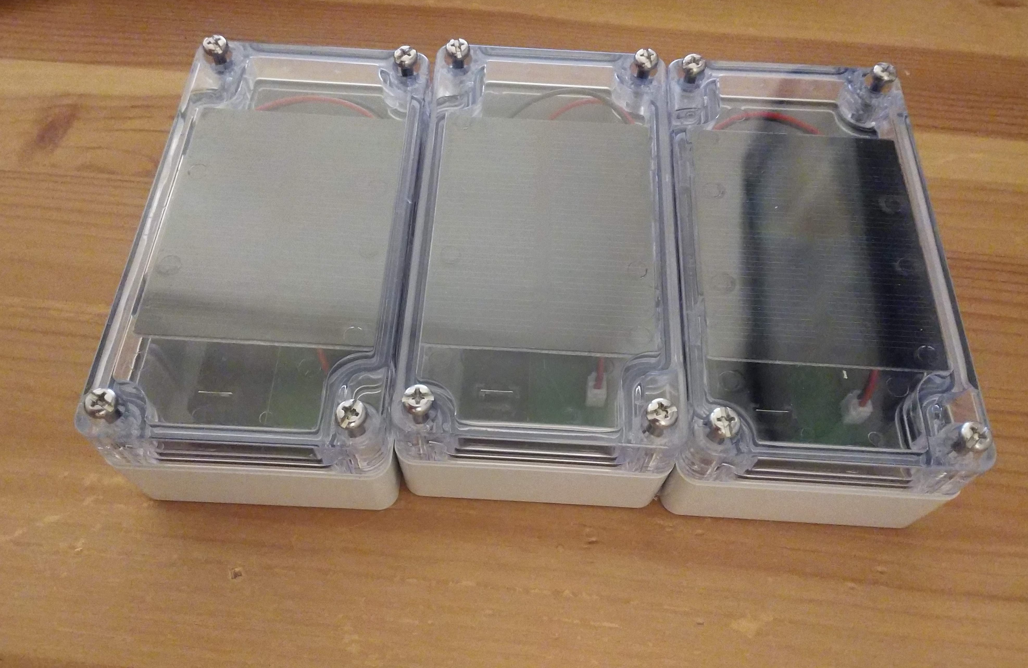
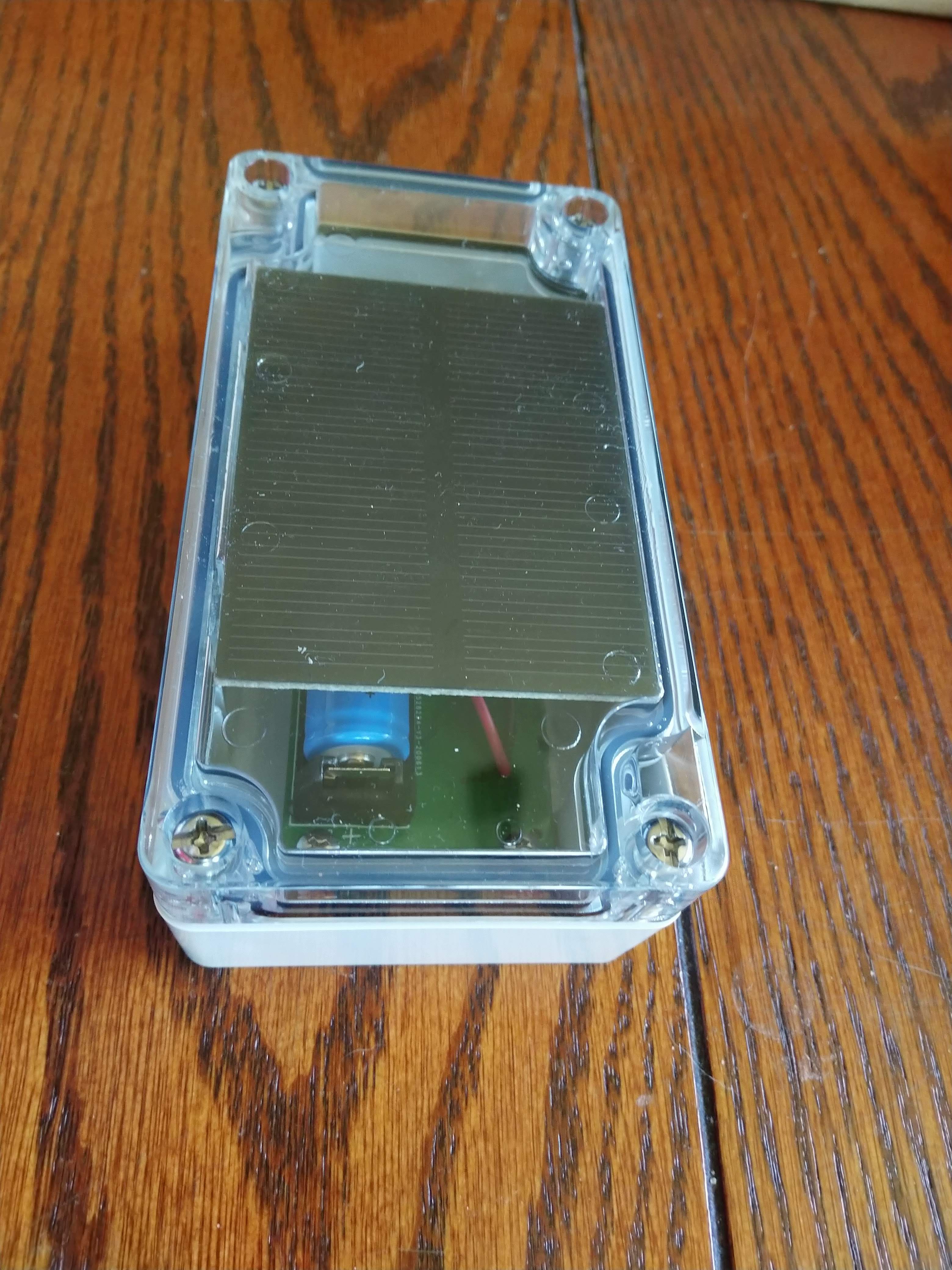
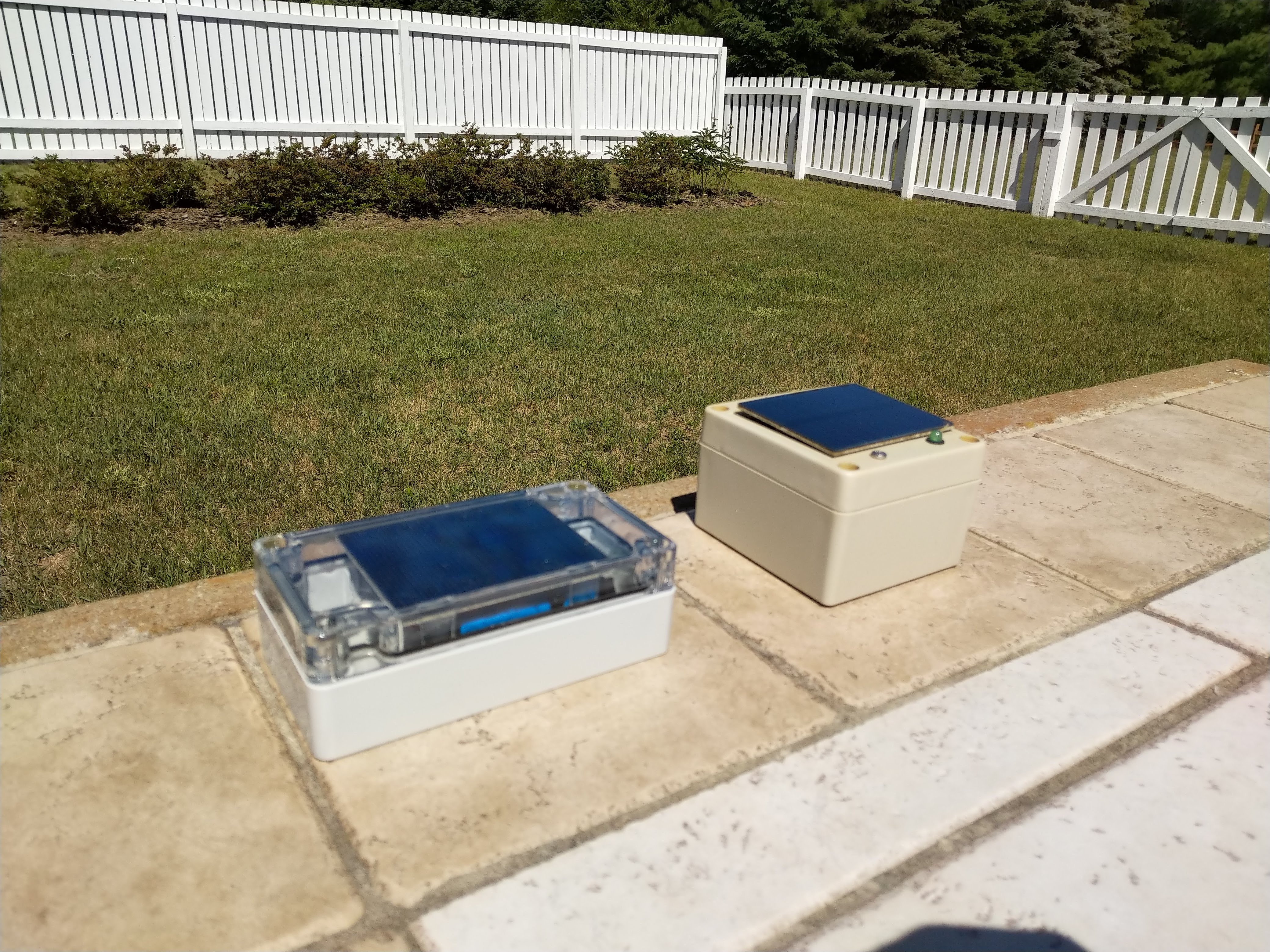
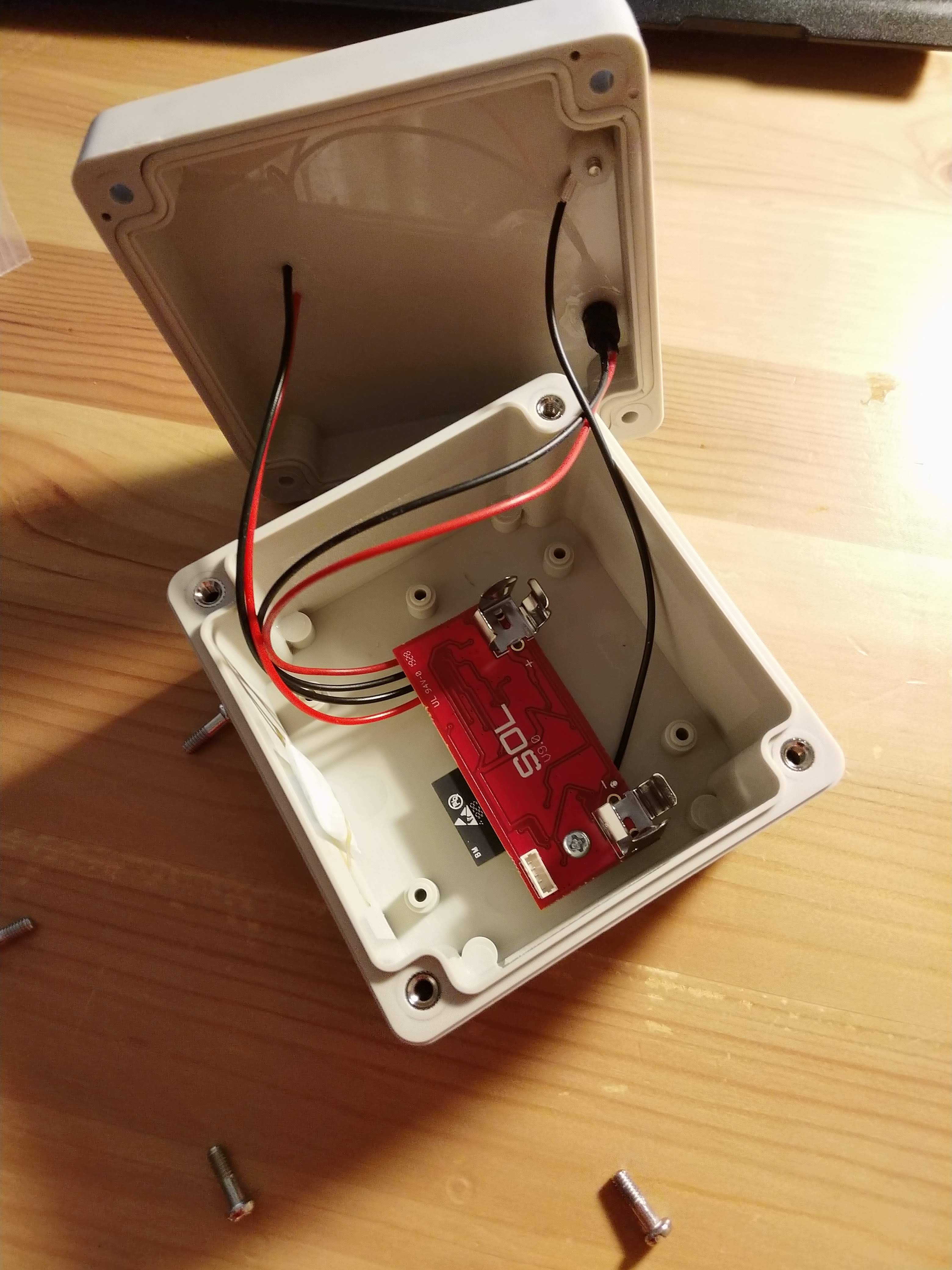
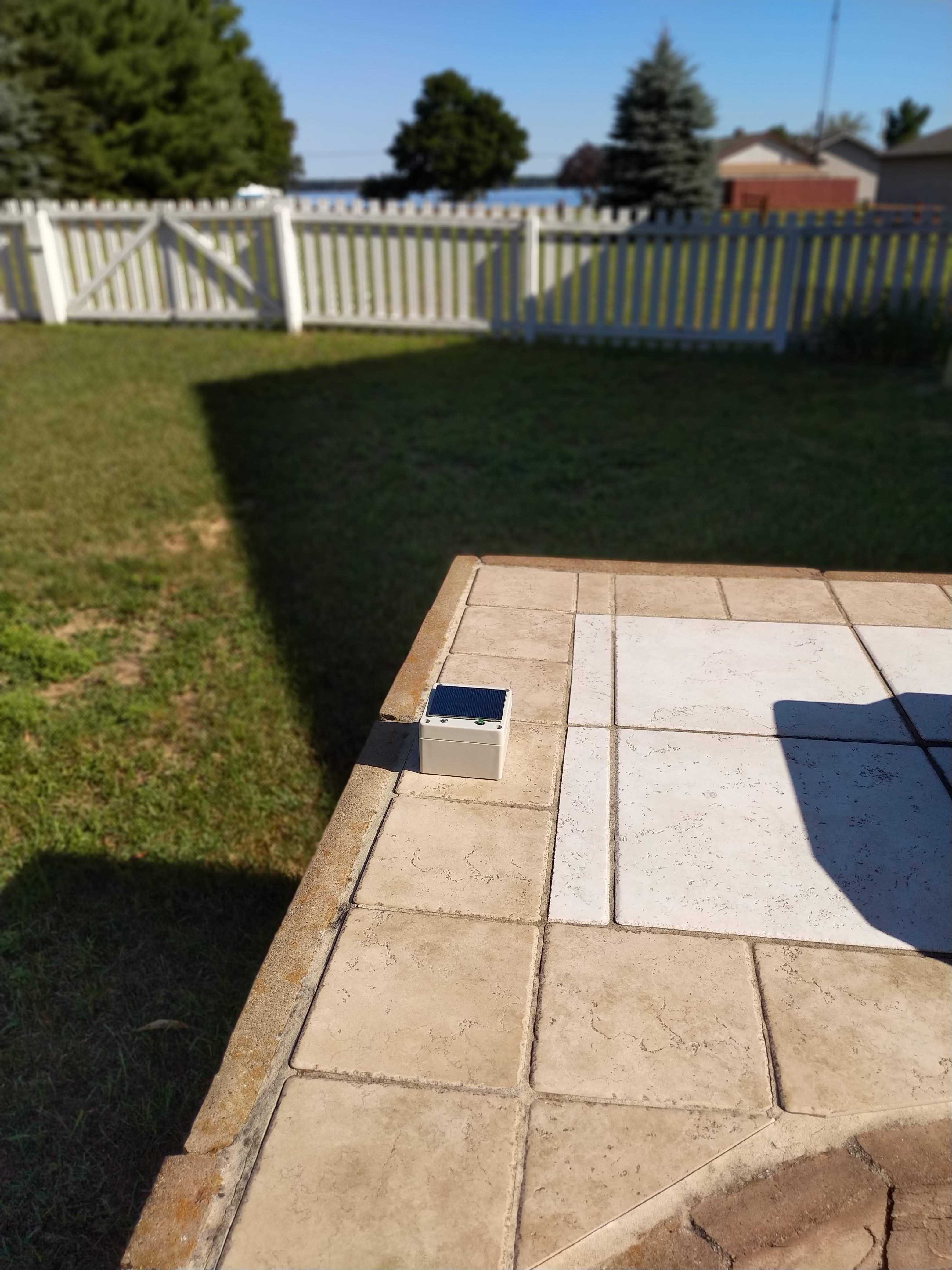
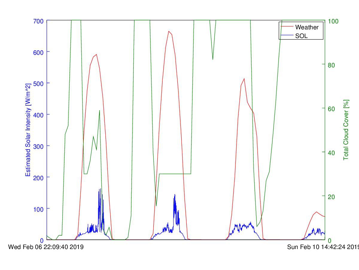
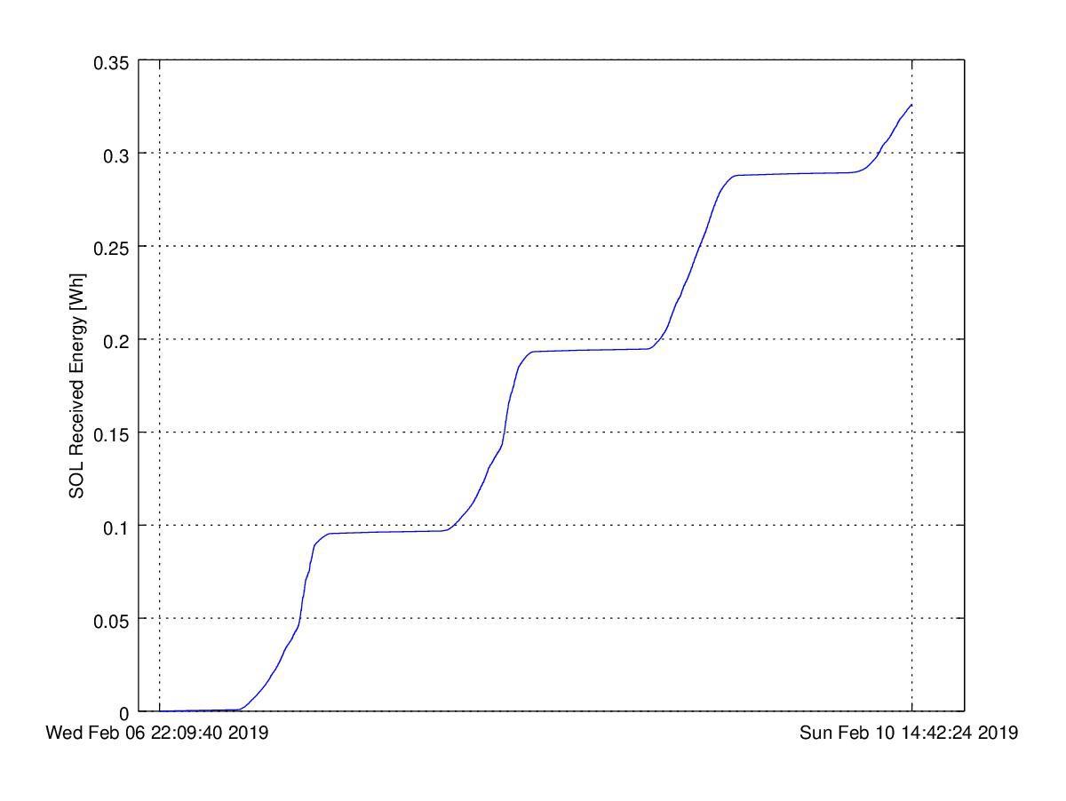
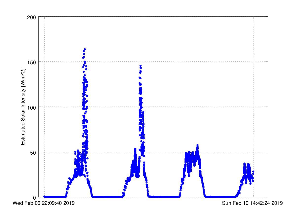
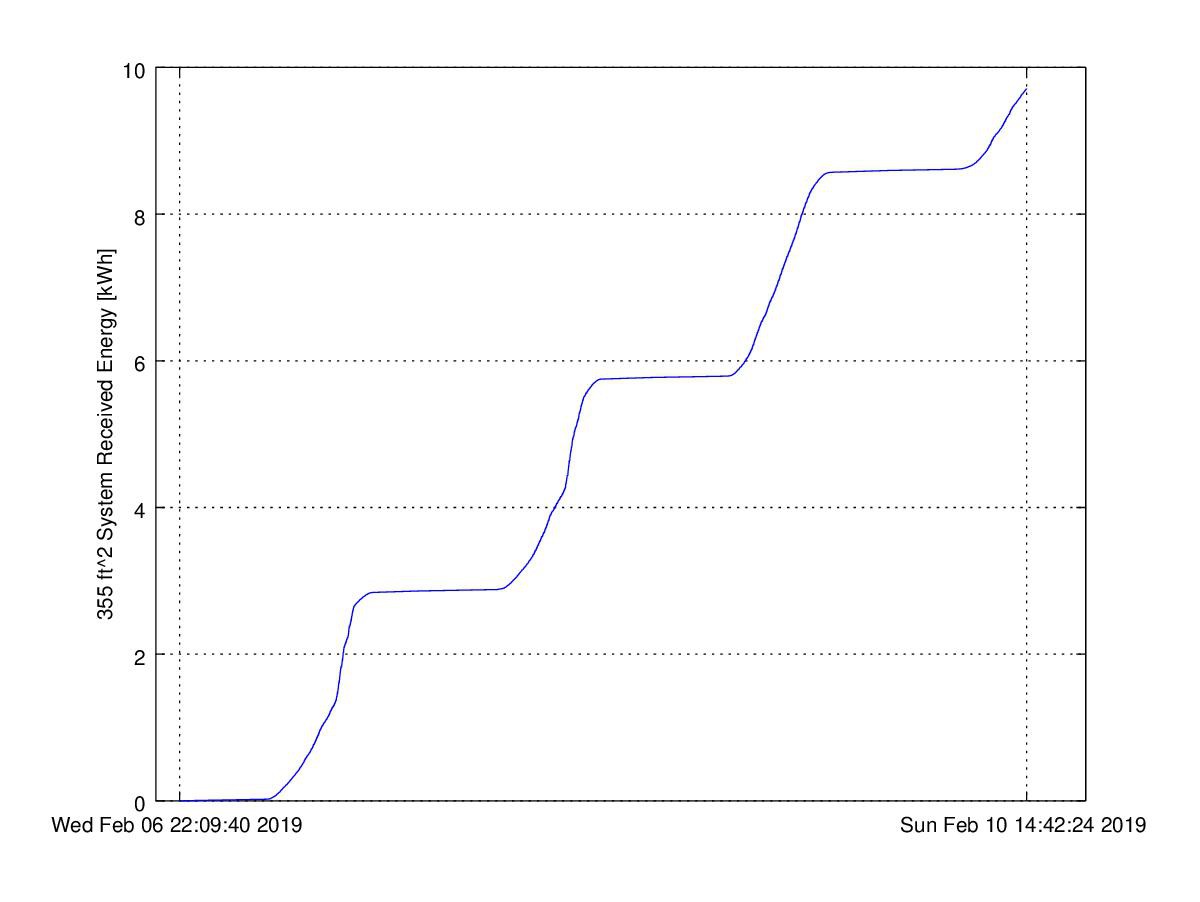
SOL: Long-term solar intensity sensing
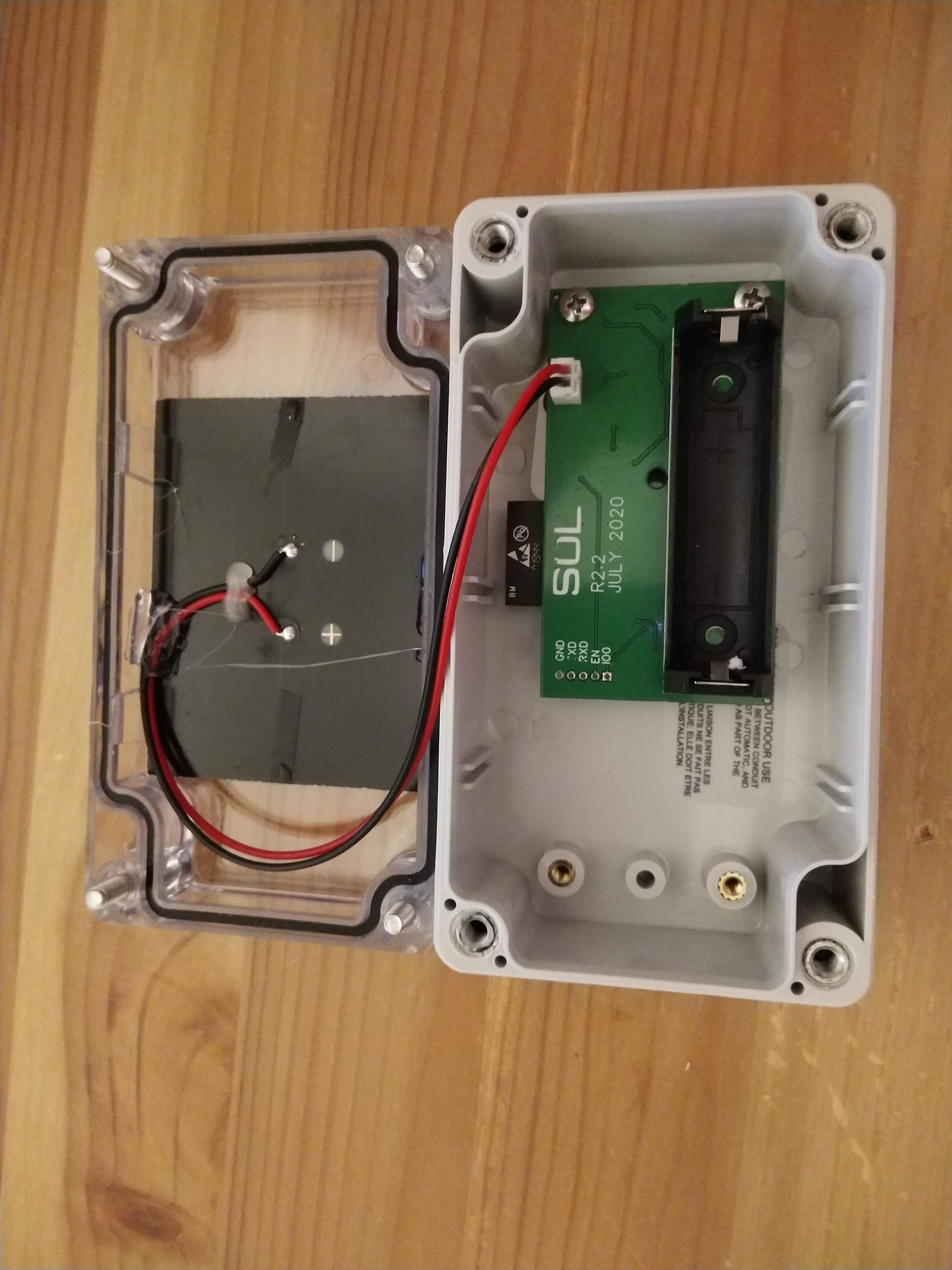
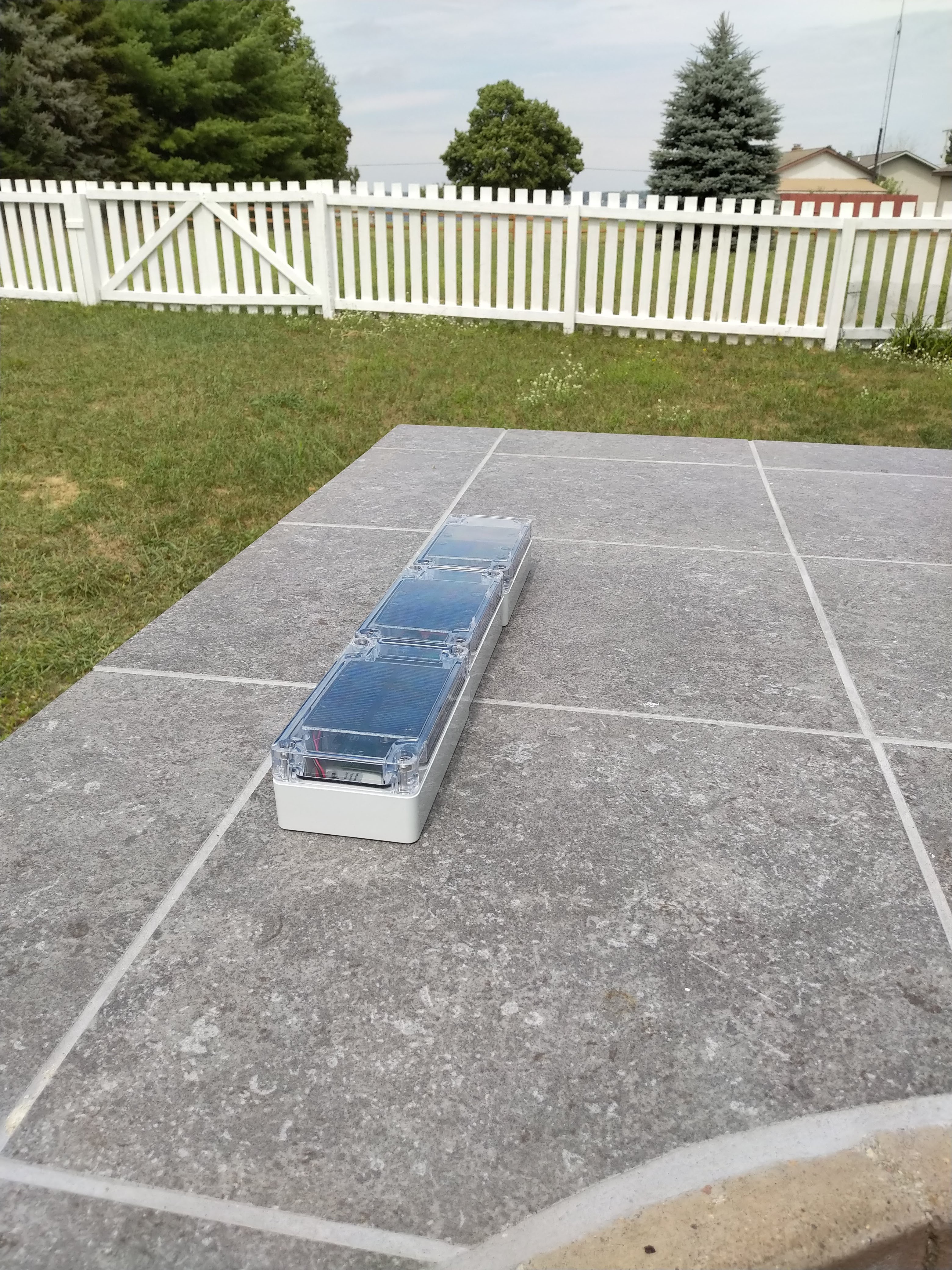
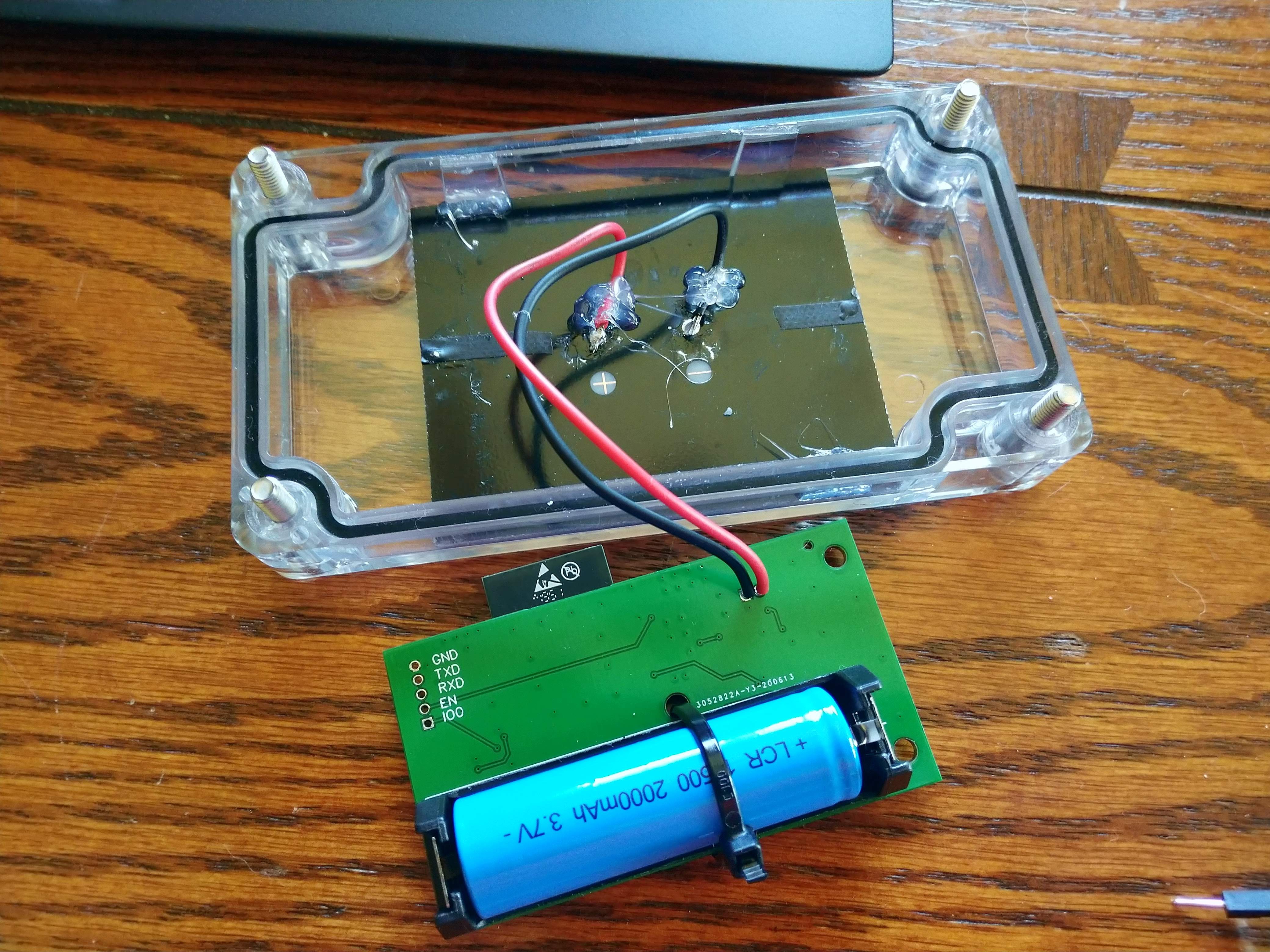
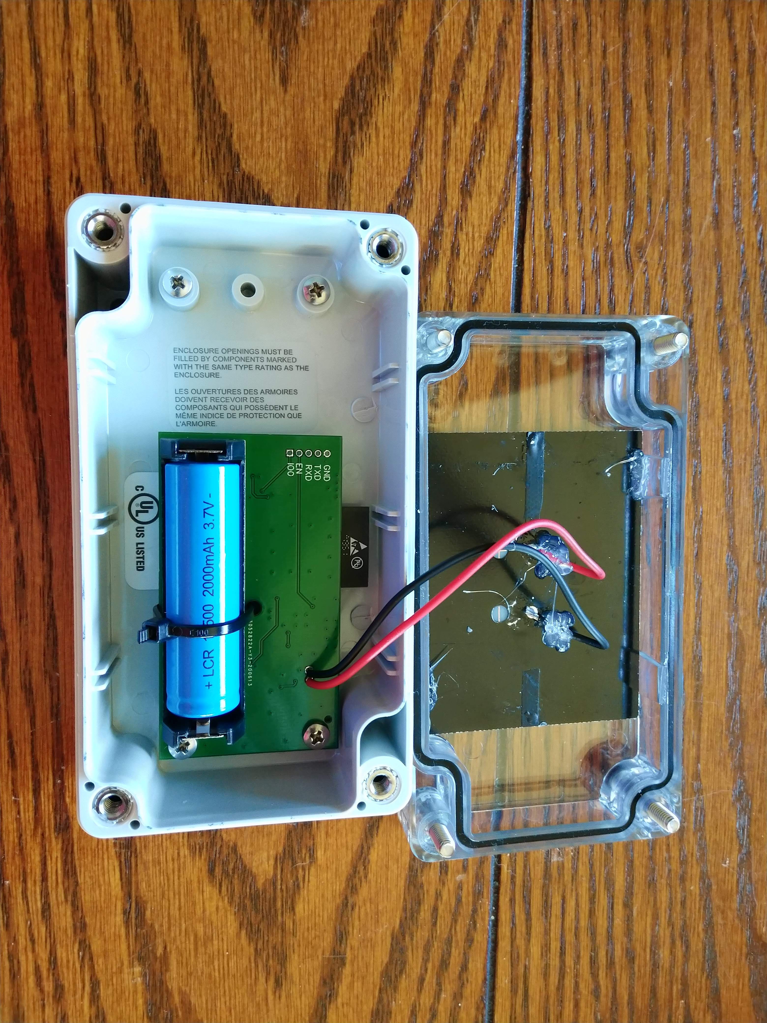
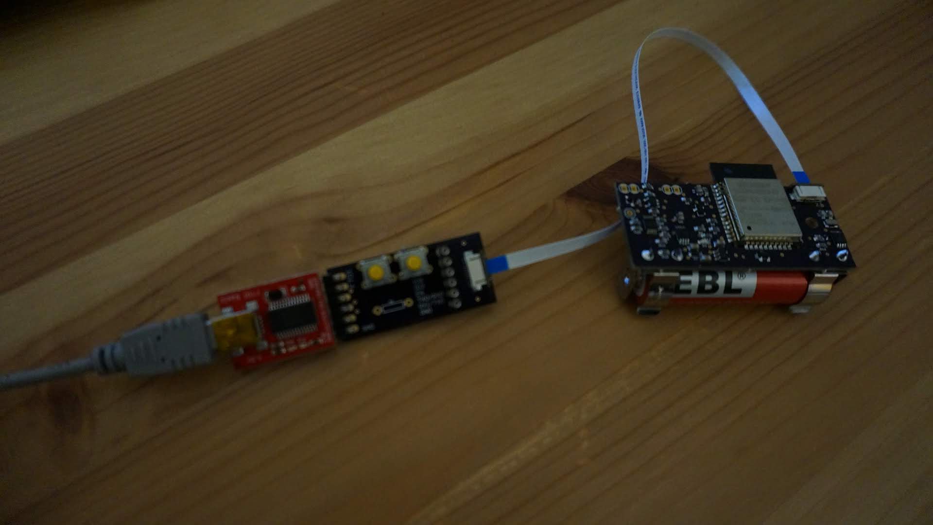
SOL is a project to develop a solar powered, connected solar intensity sensor (also known as a pyranometer)
Become a Hackaday.io member
Already have an account? Log in.
Just one more thing
To make the experience fit your profile, pick a username and tell us what interests you.
Pick an awesome username
hackaday.io/
Your profile's URL: hackaday.io/username. Max 25 alphanumeric characters.
Pick a few interests
Projects that share your interests
People that share your interests


 mihai.cuciuc
 Victor
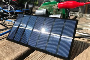
 Brian Sutherland
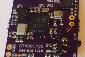
 Kris Winer
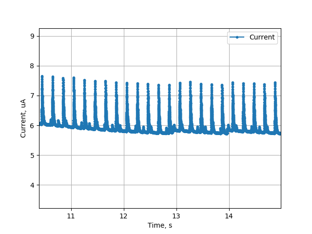
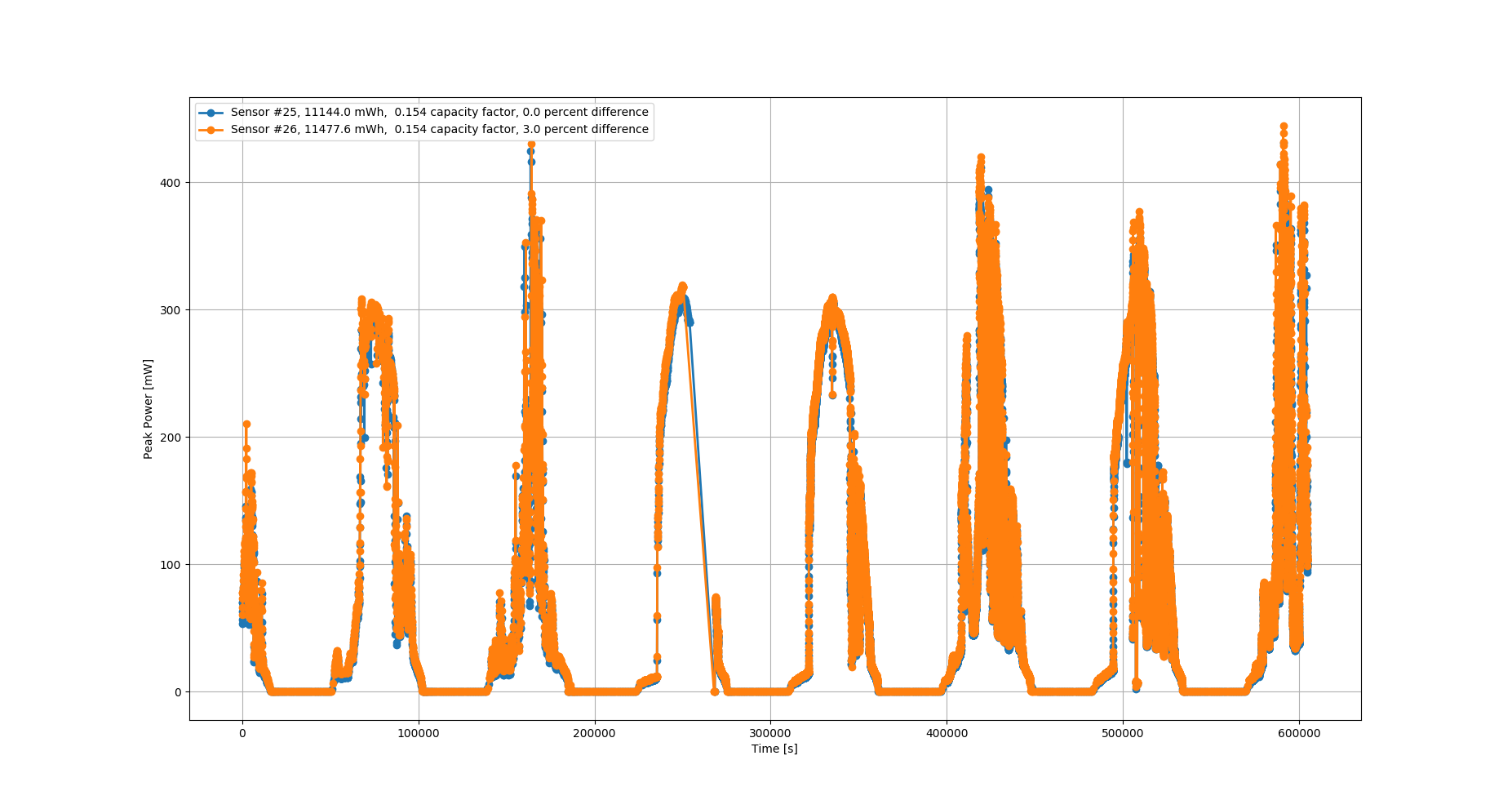
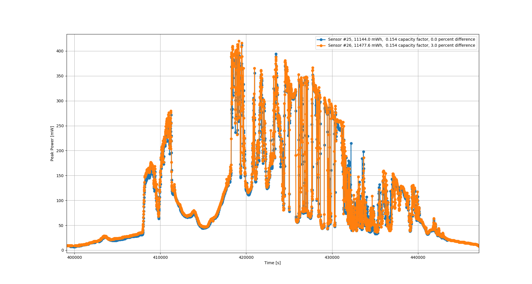
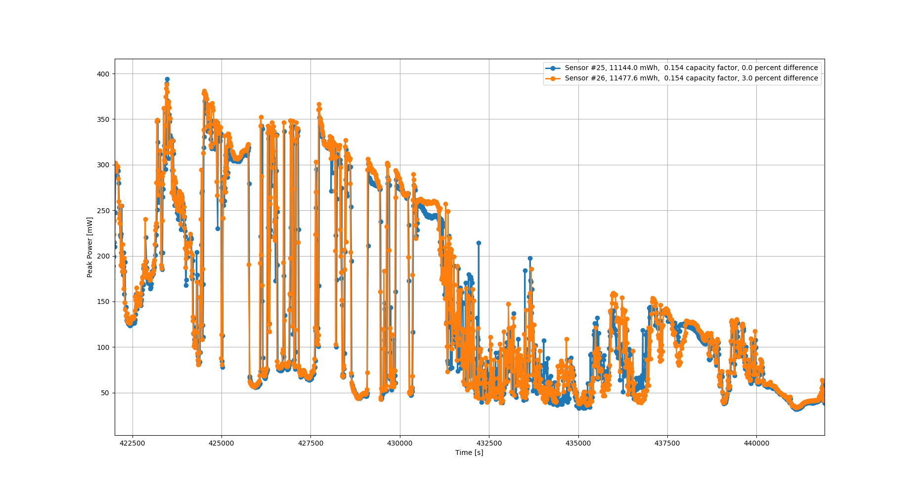
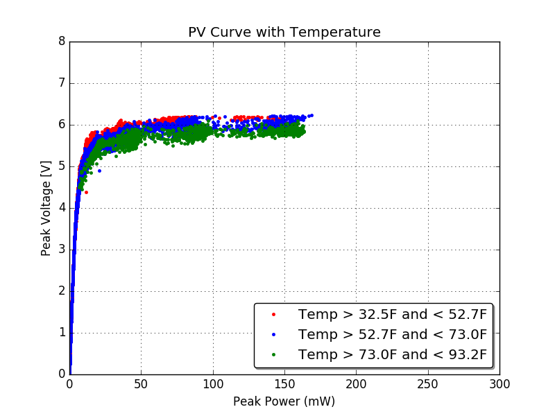
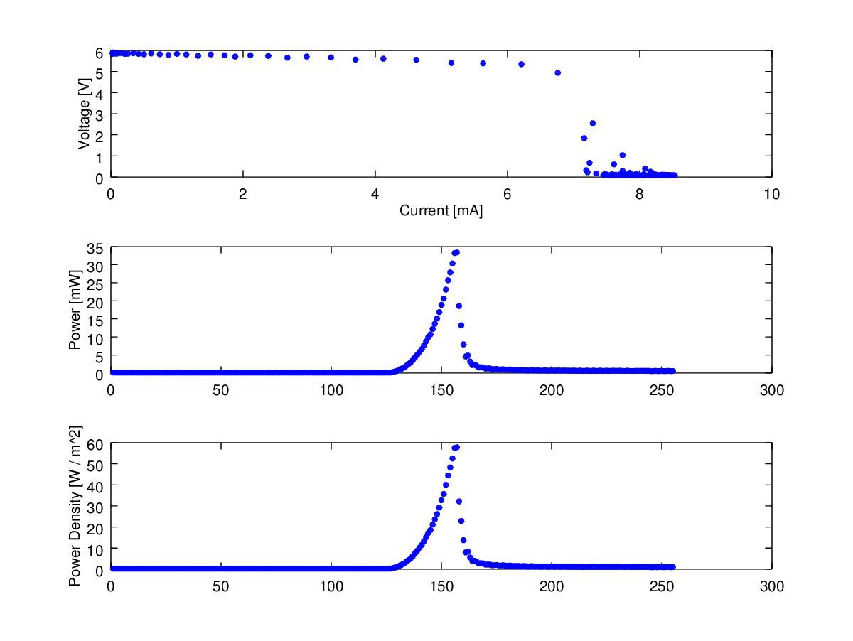
@Jake Wachlin I was intrigued to see you using the DAC sweep on your MOSFET gate to explore the power curve of your pv cell. Do you have a reference where you saw this done elsewhere or would you mind giving more detail if you thought of it independently? I always considered it "bad form" to run a FET gate below "VgsThres * 2-ish" but you're taking advantage of it. Did you need to map carefully from datasheet plots or is it just a case of gathering enough V and I measurements across the DAC range to calculate the MPP?