 muzi
muziIntroduction
In this ESP32 tutorial, we will check how to get measurements from a C02 sensor, using the Arduino core.
The sensor used was an Analog Infrared CO2 Sensor from DFRobot. You can find the Wiki page for the sensor here.
Note that the code we are going to be developing here is based on the code available on the Wiki page of the product, which I encourage you to check.
The tests were performed using a DFRobot’s ESP32 module integrated in a ESP32 development board.
About the sensor
The Analog Infrared CO2 sensor allows to measure the CO2 air concentration in a range from 0 to 5000 ppm (parts per million), with an accuracy of ± 50ppm + 3% of the reading [1]. The sensor operation is based on the NDIR technology (nondispersive infrared) and includes temperature compensation.
This sensor can operate with a voltage supply in the range of 4.5 V and 5.5 V and outputs an analog signal between 0 V and 2 V [1].
If the analog voltage corresponds to 0 V, it means that an error was detected during the self checking procedure. Between 0 V and 0.4 V, it doesn’t represent any measurement and the values on this range are outputted during the pre-heating phase of the sensor, which has a duration of 3 minutes.
During normal operation, the sensor outputs a voltage between 0.4 V and 2 V, which corresponds to concentrations of C02 of 0 ppm and 5000 ppm, respectively. As can be seen in the product Wiki, there is a linear relation between the voltages in that range and the CO2 concentration, so we can obtain the concentration from the voltage using a simple proportion.
Electronic schematic
Since this is a ready to use module, the electronics needed for this tutorial are very simple. As illustrated in figure 1, we just need to power the device with 5 V and connect its data pin to a pin of the ESP32 that can read analog voltages.
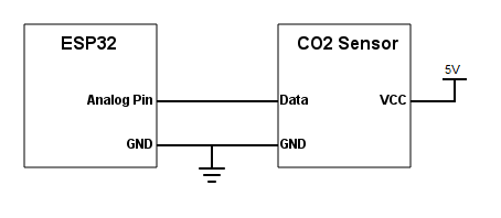
Figure 1 – Electronic schematic.
Note that the sensor doesn’t have any labels on the pins, so we need to perform the connections taking into account the colors of the wires that come with it. Following the usual color scheme, the black wire corresponds to GND and the red to VCC. The blue wire corresponds to the data signal.
Depending on your ESP32 board, it may be able to provide the power supply needed for the sensor from a power pin. Nonetheless, if you are not sure if it has such pin or if it can provide enough current to the sensor, the best approach is to use an external power supply such as this.
ESP32 Analog readings
As analyzed in the previous sections, the sensor outputs an analog voltage that the ESP32 will need to read. Since we are using the Arduino core, the easiest way of reading an analog voltage is by using the analogRead function, which is also implemented for the ESP32, as we can see here.
Nonetheless, at the time of writing, the analogRead function is returning inconsistent values on the ESP32, as can be seen by this issue. As discusses in this forum thread, this is most likely caused by the non linearity on the ADC (analog to digital converter) values.
You can check at the IDF documentation more information about this and some calibration methods that can be used.
Since these are more complex procedures that are outside the scope of this post, we will assume the linearity of the analog readings on the 0 V to 3.3 V range. Naturally, this will introduce some imprecision on out measurements, but the main focus of the tutorial is how to interact with the sensor rather than how to solve these non-linearity issues.
Since the ESP32 integrates two 12 bits ADCs [2], it means that we can obtain digital values between 0 and 4095 (212 – 1) for the analog voltage measurements. Note that we...
Read more »
 numero_trey
 Marcrbarker
 ivoras
 Florian Wilhelm Dirnberger