 Andrew
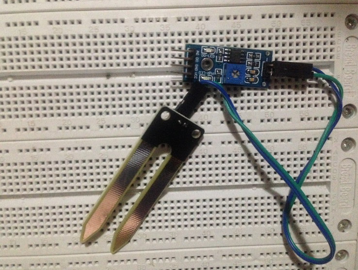
There are total four pins Soil moisture sensor (you can redeem it free from PCBWay) :
VCC pin: power supply positive
GND pin: power negative
A0 pin: Output the analog voltage value of soil moisture sensor, range from 0 to 1023
D0 pin: Output the switch value of soil moisture sensor, 0 and 1,
Use a simple code to test, check the output value of the A0 pin, the program as follows:
const int buttonPin = A0;
int inputValue = 0;
void setup() {
pinMode(buttonPin, INPUT);
digitalWrite(buttonPin,LOW);
Serial.begin(9600);
}
void loop() {
inputValue = analogRead(buttonPin);
Serial.println(inputValue);
}
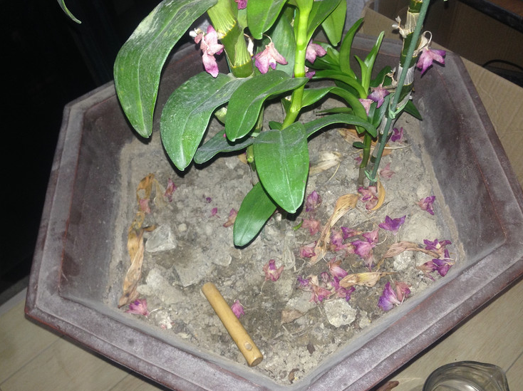
There is a large flowerpot in my home. I put the soil moisture sensor in the flowerpot to test. The picture of the flowerpot as follows. The soil moisture sensor will insert in different positions during the test.
Finally collected more than 8000 data, put these data into matlab, get the following graph:
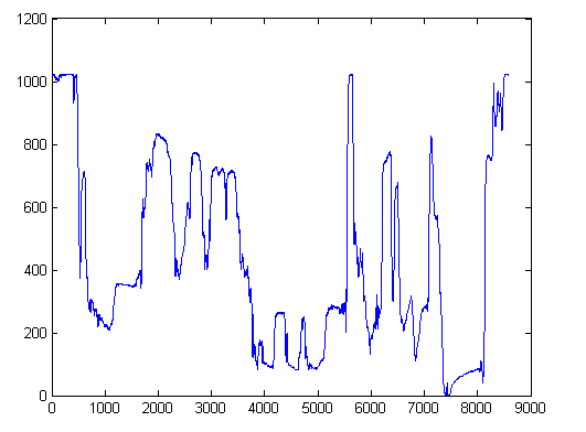
The output of A0 pin is 1023 when the soil moisture sensor didn’t insert into flower pot..
When the soil moisture sensor inserted into a certain position of the flower pot, the output value of the A0 pin rapidly drops to a certain stable value. Then pull out the soil moisture sensor, and insert it into other positions of the flower pot. At this time, the A0 pin outputs different analog values depend on the humidity in different positions.
 Arduino KIT
 jlbrian7
 Hulk
Hulk
Is there room to add easily more data points (sensors) from a general standpoint without affecting the current specifications like battery life. I started a similar concept using Amazon Sidewalk sensor with the intention of adding and expanding Wi-Fi limitations, like a greenhouse and used on a semi mass scale designed for commercial growth operations. For example the the legal medical cannabis industry. I’d love to learn more about your project and pick your brain.