0%
0%
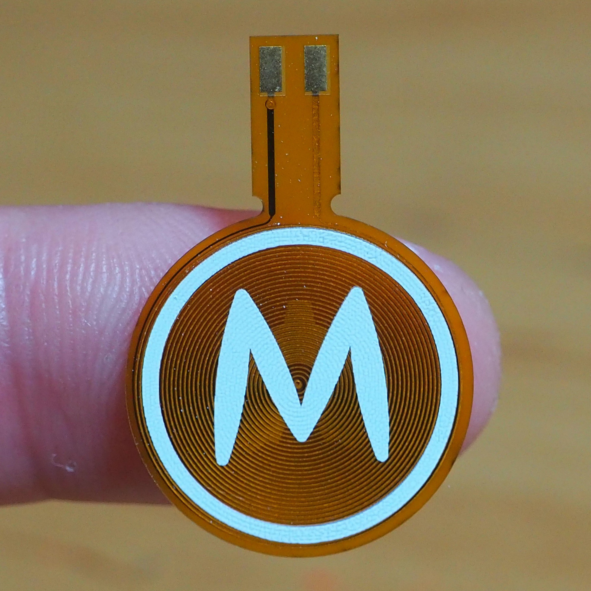
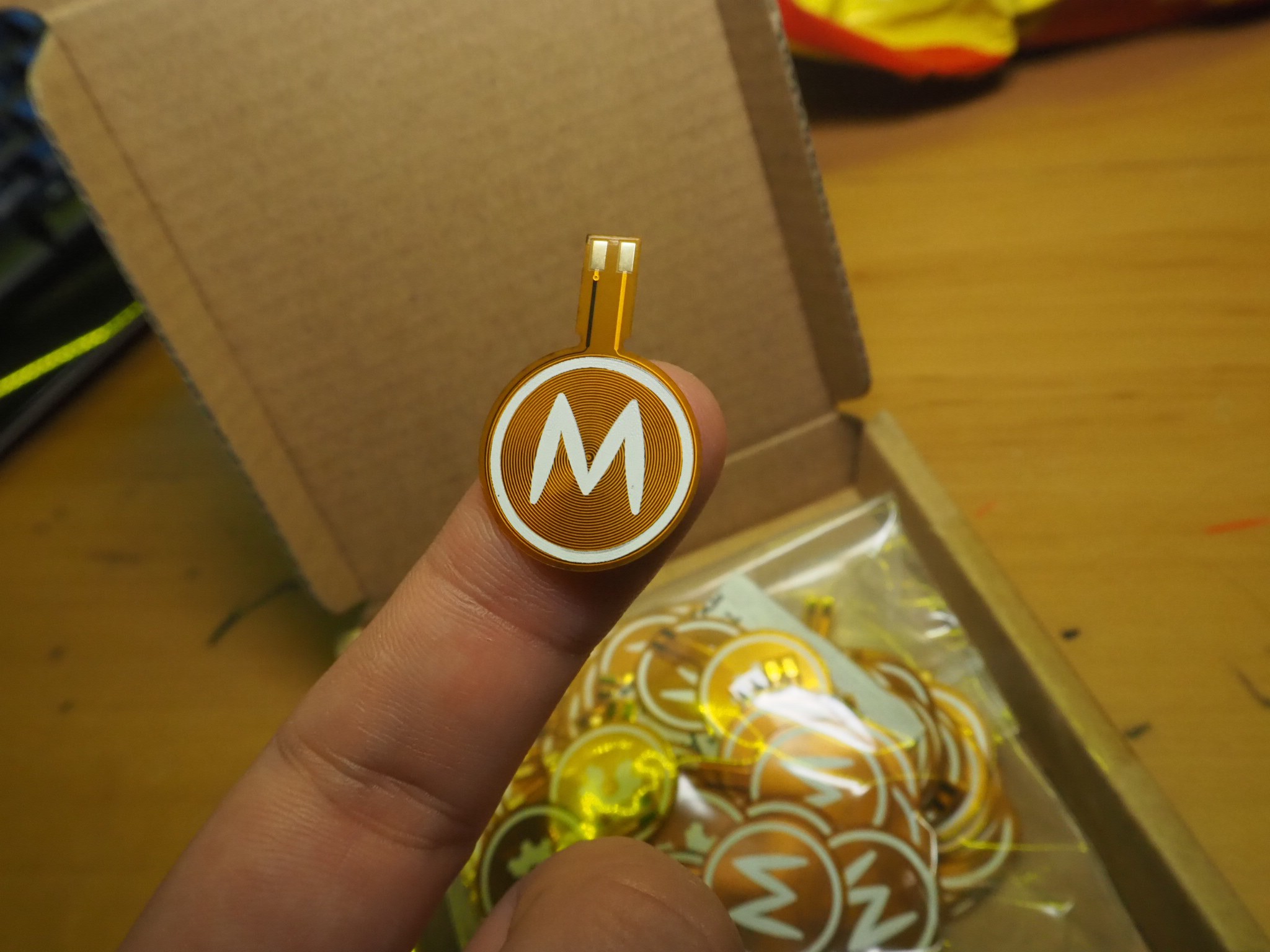
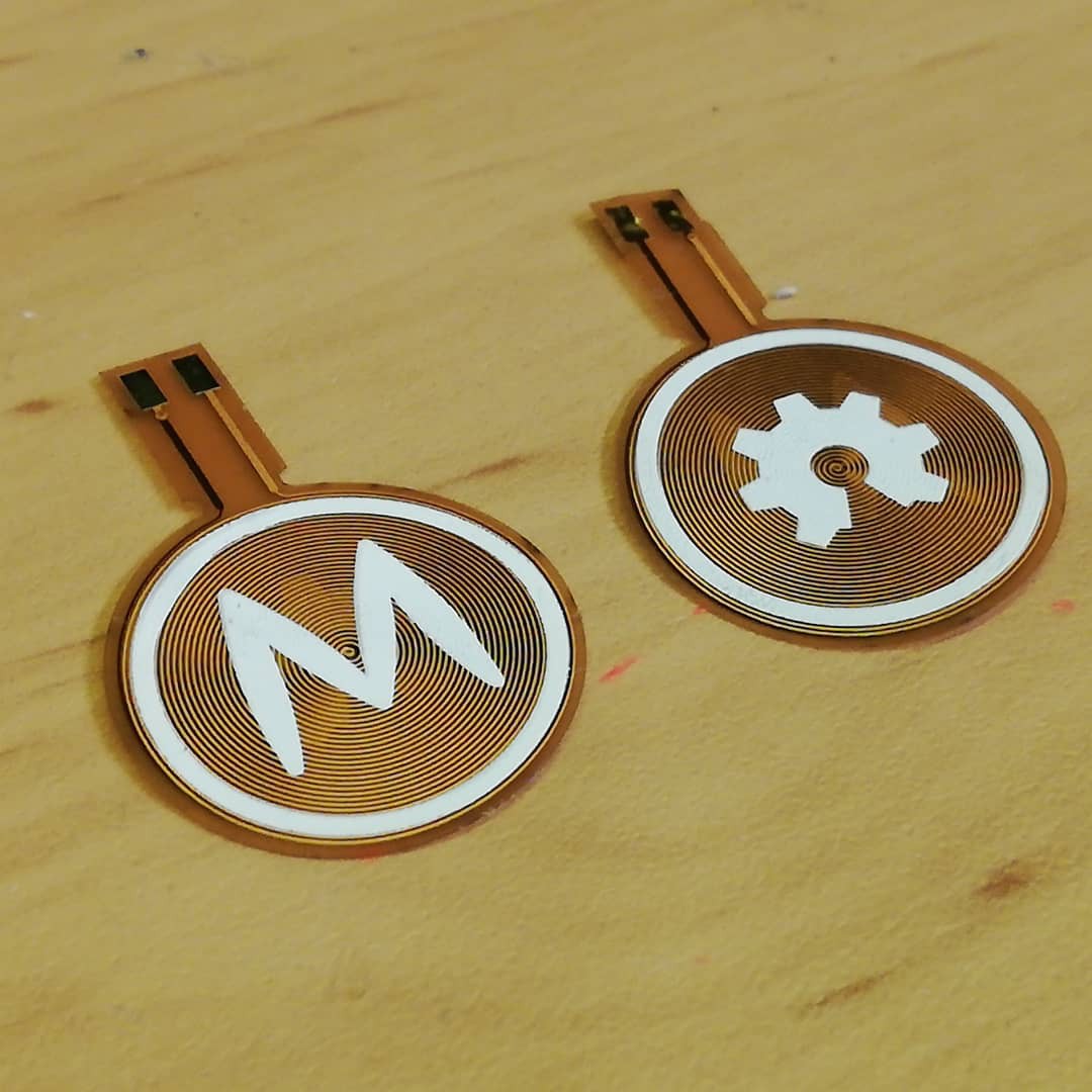
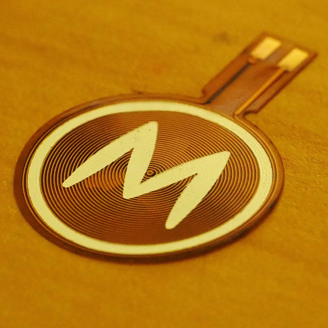
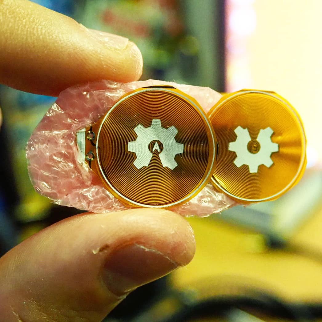
Flexible PCB Actuator
The thinnest Magnetic Actuator!
 Carl Bugeja
Become a Hackaday.io member
Already have an account? Log in.
Just one more thing
To make the experience fit your profile, pick a username and tell us what interests you.
Pick an awesome username
hackaday.io/
Your profile's URL: hackaday.io/username. Max 25 alphanumeric characters.
Pick a few interests
Projects that share your interests
People that share your interests


 Milad
Milad
 Aleksei
 Abduulah Omran
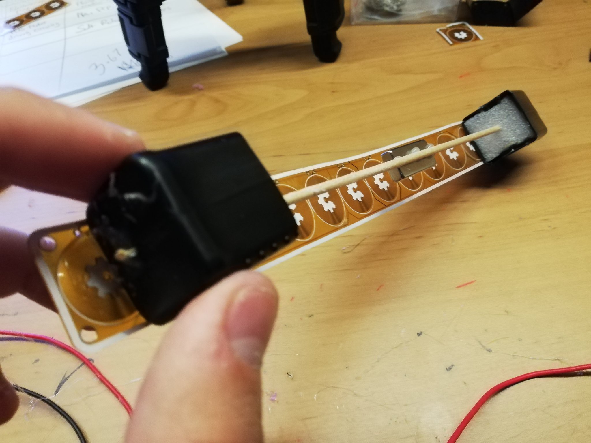
With a row of magnets underneath the strip, pull coil 1, push coil 2 and 3, pull coil 4. This will bend your strip like an omega. Release coils 1-3 and you have forwarded your strip by 1 coil, caterpillar way.