Close
0%
0%

MAX32660 Motion Co-Processor

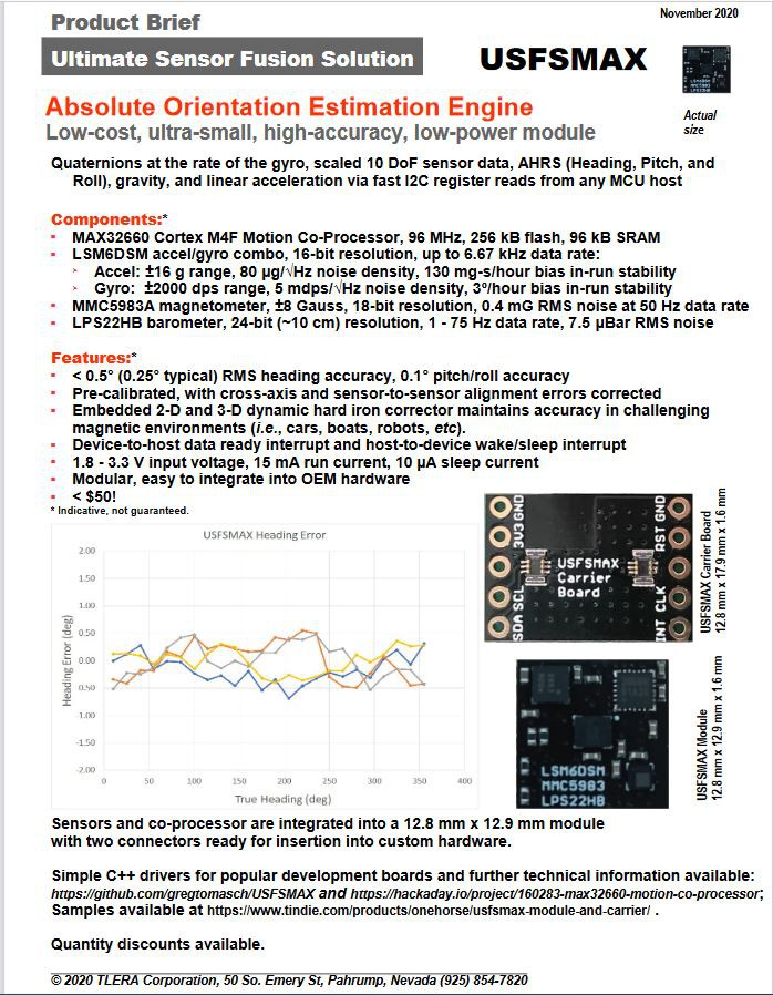
Super-small, ultra-low-power 96 MHz Cortex M4F co-processor manages sensors and processes data allowing the MCU host attend to other things.

Similar projects worth following
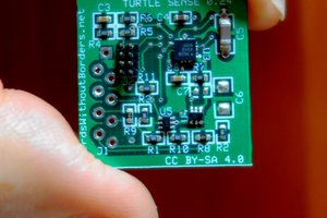
Small breakout board using the 1.6 mm x 1.6 mm MAX32660 96 MHz Cortex M4F MCU as a co-processor to manage LSM6DSM+LIS2MDL+LPS22HB inertial sensors and provide accurate absolute orientation and altitude estimation to the host via simple I2C register reads.

We have been using EM Microelectronic's EM7180 motion co-processor for absolute orientation estimation with some success. The EM7180 embeds a 10 MHz ARC processor with single-precision floating point unit (FPU) optimized for fast fusion calculations using fusion algorithms developed by PNI Corporation. The EM7180 off-loads the management of the sensors and the computationally-intensive fusion calculations from the host MCU so that accurate absolute orientation estimation in the form of quaternions or Euler angles can be read from the EM7180 by the host via simple I2C register reads. This means even a poky 8 MHz Arduino Pro Mini can obtain <2-degree accurate heading data when using the EM7180 co-processor and a suitably accurate sensor suite like the MPU9250 or LSM6DSM+LIS2MDL.

This may seem trivial when low-cost, high-performance MCUs like the STM32L4, nRF52832, ESP32 and others abound. And when computationally-efficient, open-source fusion methods have been available for years making it easy for anyone to get quaternions (see here and here and here and here) with these host MCUs.

However, accurate sensor calibration and fusion methods are not trivial to implement, so the demonstrated performance (< 2 degree rms heading accuracy) of the EM7180 is quite attractive. Also, the idea of a co-processor (commonplace in SoC computers in the form of sensor hubs and GPUs, for example) is to off-load specialized sensor management and computationally-intensive data processing tasks from the host. This allows the host's full attention to be placed elsewhere, and/or allows a power-gulping host to sleep through sensor management tasks thereby conserving power. And for hosts with embedded connectivity like the nRF52 (BLE) and ESP32 (BLE and wifi), the radio stack usually commands top priority so off-loading computationally-intensive tasks when possible minimizes collisions.

In addition to sparing the host and obtaining superb heading accuracy, the advantages of using the EM7180 as motion co-processor include small size (1.6 mm x 1.6 mm WLCSP-16), auto gyro and magnetometer calibration, simple I2C serial output, and ultra-low-power usage. Quaternions can be updated at the rate of the gyro (up to 400 Hz guaranteed), and there is some flexibility in the form of generic user registers, fusion tuning parameters, and the ability to make use of RAM patches to allow some customization of the fusion algorithms (for example, we have added fusion of the accelerometer and barometer to provide a drift-corrected altitude estimation). There is a warm start capability that allows the EM7180 to start with the last session's calibration parameters upon subsequent power up.

There are some disadvantages to using the EM7180, of course. These include the fixed, "black-box" nature of PNI Corp.'s algorithms stored in ROM, the need to load the sensor-specific firmware into RAM on each power up, the very small amount of free RAM that limits customization, behaviors of the fusion algorithm (especially the dynamic magnetometer calibration) that cannot be adjusted or turned off. While the EM7180 is sensor agnostic, meaning it can use the input of almost any I2C accelerometer, gyro, and magnetometer to produce fused quaternions, the drivers for the sensors have to be created and compiled using a deprecated compiler. The ~24 kBytes of compiled firmware have to be stored on an EEPROM for loading into the EM7180 RAM on each power up, or loaded from the host. Lastly, the EM7180 is designed to manage I2C sensors so that devices with SPI or UART serial interfaces cannot be used directly and require a translator.

With the announcement of MAXIM Integrated's DARWIN family of MCUs, especially the MAX32660, we have an opportunity to design a motion co-processor that offers all of the advantages of the EM7180 with few, if any, of the disadvantages....

Read more »

sensors-14-14885 (7).pdf

Accelerometer Tumble Calibratiion Detailed Reference

Adobe Portable Document Format - 1.18 MB - 11/27/2019 at 22:41

Preview
Download

OpenDocument Spreadsheet - 14.70 kB - 08/13/2018 at 19:59

Download

MAX32660.pdf

MAX32660 Data Sheet

Adobe Portable Document Format - 597.46 kB - 08/08/2018 at 23:56

Preview
Download

MAX32660 User Guide.pdf

MAX32660 User's Guide

Adobe Portable Document Format - 5.45 MB - 08/08/2018 at 23:54

Preview
Download

MAX32660_LSM6DSM_LIS2MDL_LPS22HD.v01a.zip

EAGLE design files and gerbers for prototype design

x-zip-compressed - 100.89 kB - 08/08/2018 at 22:42

Download

  • New Product Brief

    Kris Winer12/01/2020 at 00:04 0 comments

    USFS Modules and carrier boards are now available at Tindie.

  • MAX32660 Motion Coprocessor - MMC5983MA Low Noise Magnetometer Results

    Greg Tomasch08/11/2020 at 23:51 4 comments

    Update

    We have been moving forward with commercial sales of the MAX32660 motion coprocessor on Tindie. We are working closely with our initial users to address the remaining "kinks" in the product that inevitably come to light when real people start using something to solve real problems. Many Thanks to our early adopters!

    After resolving some initial issues, it is clear that the basic proposition of the motion coprocessor is holding up:

    • Superior performance from advanced sensor calibration done under controlled conditions and stored in the EEPROM
    • On-board dynamic hard iron correction to maintain calibration validity once deployed in the field

    Having said this, the question always remains: Can we reasonably do even better? One thing we wondered about was the magnetometer. Even with appropriate low-pass filtering it seems a bit noisy... So we suspected that heading accuracy and stability could improve further with a better magnetometer. Moreover, our current choice doesn't support a wide-enough operating temperature range for automotive applications. This second point is not a serious limitation at the moment. However, as part of a previous project, the notion of a motion coprocessor for automotive use was discussed. We determined that all of the necessary components were available in AEC-Q100-qualified versions except for a compatible magnetometer. 

    Kris periodically searches commercially available MEMS magnetometers for potential candidates. He recently identified the MMC5983MA from MEMSIC as a possible option. It boasts 18-bit resolution and AEC-Q100 qualification with a 400kHz-capable I2C interface. The current MAX32660 motion coprocessor product uses the LIS2MDL magnetometer offered by ST Micro. This particular triaxial magnetoresistive magnetometer responds over a full scale range of +/-50G at 16-bit resolution. The operating temperature range is -45 to +80C. The typical RMS noise level we measure for this magnetometer is ~0.35uT on each axis. The resulting RMS heading noise is ~0.1deg under static heading conditions.  The MMC5983MA is also a triaxial magnetoresistive sensor, has a full scale range of +/-8G at 18-bit resolution and can operate between -40 and 105C. The nominal RMS noise is estimated to be 0.04uT for each channel. 

    MMC5983MA Testing and Results

    From the perspective of specifications, the MMC5983MA does look attractive. It does cover a much smaller full scale range but +/-8G should be adequate as the geomagnetic field is ~0.5G. This means that the MMC5983MA can tolerate a hard iron offset up to ~7G without saturating, which should be adequate for the vast majority of applications. We did find the advertised reduction RMS noise and 18-bit resolution to be compelling, despite the nearly 2x increase in price compared to the LIS2MDL. 

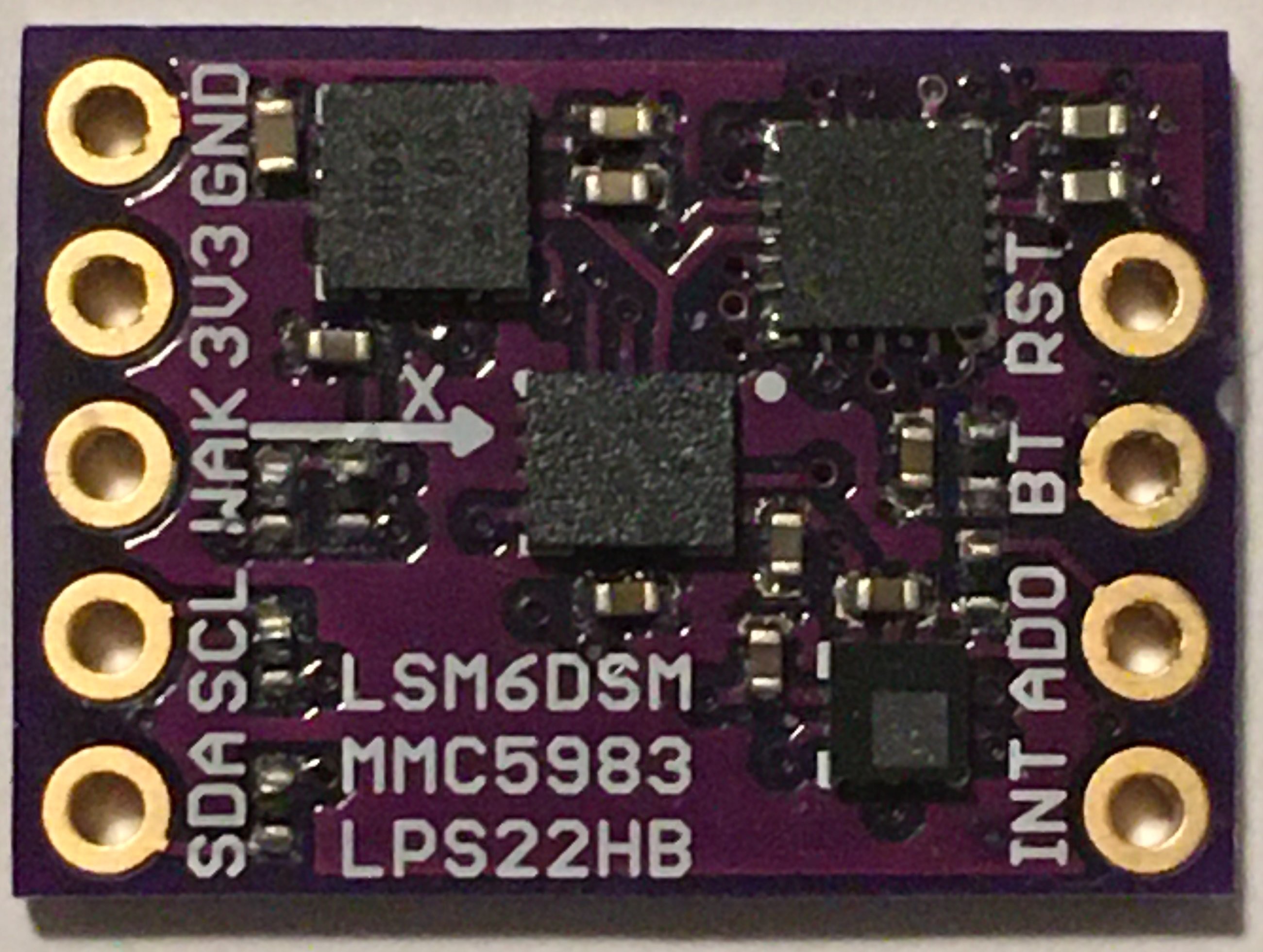
    In order to satisfy our curiosity, Kris designed a prototype version of the MAX32660 motion coprocessor using the LSM6DSM accel/gyro, MMC5983MA magnetometer and LPS22HB baro:

    And I wrote a version of the firmware to support the MMC5983MA. This chip has a few quirks regarding the data ready interrupt but it does deliver high quality data at 100Hz without disrupting data collection from the other sensors on the MAX32660's  master I2C bus.

    The initial data sets from this variant of the MAX32660 motion coprocessor verifies the noise improvement promised in the MMC5983MA datasheet. The magnetometer's RMS noise level ranged from 0.02 to 0.03uT across the three axes, just about 10x better than the results observed for the LIS2MDL. This improvement in magnetometer noise resulted in an RMS heading noise level of 0.015deg under static heading conditions. This is about a 7x improvement over the current LIS2MDL version.

    Finally, we wanted to see if the MMC5983MA's reduced noise and improved precision would translate into better RMS heading error. Kris built two MMC5983MA-based prototype units and I subjected...

    Read more »

  • Unit-to-Unit Variation and On-Board Residual Hard Iron Error Correction

    Greg Tomasch12/20/2019 at 00:44 1 comment

    Unit-to-Unit Heading Accuracy Variation

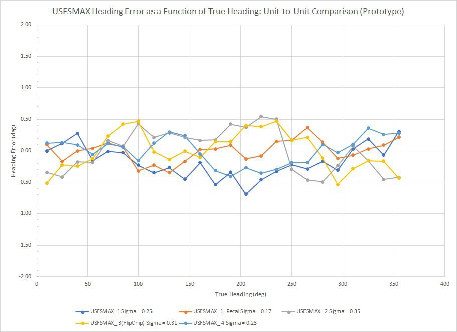
    In my last log entry I mentioned the need to characterize the unit-to-unit variation of heading accuracy among professionally manufactured MAX32660 motion co-processor boards. We are still waiting for delivery of our initial production runs, so in the mean time I decided to characterize the four prototype units I had on-hand. I used the same precision goniometer, calibration method and experimental procedures described in my previous log entry. The plot below shows heading error as a function of heading.

    Results from a total of four units are included in this plot with two data sets from "Unit 1" representing two different trials of the calibration method. The RMS heading error ranged between 0.17 and 0.35 degrees. If anything we would expect professionally manufactured units to have more precise location/alignment of the MEMS sensor chips on the circuit board than these hand-built prototypes. So if placement of the accel/gyro and magnetometer chips effects post-calibration heading accuracy, we might potentially see less unit-to-unit heading accuracy variation on production units than what I have measured here. However, the nature of the 24-point tumble calibration described earlier should robustly correct accel/gyro/mag misalignment. So I would expect these results to be a representative sample of the MAX3260 motion co-processor's heading accuracy capability. I will perform similar measurements on a sample from our first run of production units when they arrive early in 2020.


    On-Board Real-Time Hard Iron Error Correction

    Throughout the slate of heading error characterizations I have performed, I noticed that heading error performance degrades slightly when the magnetic environment differs from the exact calibration conditions. This effect is not gross but is more like degrading from ~0.26 to ~1 degree RMS heading accuracy. This illustrates a typical complaint regarding IMU calibration: The stellar results generated during calibration on the test bench are seldom translated to the real performance in the field. Analysis of the heading error plots showed that the additional error is hard-iron-like in that it has a period of 360 degrees. This means the magnetometer response surface is still spherical but is displaced from the origin.

    The heading error results shown above indicate that the suite of MEMS sensors we are using  (LSM6DSM and LIS2MDL) are stable enough to deliver ~0.26 degree RMS heading accuracy... So degrading to ~1 degree by incidental changes in the IMU's local environment should be correctable, especially since the additional error takes the form of a hard iron offset (the easiest to estimate and correct). The MotionCal (Freescale) magnetic calibration algorithm embedded in the MAX32660 is quite capable of dealing with this additional incidental hard iron error but it is too computationally intensive to run in parallel with the main AHRS fusion filter in real time.

    Instead of just saying, "Oh well, such is life..." I decided to investigate the possibility of a simple, computationally efficient method of fitting a sphere to the locus of run-time (Mx, My, Mz) data points and extract estimates of the residual hard iron offsets. I found this reference which presents a practical embodiment of a method for geometrically fitting the "best sphere" through a 3D ensemble of data points. Upon examination, I particularly liked this method because 1) It is analytic and does not need to be solved iteratively and 2) Adding data to the point ensemble to be fitted only results in using more memory without increasing the computational load on co-processor MCU. The center point and radius of the best-fit sphere are calculated from a set of running sums that are cubic in X and Y. Executing a spherical fit after adding a new (Mx, My, Mz) data point consists of:

    • Calculating the necessary cubic and quadratic terms from the Mx, My, Mz data
    • Adding new terms to the running cubic,...
    Read more »

  • MAX32660 Motion Coprocessor - Initial Results

    Greg Tomasch11/27/2019 at 00:29 5 comments

    Sensor Calibration and Performance Testing

    Calibration

    Many people seem to think that good orientation estimation results are primarily due to some "Special sauce" contained in the sensor fusion algorithm. In fact, few consider there to be any significant differences between the various MEMS sensor products offered by different manufacturers. The reality of it is that there is no such thing as an algorithm that can correct poor quality accelerometer, gyroscope and magnetometer data to give excellent orientation estimation results. We have shown that once the non-ideal behavior of the accelerometers and magnetometers have been neutralized through effective sensor calibration, any effect of the particular fusion algorithm on orientation estimation accuracy is secondary. Consequently, in the development of the MAX32660  motion co-processor I focused on making firmware infrastructure that can:

    • Perform sophisticated sensor calibrations using embedded routines and store the results in the co-processor
    • Reduce run-time implementation of the various sensor calibrations to simple, calculationally efficient forms

    The need to embed complicated calibration functions and perform a significant volume of additional floating point calculations figured prominently into the selection of the MAX32660 for an advanced motion co-processor; it has a lot of memory and floating point processor power in a small package.

    A short discussion of what constitutes effective accelerometer and magnetometer calibration would be helpful at this point. We will consider the magnetometers first. For a perfectly calibrated three-axis magnetometer, the Mx, My, Mz response surface is a perfect sphere centered at the origin. "Hard iron" errors occur when there is a static magnetic field in the magnetometer's reference frame that displaces the response surface from the origin by a constant vector. "Soft iron" errors result from magnetic flux divergence and are manifested as the response surface being distorted from a sphere to an ellipsoid. Both types of error can be corrected by fitting an ellipsoidal surface to uncorrected 3D magnetometer data and then transforming back to a sphere with no offset vector. Freescale Semiconductor (now NXP) published a good C library to fit the uncorrected magnetometer data and generate both soft and hard iron calibration corrections. This library is included in the "MotionCal" application distributed by Paul Stoffregen of PJRC. I started with the code in Paul Stoffregen's GitHub repository and re-cast Freescale's solver for embedding into the motion co-processor. This works quite well and consistently results in residual fit errors of <= 1.5%.

    Effective accelerometer calibration is also essential to achieve accurate estimates for heading, as well as pitch and roll. There are numerous methods for correcting accelerometer imperfections including:

    • Bias (zero-point offset)
    • Scale error
    • Non-orthonormality of the x, y, z sense axes

    Of all the potential accelerometer calibration techniques in the literature, the "Tumble" method seemed the most suitable for the purposes at hand. By collecting raw ax, ay, az data in a number of orthogonal orientations, the accelerometer errors listed above can be quantified and calibration corrections accurately estimated.

    The final category of sensor non-ideality that needs to be addressed is relative rotation between magnetometer and the accelerometer (inertial) sense axes. This turns out to be important because the pitch and roll angle estimates are derived from the 3D accelerometer data. Pitch and roll are used to resolve the 3D magnetometer components from the sensor reference (body) frame into the horizontal plane of the world reference frame for heading estimation. This is true for quaternion-based fusion filters as well as explicit direction cosine rotation-matrix-based projections of the magnetic field vector. Fundamentally, relative rotation of the inertial and magnetometer sense axes...

    Read more »

  • Final Hardware Design

    Kris Winer11/19/2019 at 01:01 0 comments

    November 18, 2019

    As Greg mentioned in his log, we are making good progress on the motion co-processor firmware. We are also getting ready for pilot production of the hardware next month and are considering options for the 0.5 x 0.7 in. product board.

    The baseline is the same design we have been using for testing, more or less.

    Baseline MAX32660 motion co-processor design pcbs from OSH Park

    This design uses the 0.4-mm-pitch,  3 mm x 3 mm MAX32660GTG+ TQFN-24 package (without bootloader) and the LSM6DSM, LIS2MDL, and LPS22HB (10 DoF) sensor suite. We have dropped the 32.768 kHz crystal, since this is only needed if the MAX32660 RTC is required, which it is not in this application. We have also added a bypass capacitor to nRST that eliminates spurious device resets (good practice in any case). We have added 10K pulldowns to the formerly SWD port, one for an I2C address pin and one to put the MAX 32660 into boot mode, which returns these two pins to an SWD port for reprogramming.

    The advantage of this design is the inexpensive manufacturing using OSH Park design rules (for 4-layer pcbs). This makes it possible for anyone to easily customize this open-source design for their applications as well as reduce the per-board cost of manufacturing. The disadvantage is the "large" size of the MAX32660 package. This makes it necessary (for this board size) to drop one of the plated through holes, which will complicate mounting onto popular development boards like the Teensy or Dragonfly but should pose no problem for breadboard use.

    The alternative design uses the 0.35-mm-pitch, 1.6 mm x 1.6 mm MAX32660GWE+ WLP-16 "flip chip" package (without bootloader).

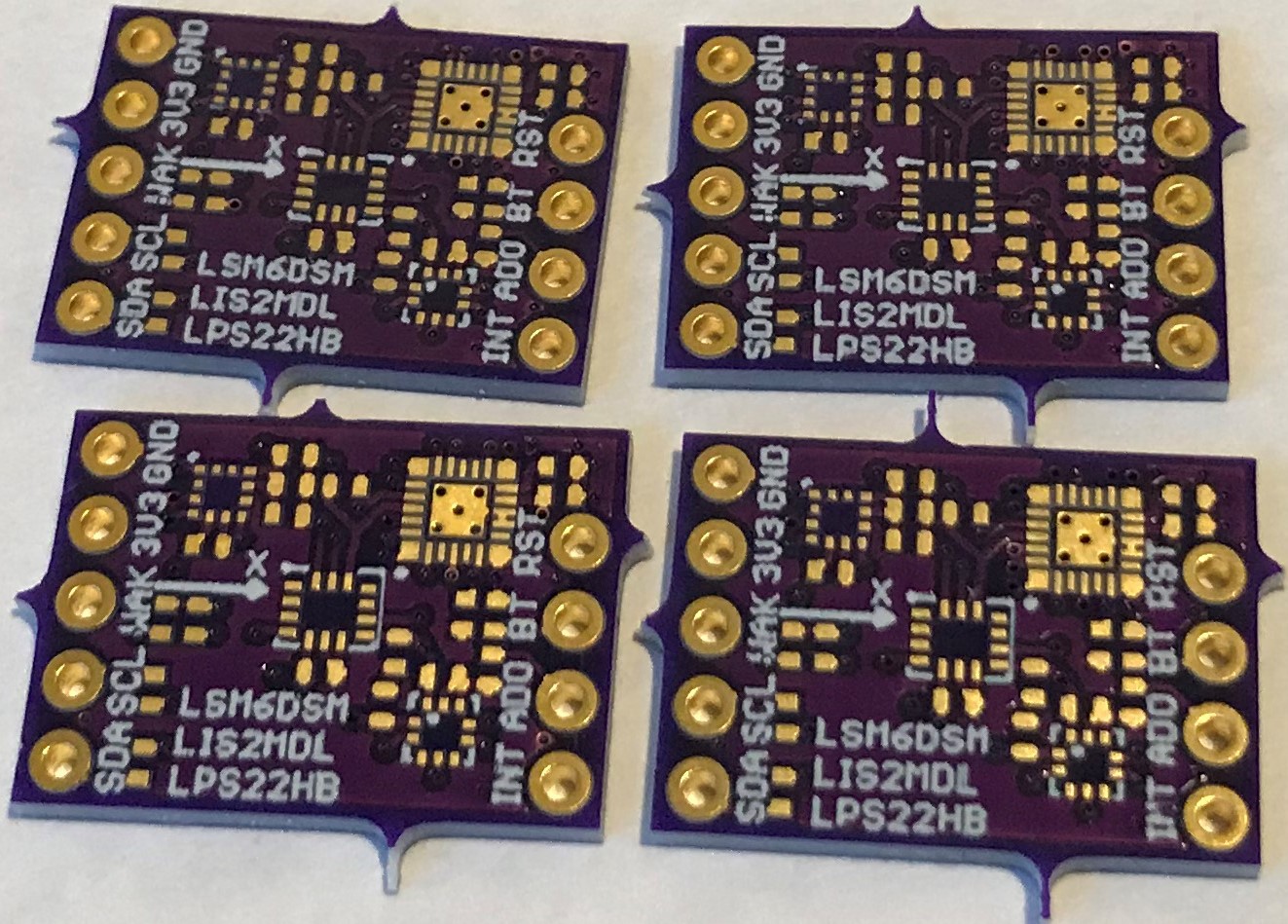
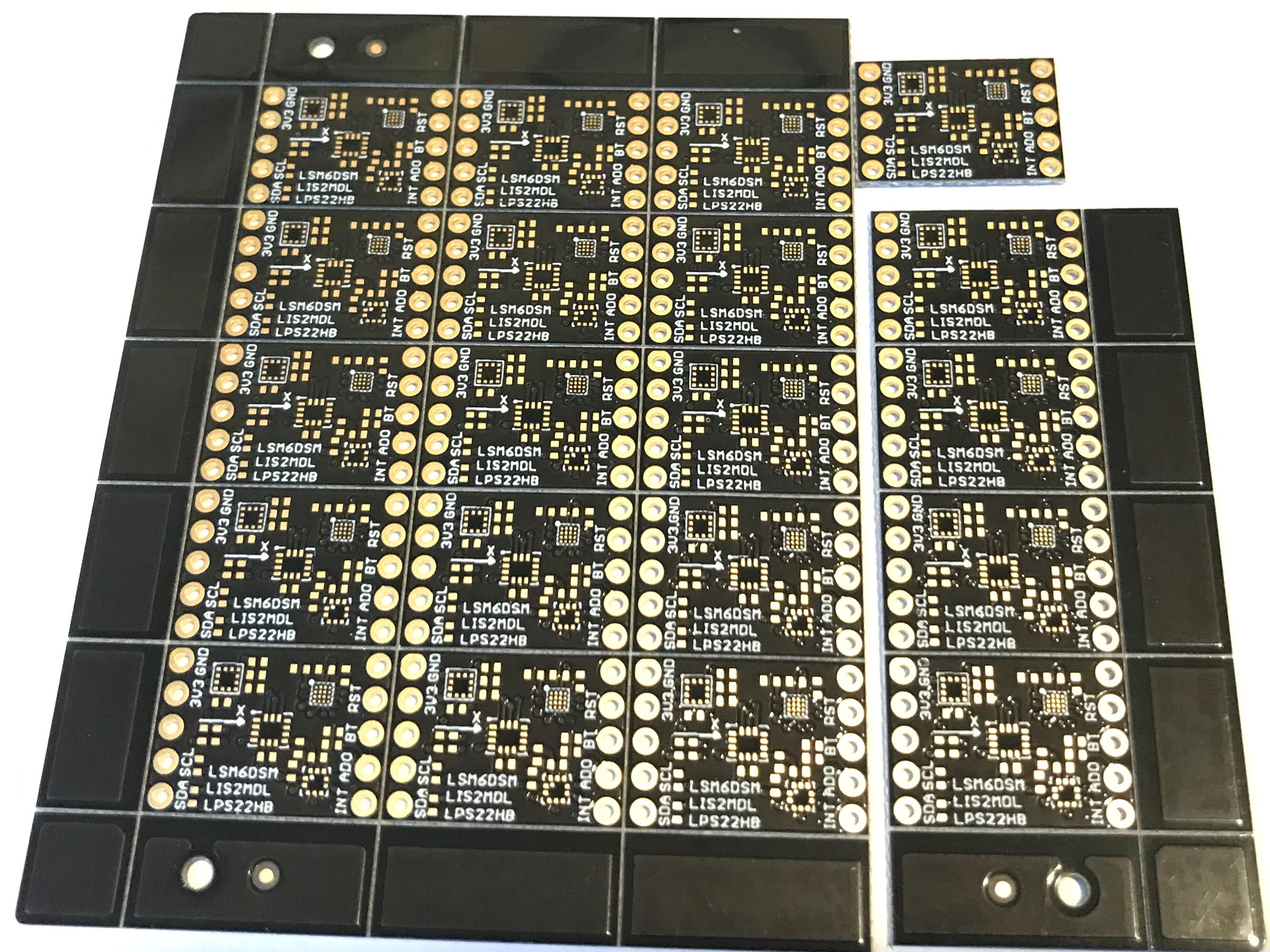
    Twenty-board panel from Sunking Circuits.

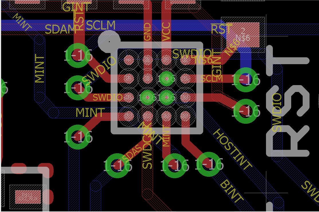
    All 16 of the pins are required for the design including the four internal pins; one is connected to GND and three are connected to SDAM, SWCLK, and host INT. I used EAGLE CAD to design this version and had to violate OSH Park design rules in order to place 3 mil vias onto these three internal pins:

    This would never work since the via annuli are too close together. This is an especially difficult part to design with since the pitch is 0.35 mm and the pads are 0.18 mm in diameter, both 10-15% smaller than most other WLCSPs I have dealt with, including the EM7180. Fortunately, I found a cooperative fab house (Sunking Circuits Electronic LTD) who took the design and modified it to conform to their via-in-pad process:

    Board layout of the pin pads after rework by Sunking.

    According to Sunking "there will be solder mask covering the three rings of the resin plugged vias, the yellow parts will be the exposed pads, their final diameter will be 0.18 mm with a tolerance of +/- 20%."

    The first batch had to be scrapped because of some kind of debris in the production process, but I just received the second "good" batch which passed their internal testing and look marvelous:

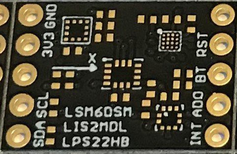
    Close up of the second design option.

    The cost was ~$16 per board for 20 of them delivered including the $200 NRE for setup on every new pcb design, high by OSH Park standards but not prohibitive. And certainly much cheaper than I could have had this work done locally in Silicon Valley. This means that if I produce 100 of these at Sunking the pcb cost would likely be about ~$5 per board instead of the ~$1 per board the baseline design might cost.

    So this extra cost and the added complexity of the production are definitely a disadvantage. The advantage is that we get back the missing PTH at the board corner, and maybe a cleaner design. Not sure it is worth it. But this was a useful learning experience in that there are many 0.4-mm-pitch WLSCP devices that I would like to be able to use that are now within range of my design abilities and pocketbook.

    The next challenge is assembling one or two of these boards and testing them for function.  We'll post some comparative testing results in a future log soon.

    I am sure we will go...

    Read more »

  • MAX32660 Motion Co-processor Firmware Development Challenges

    Greg Tomasch11/17/2019 at 02:33 3 comments

    Well, it has been a long while since any log entries have been posted for this project... That is not because Kris and I haven't been working on it but because there have been some serious software development challenges to overcome.  It is one thing to try out some of the simple I2C loop-back examples in Maxim's software development kit (SDK) or blink an LED but it is a fundamentally harder task to make the MAX32660's peripherals perform to the level required by a high-speed asynchronous sensor fusion engine.

    I'm happy to report that the "show-stopper" software infrastructure problems preventing a robust, high-performance motion co-processor implementation on the MAX32660 have been solved. We have demonstrated reliable operation and excellent attitude estimation results from MAX32660-based parts. I plan to open a new project to document general motion co-processor calibration/characterization instrumentation and procedures soon. Results from the MAX32660 motion co-processor will figure prominently into this effort. The remainder of this log entry will be an overview of the firmware development challenges and what it took to overcome them.

    When I set out to write motion co-processor firmware for this micro-controller, I already had almost all of the necessary algorithmic and calibration "pieces" in-hand and successfully implemented on other micro-controllers. This should be the hard part, right? Not so fast... There are some other basic pieces of "data  plumbing" that are absolutely essential to make a motion co-processor work on any micro-controller:

    • An EEPROM emulator to store co-processor configuration information and sensor calibration data for retrieval at startup
    • An asynchronous I2C master bus; sensor data ready (DRDY)  interrupts initiate an I2C data read transaction from the appropriate sensor with a completion callback to the main sensor fusion loop
    • An asynchronous I2C slave bus; the host micro-controller (connected to the MAX32660) must be able to query the co-processor for data and receive a prompt response without significantly delaying the main sensor fusion loop
    • Rising-edge-interrupt-capable GPIO pins to handle sensor DRDY interrupts.

    After an initial assessment of Maxim's SDK, it became clear that only the rising-edge interrupt capability would be straightforward. I addressed the other three items in this order:

    1. EEPROM emulator
    2. Asynchronous I2C master bus
    3. Asynchronous I2C slave bus

    I should say that if any one of these capabilities could not be successfully implemented on the MAX32660, completion of the project would not be worthwhile. The final product would simply not be competitive. Before I proceed much further, I want to acknowledge the fact that I was very lucky to have an excellent teacher/mentor along the way. Thomas Roell is truly a master at micro-controller application programming interface (API) development and he shared his expertise with me generously. Without his inputs and help along the way it would have certainly been much, much harder to bring the project along this far.


    EEPROM Emulator

    An EEPROM capability is crucial for a motion co-processor. The basic proposition here is that we are using economical MEMS sensors as the inputs into the fusion/attitude estimation algorithm. No matter what, there is no algorithm that compensates for bad sensor data... So good sensor calibration is a prerequisite to achieve an accurate attitude estimate. Since MEMS sensors can significantly depart from ideal behavior, effective calibration may require more involved procedures performed under controlled conditions. The calibration procedures generate parametric corrections that are applied at run-time. If the sensor calibration procedure(s) are impractical to do each time at startup, the sensor correction parameters need to be available in non-volatile memory (NVM). 

    The basic idea behind an EEPROM emulator is that part of the micro-controller's flash memory is set up to mimic...

    Read more »

  • Some Power Measurements

    Kris Winer08/25/2018 at 01:15 5 comments

    August 24, 2018

    First some housekeeping. I learned from Maxim that there was a typo in their data sheet (since corrected) and that the MAX32660 roadmap only includes three device packages: the 1.6 mm x 1.6 mm WLCSP-16, the 4 mm x 4 mm TQFN-20, and the 3 mm x 3 mm TQFN-24 that we are using in our prototype development. No 1.6 mm x 1.6 mm TQFN-16 package :<  We will have to make do with the 3 mm x 3 mm version or bite the bullet and go for more expensive fab methods (or zGlue) and use the WLCSP for minimal size. For the moment we will stick with the 3 mm x 3 mm TQFN-24 IC since it is easy to assemble and has lots of pins for firmware development work.

    I have heard that a revision to this TQFN-20 package is due in a month or so that corrects/improves the silicon. Still trying to find out more details but the changes should include improvements in power usage. That is what I want to discuss now.

    I finally (with Maxim's help) figured out the low power sector of the MAX32660 and have started doing some preliminary power testing. The low power scheme is a bit different from the STM32L4. There are three core voltages that can be selected which are equivalent to setting the high-speed clock to 96 MHz (OVR= 1.1 V, default), 48 MHz (OVR = 1.0 V), or 24 MHz (OVR = 0.9 V). The actual voltage is an allowed range and lowering this range effectively selects a lower clock speed. Then, for each range the clock can be further divided by 2^N where N can range from 0 to 7. It sounds complicated but in fact it is straightforward to select amongst these limited choices and the effect on average power usage can be quite large. For example, with a simple blink program at 96MHz (OVR = 1.1 V) default the MAX32660 uses 11.1 mA (when the led is off but MCU active). At the lowest core voltage setting (OVR = 0.9 V, 24 MHz) the blink program uses 5.1 mA when using low power sleep mode between RTC alarm interrupts. Let me explain this...

    The way most programs we will be using work is to configure everything at the start of the program (like setup in Arduino) and then run a forever loop where all actions are interrupt driven (sensor data ready interrupts, timer interrupts, RTC alarm interrupts, etc). This is so when an interrupt is not being serviced, the MCU can sleep in a low-power state.

    So for the simple blink program, we set the RTC alarm to trigger an interrupt every two seconds. The interrupt wakes the MAX32660, it takes some action (turns the led on or turns the led off) and then goes back into SLEEP mode. The program uses 11.1 mA at 96 MHz without invoking SLEEP mode between interrupts and 9.6 mA when SLEEPing between interrupts. The average power drops to 5.1 mA when running at 24 MHz with SLEEP between interrupts. This demonstrates the benefit of the SLEEP scheme as well as selecting the clock speed appropriate to the task, and it just makes common sense to take advantage of these features as a general strategy.

    The wake up time from SLEEP mode is very fast (a few us). There is also a DEEPSLEEP mode with a somewhat longer wakeup time (~1 ms), and using this instead of SLEEP at 24 MHz (OVR = 0.9 V) drops the average power down to 175 uA. About 6 uA of this is just due to the sensors in power down mode on the custom board. This (~169 uA) sounds like an impressive power savings and it is much lower than 5.1 mA, but the data sheet says we should be at ~4 uA. So some more fine tuning is required like turning off peripherals that aren't needed (like SWD) and making sure all GPIOs not being specifically used are tri-stated, etc. to get the power as low as possible.

    Also, the pending silicon revision should reduce this 1 ms wake up time considerably. Still lots of work to do to get the power sector under control. The goal is 1 mA or less when running the motion co-processor in its normal mode, meaning accel and gyro at 208 Hz, mag at 100 Hz, and barometer at 10 Hz with quaternions at the rate of the gyro.

    ... Read more »

  • First Successful Programming of MAX32660

    Kris Winer08/14/2018 at 01:29 7 comments

    August 13, 2018

    As soon as we tried to program our custom MAX32660 motion co-processor board we knew we had a problem. The MAX32625 PICO DAP debugger which came with the MAX32660 evaluation kit and the MAX32625 PICO debugger we bought separately both interface with the MAX32660 target via a 2 x 5 SWD 0.05-inch connector, which of course, we didn't put on our tiny 0.7-inch x 0.5 inch breakout board; no room! We did expose SWDIO and SWDCLK as well as nRST on the breakout board edges. That is, we expected to have to use the SWD port to program our breakout. We just didn't think it would be so hard to do so.

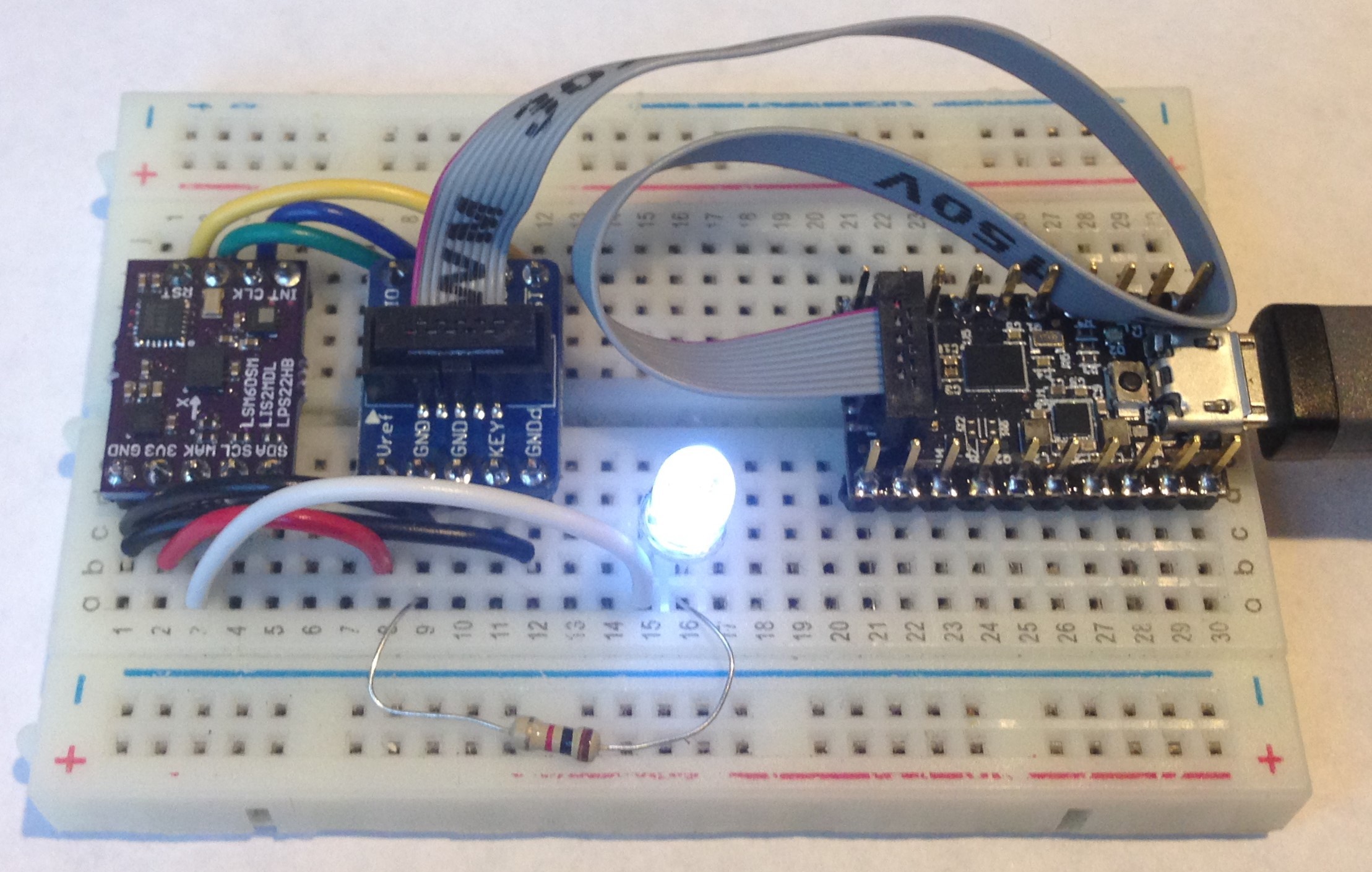
    First we tried to use the edge pins on the MAX32625 debugger which are supposed to connect to SWD and nRST, etc but we couldn't make this work. Not sure why. Programming via the SWD connector did work on the evaluation board so we ordered some SWD cable breakout boards from Adafruit (faster than making our own), which allowed access to all of the SWD signals from the 0.05 inch cable. And...success! Simply connecting SWDIO, SWDCLK, GND, nRST, and VREF to 3V3 and we were able to program the custom board MAX32660 to toggle one of the GPIOs we exposed as WAKE on our breakout. The toggled GPIO then actuates an led and voila:

    Here we have GND_detect also connected but we subsequently learned this is not needed.

    Yes, it is a little clunky but for prototype hardware and firmware development this works just fine. In the end-user application, once programmed with firmware the breakout doesn't need to be programmed again. The breakout will communicate with the host MCU via I2C in use. So in reality for the final product we don't need SWD and nRST exposed to the user; and it is a shame to waste valuable board edge just for one-time programming. So we will likely expose the SWDIO/SWDCLK, and nRST along with GND and 3V3 as a 2 x 3 test pad pattern on the back of the board that can be programmed at the fab using a pogo pin connector.

    This was the last technical hurdle to overcome for proof of concept. Now we will continue our firmware development and, in a few days, test the board as a motion co-processor to an STM32L4 host MCU. Very exciting!

View all 8 project logs

  • 1
    USFSMAX Pin Header Soldering Instructions

    Note: Recent Testing has shown that overheating the magnetometer can undermine calibration validity and cause loss of heading accuracy. Caution should be exercised while soldering pin headers or other connectors to the USFSMAX board. We specifically recommend:

    • Use fine gauge, high quality 60-40 or 63-37 Pb/Sn electronic grade flux-core solder
    • Sn-based ROHS-compliant solders are not recommended due to their higher melting/flowing temperatures
    • Use a good quality soldering iron with a fine, clean tip. It should be the right temperature to cause solder to flow between the pin and plated through-hole in a few seconds. Too cold will require excessive contact time for the solder to flow, overheating the board. Too hot can cause damage to the plastic pin header block and delamination of the plated through hole pads
    • Insert both rows of solder pins on both sides of the USFSMAX board, align them properly and hold them in place
    • Verify that the soldering iron and solder quickly make a good joint by testing on the “INT” or “ADO” pins first
    • The “GND” and “3V3” pins are the closest to the magnetometer; try to keep soldering iron contact down to 1 – 2s. Only electrical contact is required for these pins
    • DO NOT solder the pins sequentially “In a row” down one side. This concentrates too much heat into a small area of the USFSMAX board. Instead, solder one pin and then skip to the next pin that is furthest away. If there is any question that the board is getting hot, stop and let it cool

View all instructions

Enjoy this project?

Share

Discussions

kdharbert wrote 02/17/2021 at 18:40 point

Since this unit has an onboard ARM processor, has there been any thought given to building FW modifications that can directly integrate with a wireless unit?  I presently am using Teensy MCUs as an intermediary between IMU and wireless.  Ideally I could, have two of the carrier boards: one mounted to the Teensy and the other mounted to the wireless unit. I could program the IMU on the Teensy and then remove it and attach it directly to the second carrier mounted to the wireless unit. 

  Are you sure? yes | no

Scott Bierly wrote 04/20/2020 at 19:37 point

Hi Kris, I see you continue to be active on many fronts, including IMU perfection! We are currently doing an integration based on your USFS, and I'm intrigued at this version which opens up the box a bit.  I see all the PCB design files and the reference paper, but I don't see any information about how to actually use this board or download the software--where is this located? Thanks!

  Are you sure? yes | no

Kris Winer wrote 04/20/2020 at 20:30 point

Hi Scott,

We are working on posting the Arduino sketches on github along with a wiki describing its use. We have a link to the register map on the Tindie product page. In general, we are slowly building out the support infrastructure for this as a product including setting up reliable supply. We have about 100 of the pilot production boards we are currently selling to fund the next production batch. 

The firmware will not be posted, but will be available under license, etc.

For further discussion please e-mail me at tleracorp@gmail.com.

  Are you sure? yes | no

KD9KCK wrote 10/06/2020 at 18:14 point

Does this mean that this board has the same disadvantage as the EM7180 being sort of just a "black box" with unknown algorithms in it?  Just that with this board there are more config options?

  Are you sure? yes | no

Kris Winer wrote 10/06/2020 at 19:31 point

Yes and no. We have access and control over every aspect of the firmware and we continue to improve and augment it. But we do not plan to make the firmware or its methods open source. So from the retail customer point of view, the firmware is more or less a black box.

  Are you sure? yes | no

Alex wrote 04/15/2020 at 00:47 point

Hi Kris, this and your other work on IMUs are indeed great.  Any update on this project?  I'm looking to integrate an IMU (perhaps this one) into one half of an adafruit feather add on for a wearable sensor... would you recommend this, or something more tried and true?

  Are you sure? yes | no

Kris Winer wrote 04/15/2020 at 00:55 point

Not sure what I would recommend without understanding your requirements. But the MAX32660 boards are available on Tindie (https://www.tindie.com/products/onehorse/max32660-motion-co-processor/) as of this week so you can test them against other likely candidates. The MAX32660-based solution is for applications that require the most accurate heading estimation (0.3 degree rms typical) and dynamic hard iron correction (needed when mounted in/on a vehicle like car, plane. boat, etc). The EM7180 version works well too, costs a bit less and produces heading accurate to 1 - 2 dgrees rms and has some dynamic magnetic calibration. Maybe good enough for your application? It is not too expensive to try several possible solutions....

  Are you sure? yes | no

Alex wrote 04/15/2020 at 01:11 point

The application is to record movements of operators performing various tasks with their arms and hands (picking up and using instruments).  There are two or more operators performing tasks simultaneously, so I'm using it to see who is doing an action and when.  I'm having the Feather M0 WiFi - ATSAMD21 + ATWINC1500 stream that data and indoor location data (decawave) over wifi to a server for timestamped recording.  Currently, I have an add on ADXL345 accelerometer, but I would like to replace that with an IMU since it may give more insight into the movements.  To keep things wearable, I'd be taking the design and putting it onto half of a feather formfactor PCB (the DWM1000 module will be on the other half) so I will indeed buy one from you but ultimately the goal is to fabricate one myself with the decawave module so it's a compact package that can be attached to the upper arm.  Will the firmware you write for the MAX32660 sensor fusion be released?  This is for an academic science project.

Thank you.

  Are you sure? yes | no

Kris Winer wrote 04/15/2020 at 05:38 point

You might be better off with an LSM6DSO that has an embedded finite state machine and machine learning for gesture recognition, etc. I have a github repository with arduino sketches and examples of how to use this.

The USFSMAX firmware will not be open sourced, but will be available under license. The hardware design and register map are open source and available from the Tindie page.

  Are you sure? yes | no

Daniel wrote 05/07/2019 at 17:33 point

Hi Kris.
Is this project still active? :)

  Are you sure? yes | no

Kris Winer wrote 05/07/2019 at 17:46 point

Yes. We have been working on the software side of things and have methods for calibration and sensor fusion that allow < 1 degree rms heading (typically 0.5 degree rms) accuracy routinely as well as magnetic anomaly detection/correction so the heading (i.e., absolute orientation) remains accurate even in the presence of external magnetic fields.

We are testing these now using a 2-stage goniometer and will update the project with results soon. But excellent fusion on the host MCU is working well.

We are still debating the best co-processor. We'd prefer to use the STM32L4 but this is rather larger than we would like. The MAX32660 is still a candidate as is the EM7180, and we might even bite the bullet and try to use the 1.6 mm x 1.6 mm WLCSP, although this would be an expensive pcb.

The hard part of the project is done. Realization as a motion co-processor still needs to be reduced to practice but I see no barriers to straightforward implementation. Just a question of the best vehicle for it.

  Are you sure? yes | no

Daniel wrote 05/08/2019 at 15:56 point

Wow, thanks for the reply!
It's really amazing work! :)

  Are you sure? yes | no

Kevin wrote 02/13/2019 at 00:25 point

How is it going? Did they get the quirks worked out of the power management?

  Are you sure? yes | no

Kris Winer wrote 05/07/2019 at 17:37 point

Sorry missed this. I haven't tried the latest silicon so I don't know yet.

  Are you sure? yes | no

John Stockton wrote 12/12/2018 at 02:08 point

Nicely done Kris.  Have you looked at some of the newer AK parts like the AK09917D since the original AK8963 looks like it is hard to get (maybe EOL)? 

  Are you sure? yes | no

Kris Winer wrote 12/12/2018 at 02:47 point

The LIS2MDL is superior to the AK line of Hall-sensor-based mags both in terms of lower power and lower jitter. In general, the current ST sensor suite (LSM6DSM + LIS2MDL + LPS22HB) is the best available of the "cell-phone" IMU sensors (in the few dollar price range) and is a good replacement for the MPU9250 + MS5637 barometer suite. The ST sensor suite offers low cost, very low power, superb stability and reproducibility and we have been able routinely to obtain ~1 degree heading accuracy using it. Good enough for me...

  Are you sure? yes | no

Kris Winer wrote 08/18/2018 at 15:35 point

Maxim has an Eclipse-based SDK for the MAX32660. But GCC-make also works as does mbed.

  Are you sure? yes | no

don.vukovic wrote 08/18/2018 at 15:15 point

What compiler/IDE do you use for this part ?

  Are you sure? yes | no

Martin Pålsson wrote 08/14/2018 at 19:52 point

Another great board Kris!

I see that you have kept the edge breakouts more or less the same as the USFS-MPU9250 (the essential pins, I2C gnd and 3v3). Seems like it will be a drop-in replacement, well done!

Question: will the axial alignment be the same as for the USFS-MPU9250? 

Best regards

Martin

  Are you sure? yes | no

Kris Winer wrote 08/14/2018 at 20:17 point

This is just a prototype so nothing is fixed as of yet. We kept the alignment the same as the EM7180 version of the board, that is the one with the same ST sensors ( https://www.tindie.com/products/onehorse/ultimate-sensor-fusion-solution-lsm6dsm--lis2md/). But because the MPU9250 and LSM6DSM+LIS2MDL have different sensor axes alignment, no, the alignment here cannot be the same as the MPU9250. That being said, choice of True North is arbitrary and can be changed in firmware so we can choose to keep the same top of the board alignment of the Euler angles to True North.

  Are you sure? yes | no

Martin Pålsson wrote 08/17/2018 at 17:20 point

Thank you for your reply Kris. Very informative

  Are you sure? yes | no

Kris Winer wrote 08/11/2018 at 16:35 point

Thanks, fixed!

  Are you sure? yes | no

Winston wrote 08/11/2018 at 14:09 point

LIS6DSM should be LSM6DSM.

  Are you sure? yes | no

Similar Projects

Does this project spark your interest?

Become a member to follow this project and never miss any updates