 Ivan Hernandez
Table of Contents:
Subsystem
- Inspiration
- Problem Definition.
- Challenges in Traditional Therapy.
- Need for an Innovative Solution.
- The Proposed Solution.
- Mechanical Development & Testing
- Prototype Construction:
- 1st Mechanical Prototype
- 3D Printing for the case
- Assembly and Initial Functionality Testing
- Calibration and Adjustment Phases
- Final Prototype Assembly and Testing
- Prototype Construction:
- Electronics/Firmware Development & Testing
- Sensor Integration:
- BMI270 and BMI150 Sensor Testing
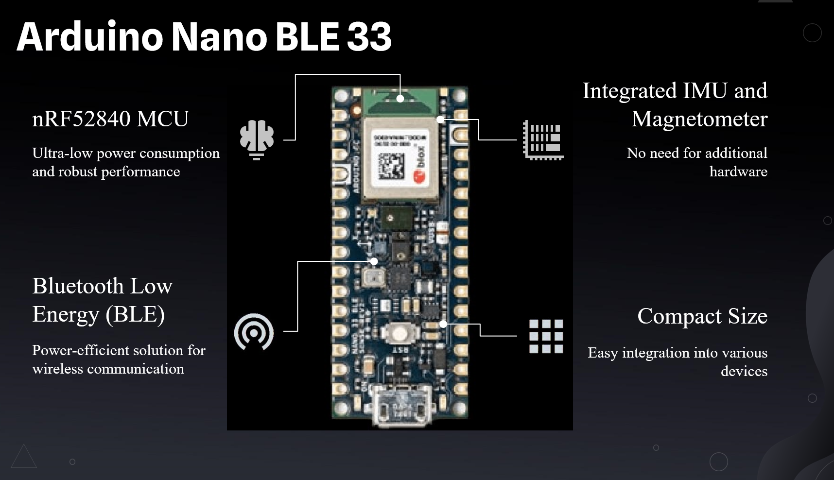
- Microcontroller (Arduino Nano BLE 33 Rev2) Setup
- Sensor Fusion Algorithm Implementation
- BLE Data Transmission Optimization
- Battery Optimization Techniques
- Comprehensive Testing and Debugging
- Sensor Integration:
- Vision System Development & Testing
- Motion Tracking System:
- Camera Calibration and Setup
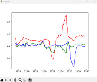
- Marker-based Motion Tracking
- Synchronization with Sensor Data
- Accuracy Validation and Improvement
- Motion Tracking System:
- Software Development
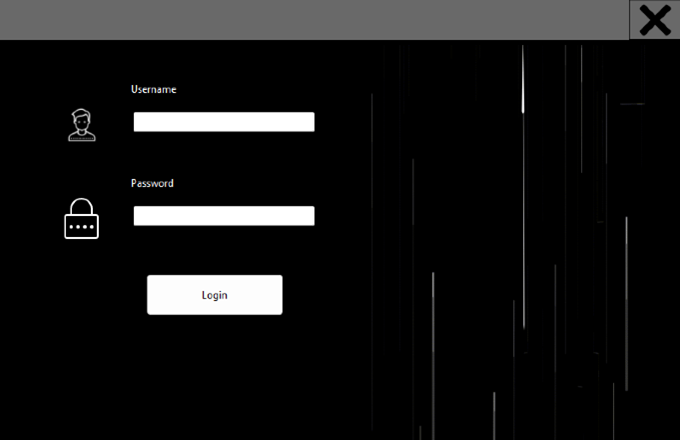
- Therapist Application:
- C# Application Development
- User Interface Design
- Data Visualization and Reporting Tools
- User Testing and Feedback Integration
- Therapist Application:
- Technical Documents
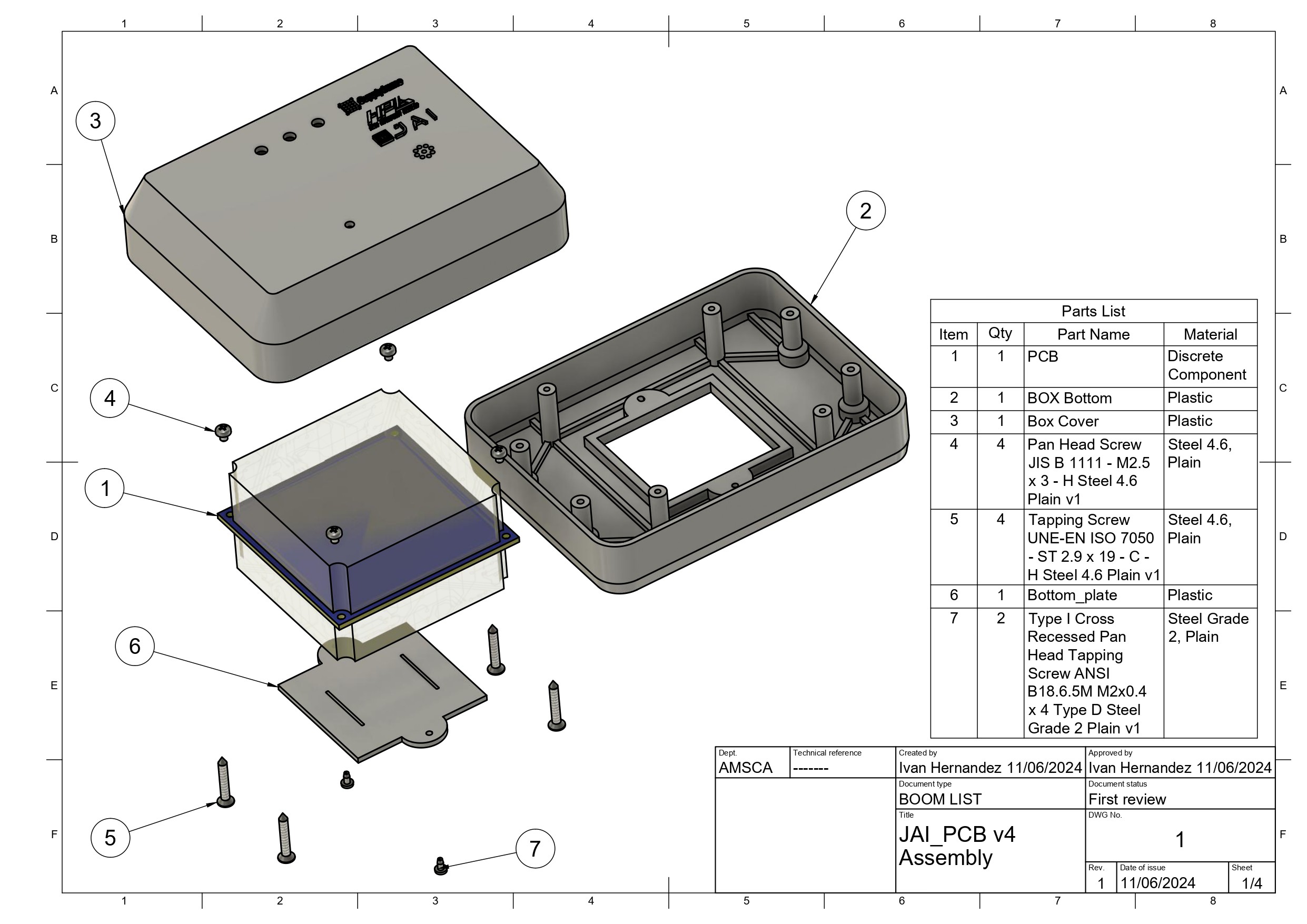
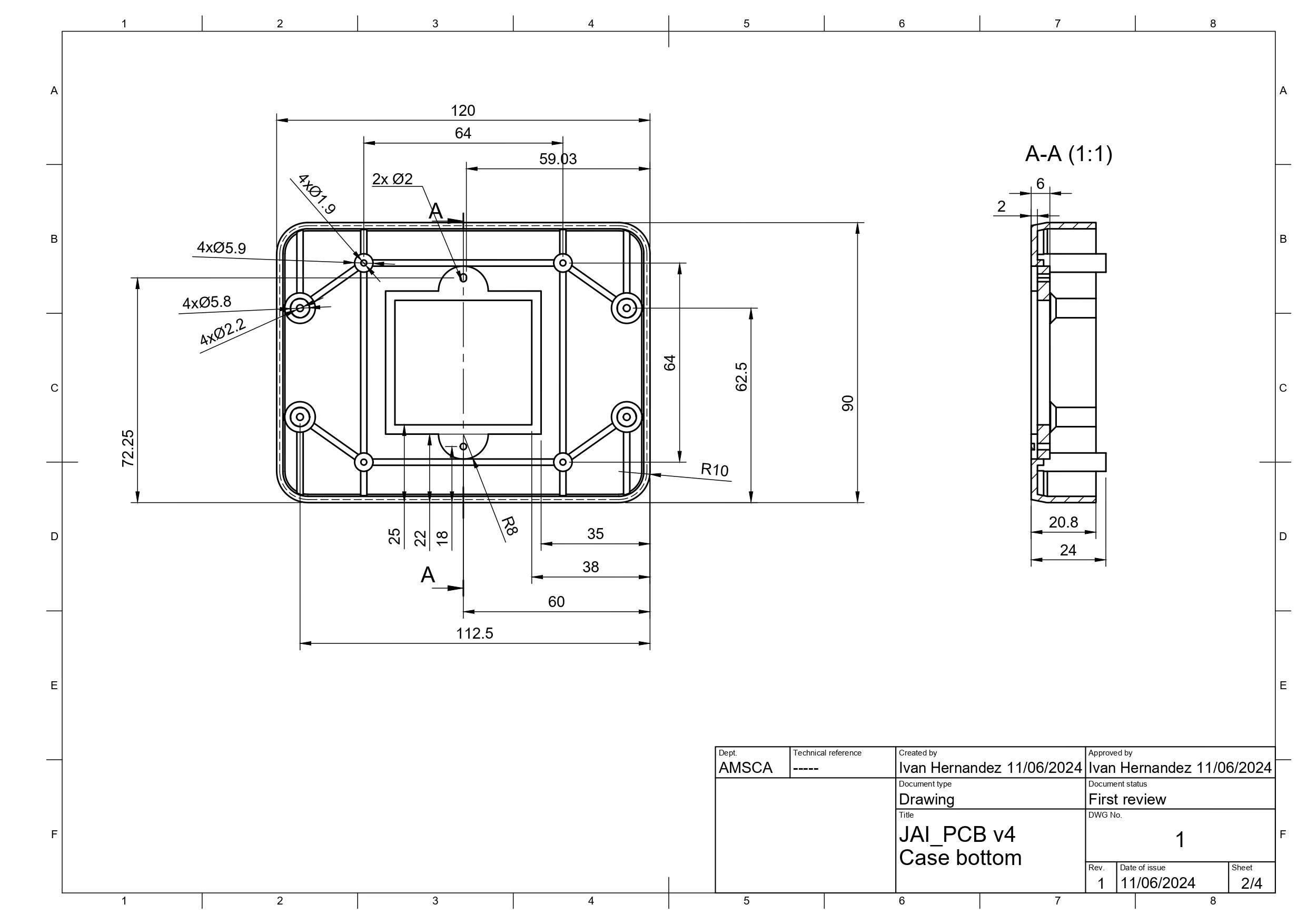
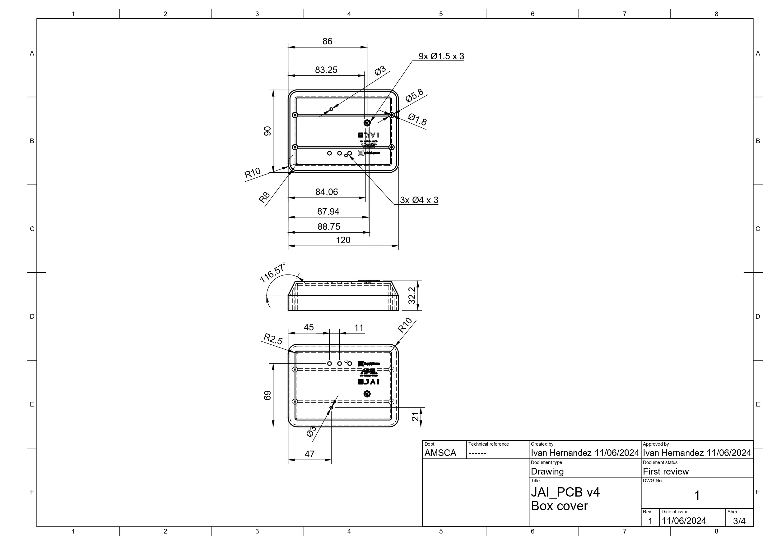
- Bill of Materials (BOM) and drawings
- Software Source Files
Working Principle:
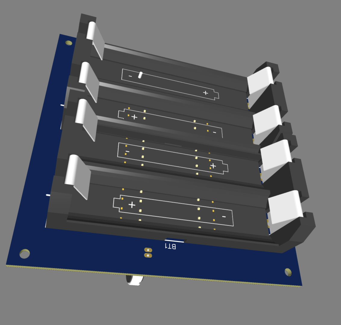
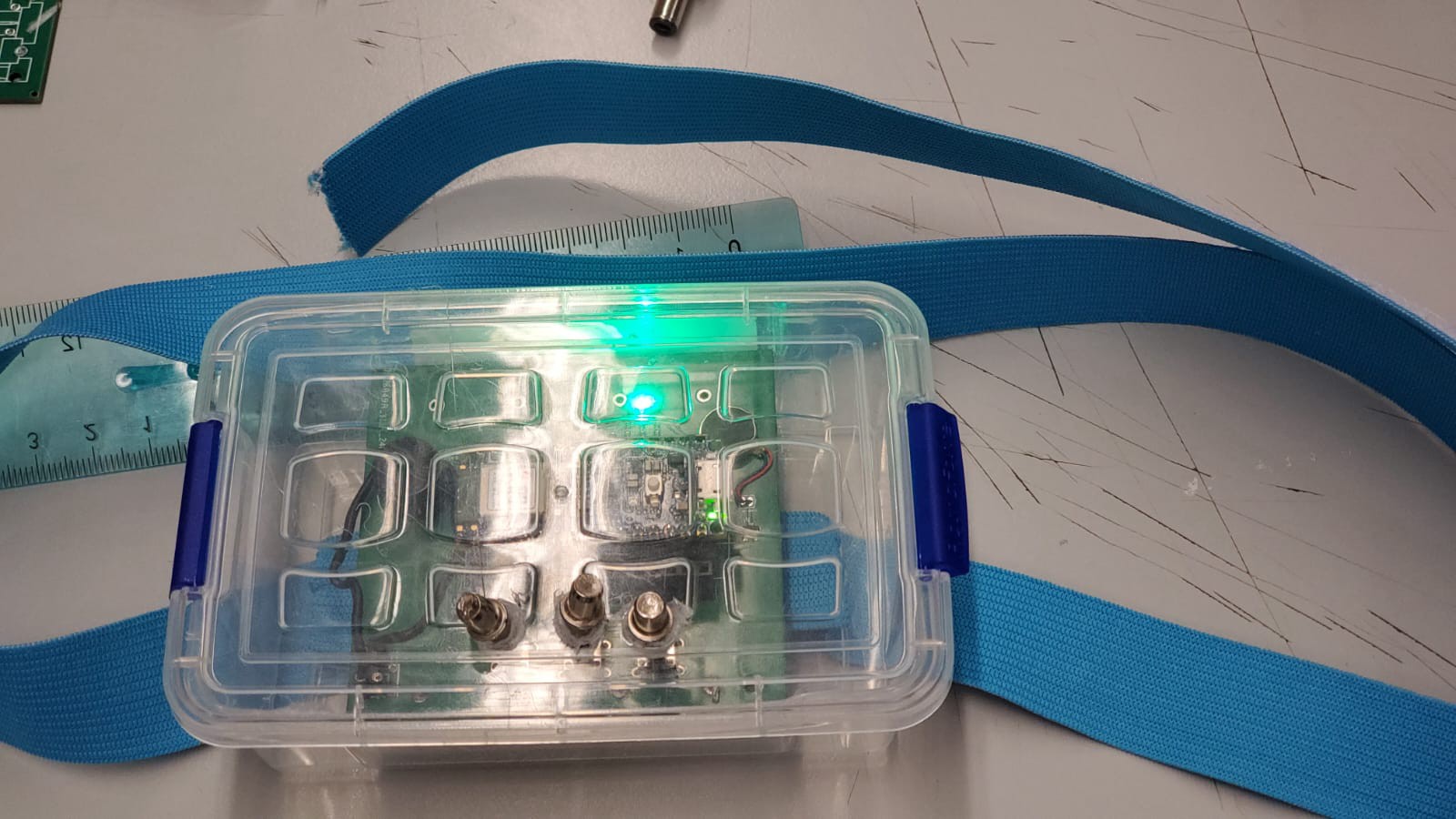
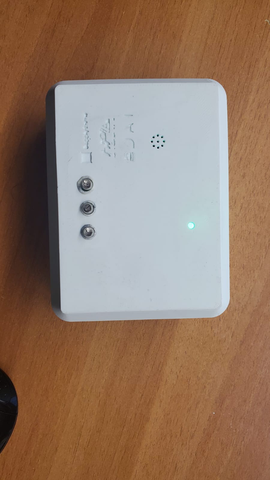
Fig. 1: Equilibrium Evaluation Node
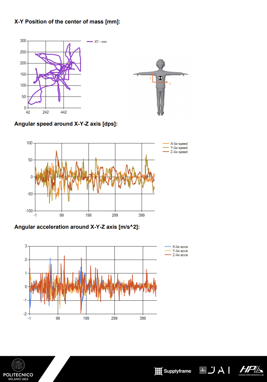
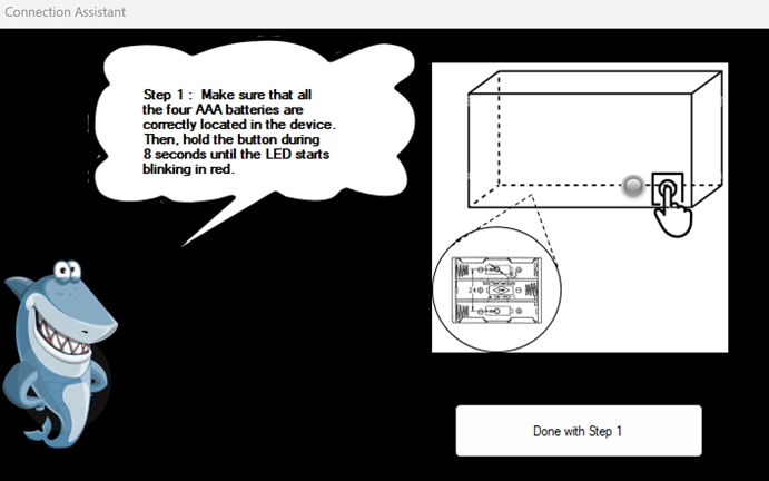
This stand-alone equilibrium evaluation node uses mems IMU sensor to monitor and analyze patient movements during therapy sessions. The core functionality is based on the precise measurement of acceleration, angular velocity, and magnetic fields, provided by integrated sensors.

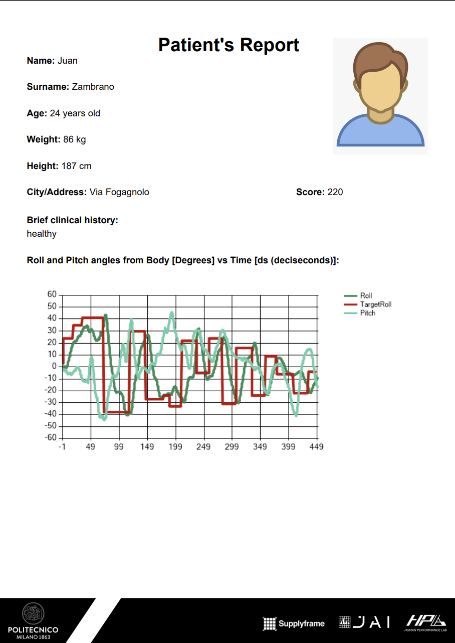
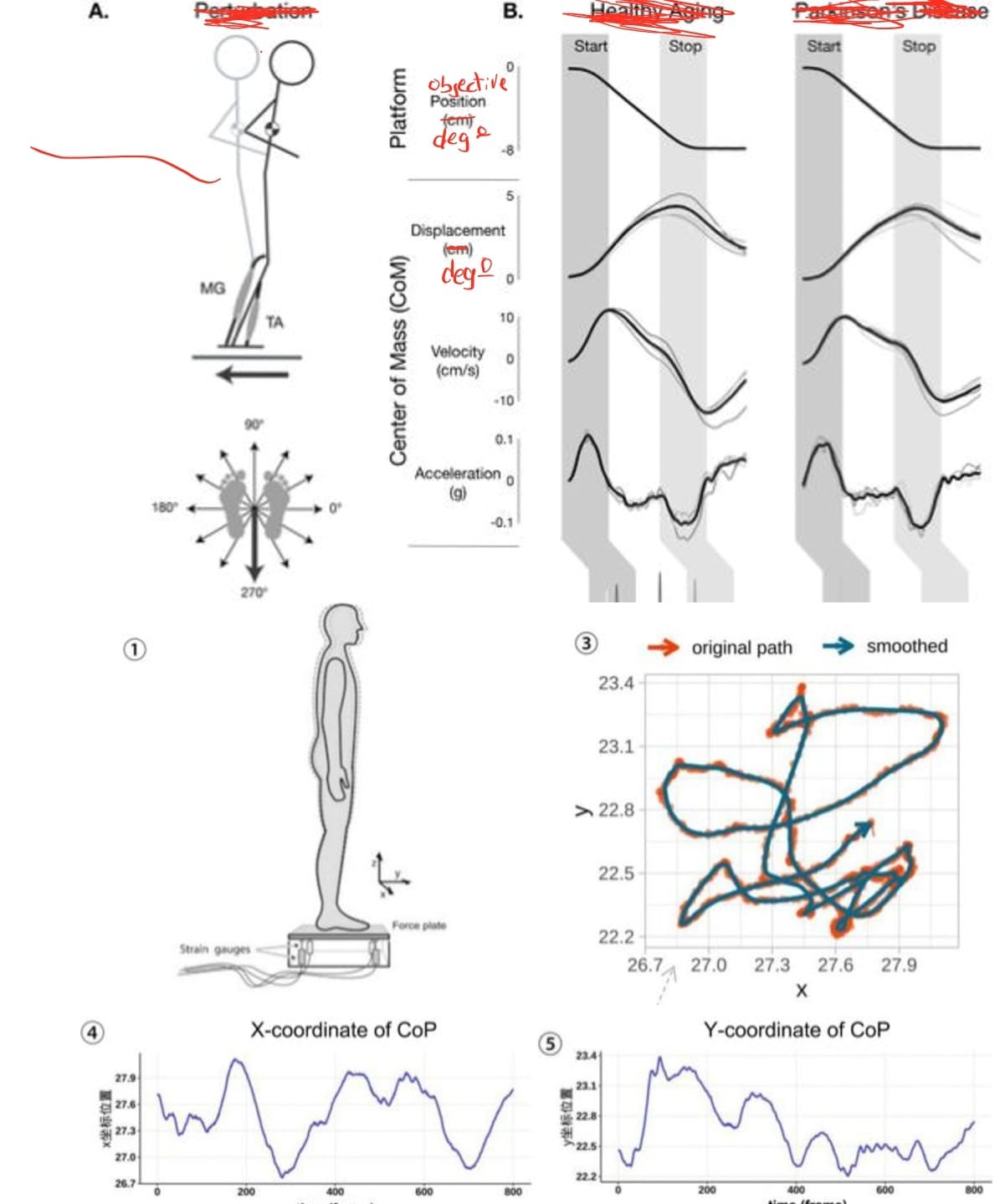
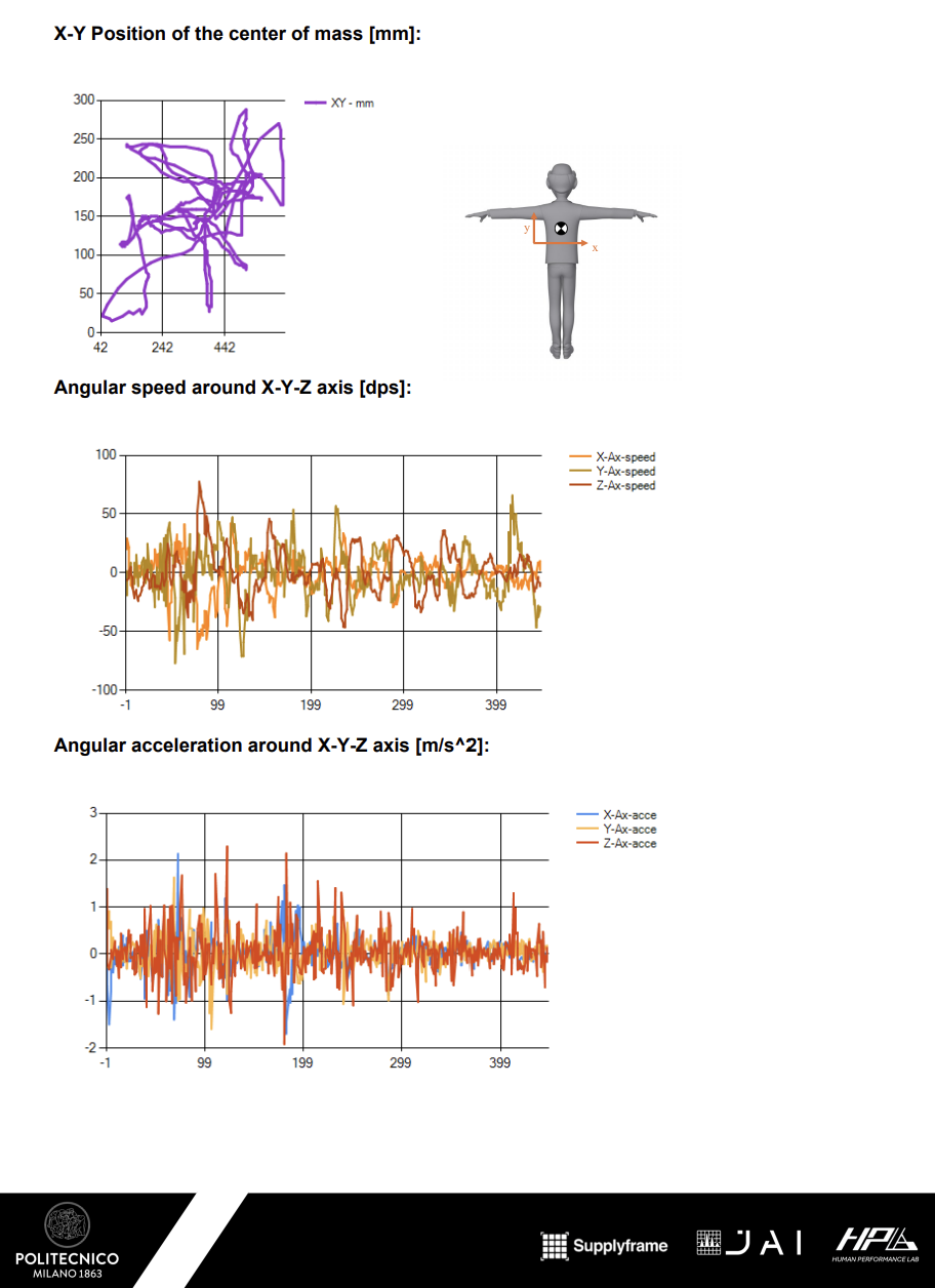
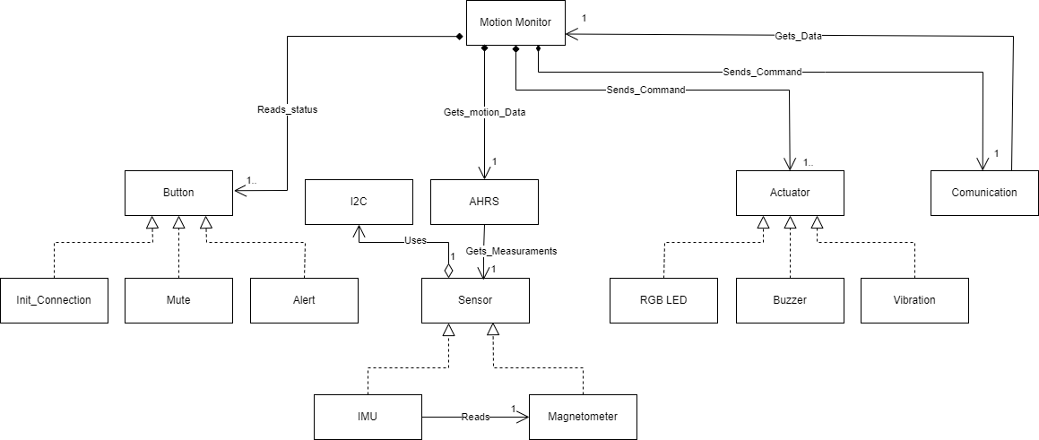
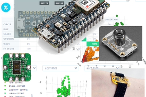
Fig. 2: Sensor Data Fusion and Analysis
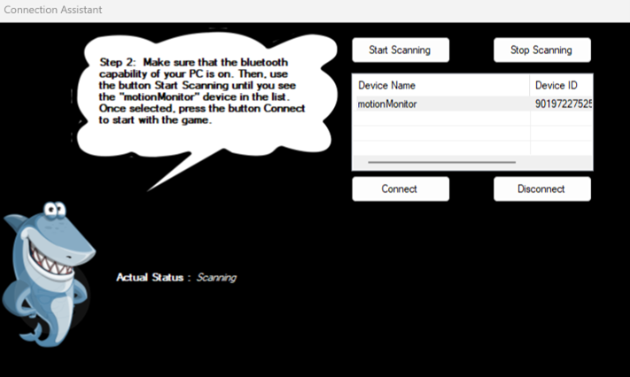
The key working principle involves the fusion of data from the BMI270 and BMI150 sensors using the Madgwick filter, which improves orientation estimation. This data, combined with visual motion tracking, provides a comprehensive assessment of the patient's equilibrium.
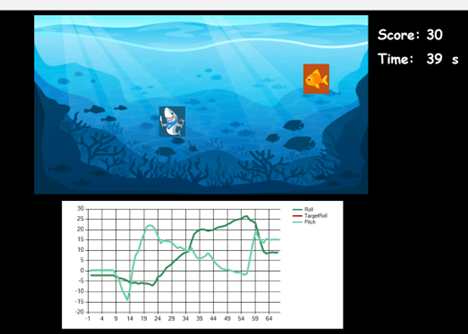
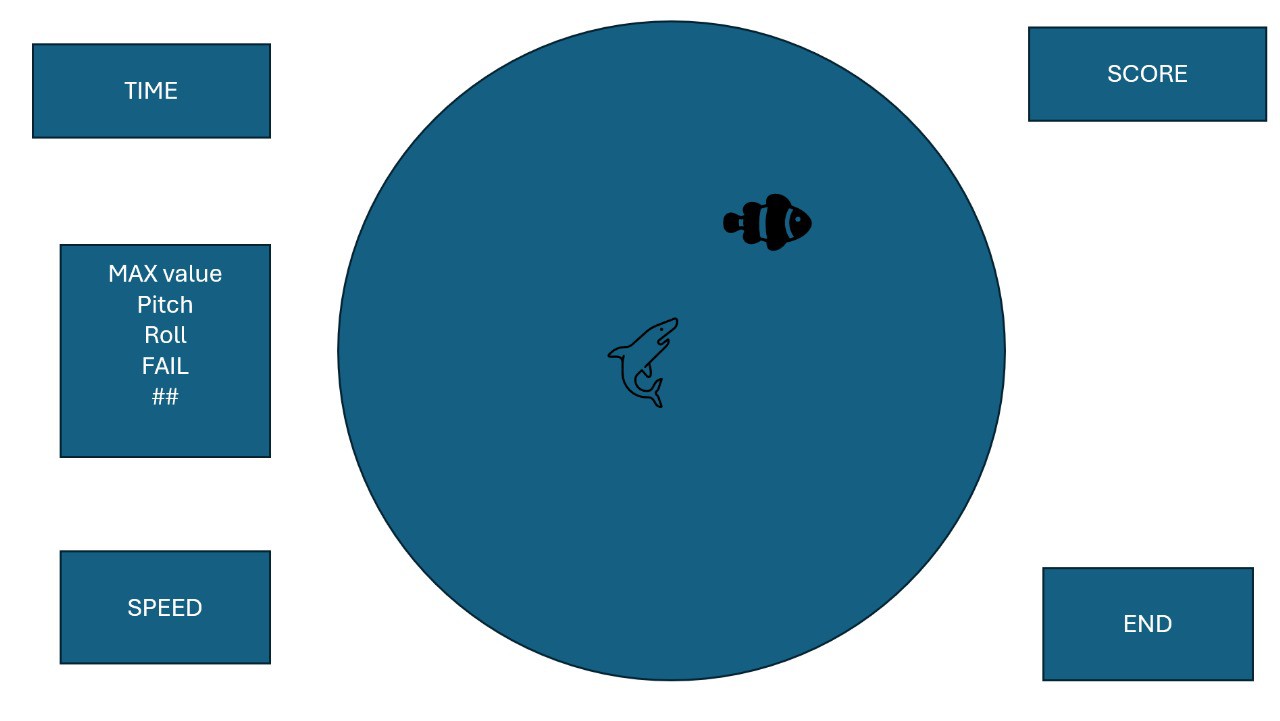
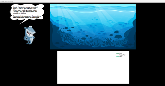
Fig. 3: Real-Time Feedback Mechanism
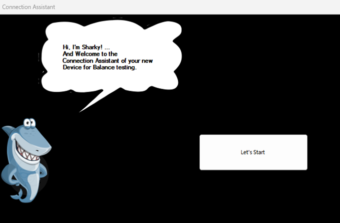
Once motion data is collected, the system provides real-time feedback to therapists via a user-friendly Windows application. This enables immediate adjustments to therapy exercises, enhancing their effectiveness and ensuring patient safety.
Construction:

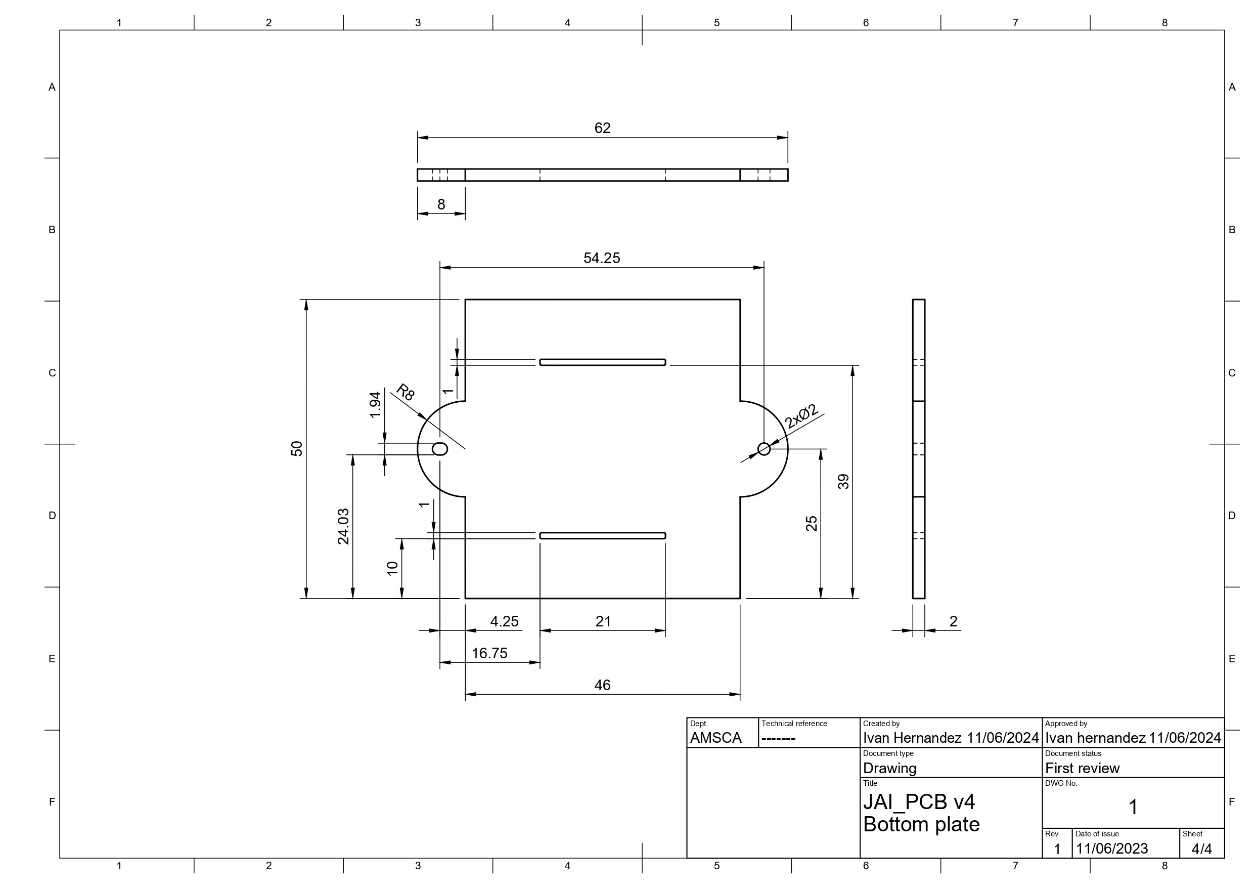
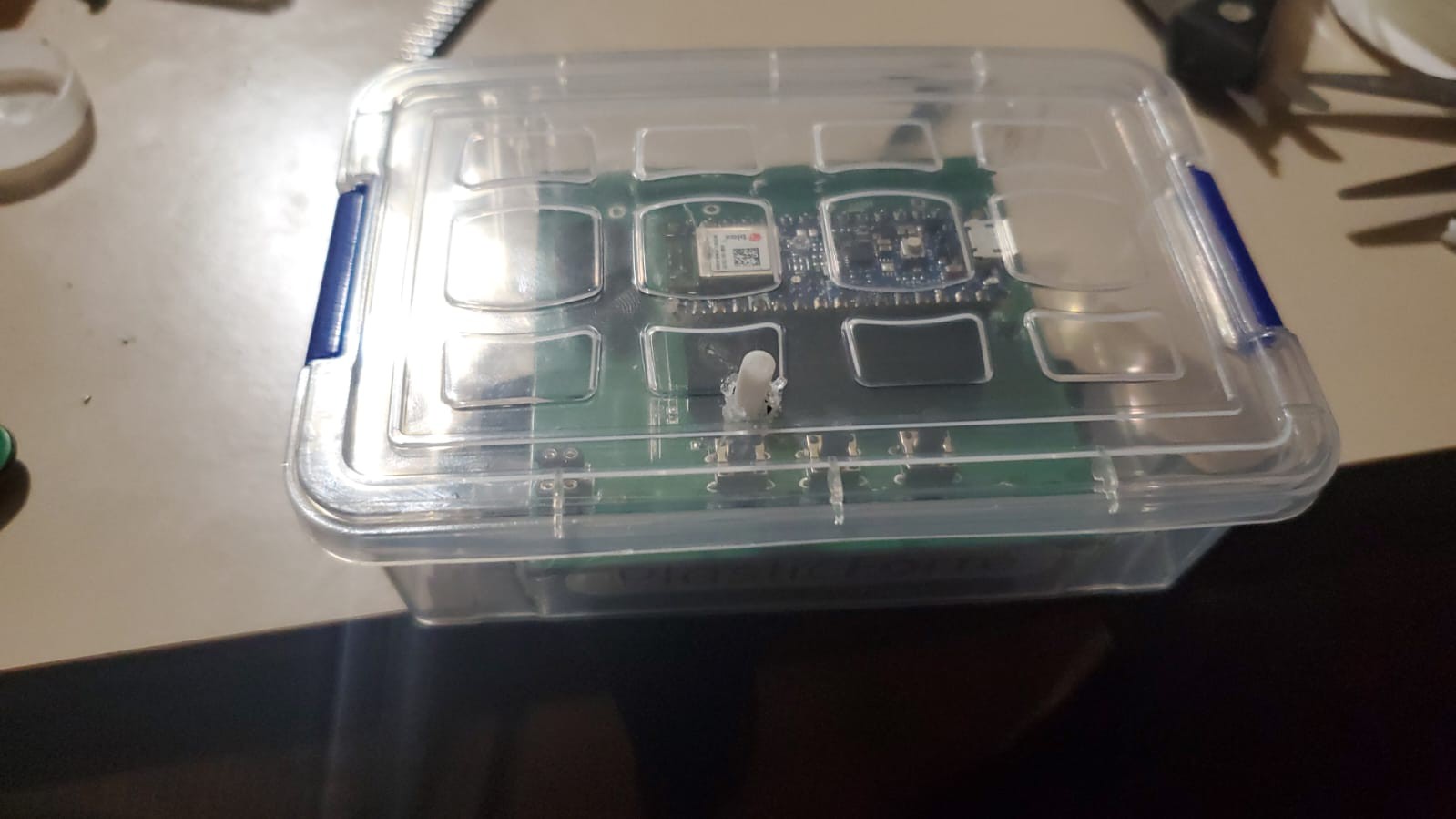
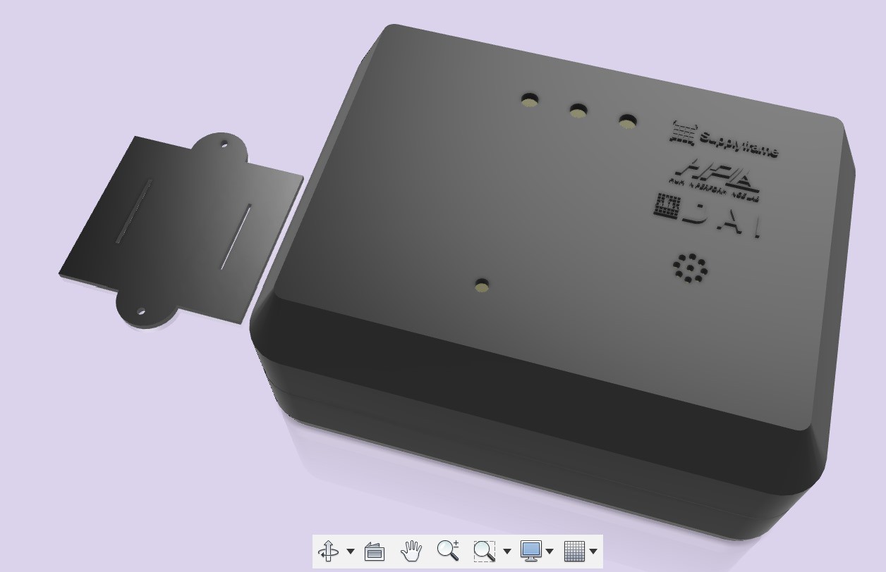
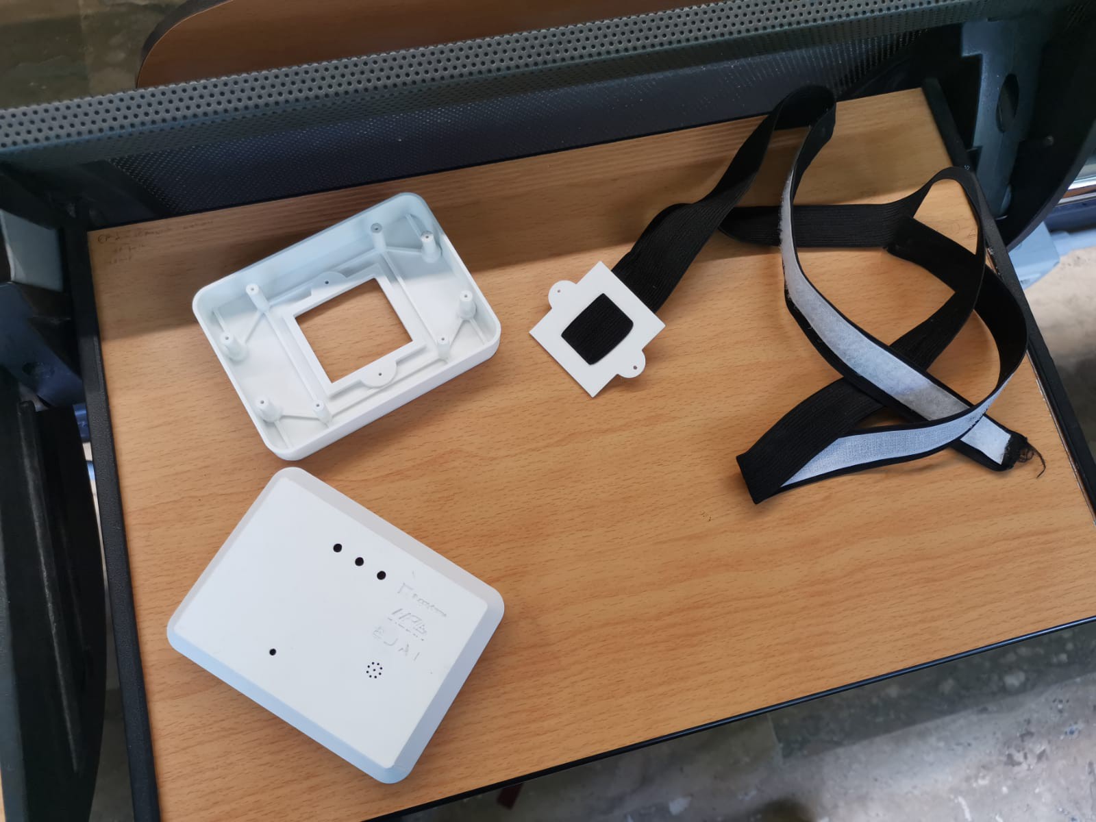
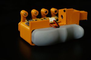
Fig. 4: Prototype Construction
Prototyping involves 3D printing for case. FDM 3D printer technology is used.
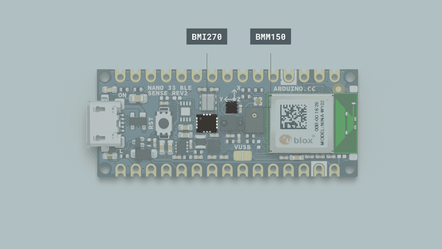
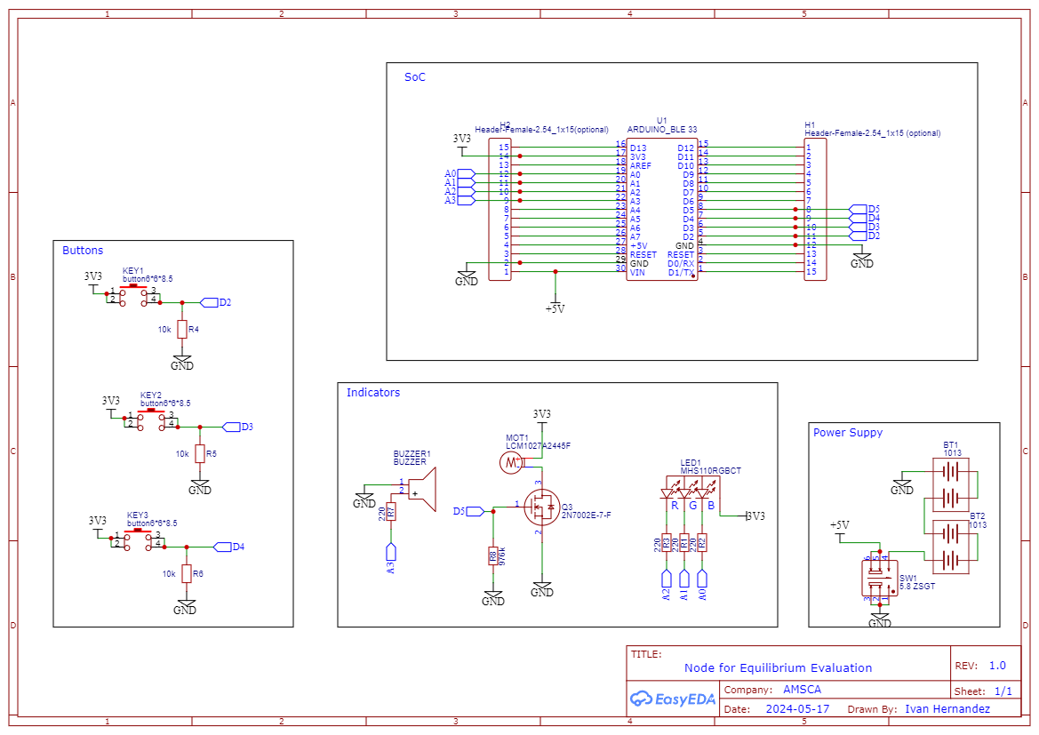
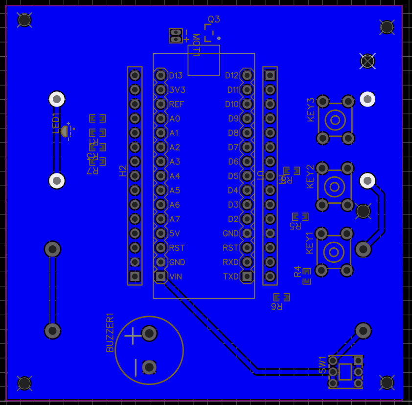
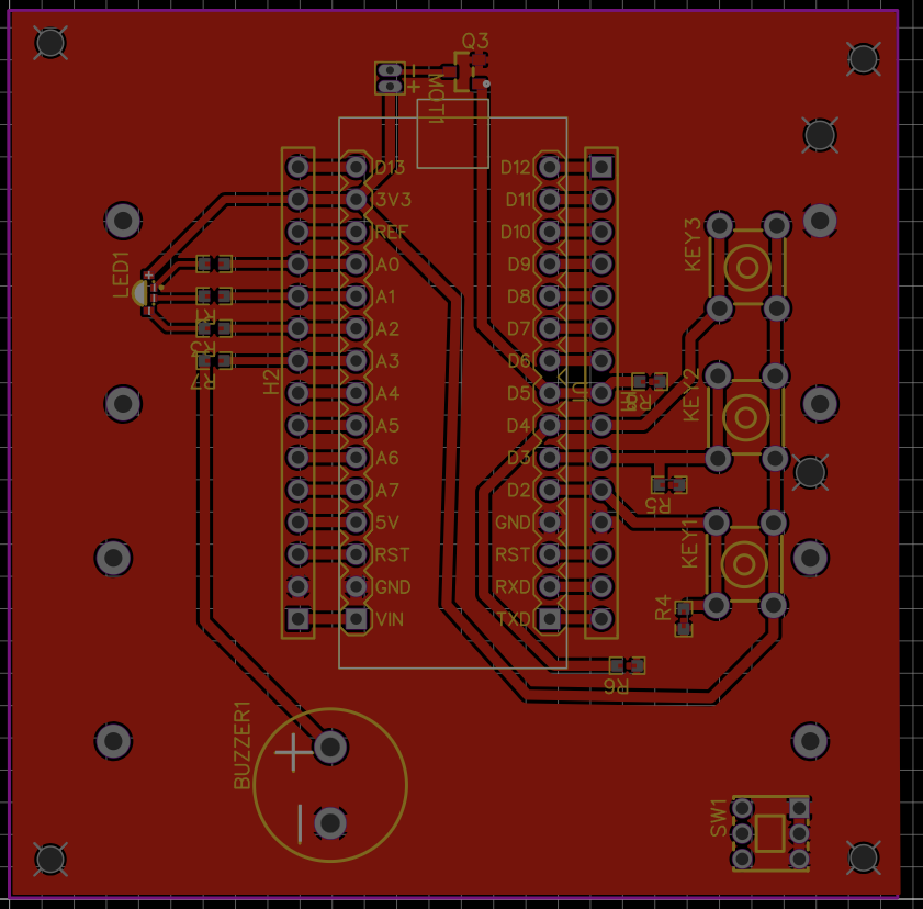
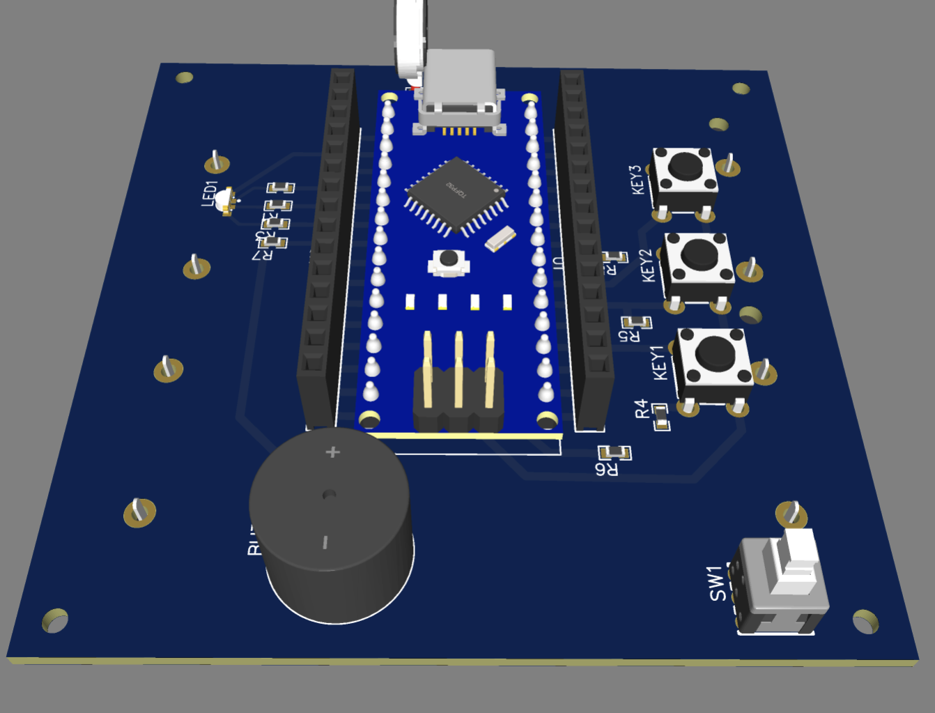
Fig. 5: Sensor Integration
The sensors (BMI270 and BMI150) are integrated into the Arduino Board, designed for compact and efficient placement. The Arduino Nano BLE 33 Rev2 microcontroller manages data processing and wireless transmission.

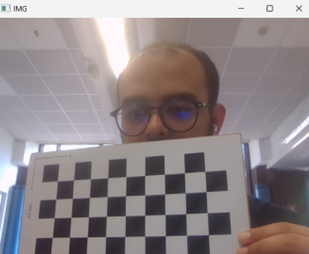
Fig. 6: Vision System Setup
A calibrated camera system tracks markers on the patient, providing an independent measurement of movements. This system is synchronized with sensor data to validate accuracy.
Conclusion
The developed equilibrium evaluation node successfully integrates high-precision sensors, an advanced vision system, and real-time data processing to enhance therapy sessions for children. The system provides accurate and reliable measurements, facilitating effective therapy and real-time adjustments.
Recommendations
- Expand Sensor Array: Consider adding more sensors (e.g., force sensors) for additional data points.
- Enhance Data Processing: Implement machine learning algorithms for advanced motion analysis.
- Optimize Power Consumption: Further reduce power usage to extend battery life.
- Increase User Training: Provide comprehensive training materials for therapists.
- Validate in Diverse Settings: Conduct extensive field testing to ensure reliability across various environments.
- Cost Reduction Strategies: Explore bulk purchasing and alternative materials to lower production costs.


 TURFPTAx
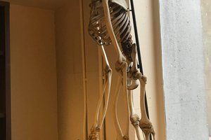
 kzacarian
 EmericB