Matthew James Bellafaire
-
Finally Complete!
02/24/2019 at 17:36 • 0 commentsI think this may have been my longest running project ever. I started this back towards the end of august and its now coming up on march. I wasn't sure at the beginning what this project would require, but I've learned so much about AVRs thanks to all of the code optimization that had to be done over the course of this project. There were times when this project sat on my work bench for a few weeks because I couldn't solve one problem or another, but I found the solution eventually. Either way, its all finished now, here's the final video of the project!:
-
Software Update
01/20/2019 at 23:38 • 0 commentsUntil now I've avoided mentioning software as much as possible, since for the most part it's been in flux throughout this project. This time around, the software is more-or-less complete with some tweaks coming here and there.
the basic format of the code hasn't changed much since last time I talked about it, but here it is:
- take array (used to represent image) from program memory and move it into ram
- take array and split it up into multiple different color arrays
- shift out those color arrays to the anode-side shift registers
- shift the cathode-side shift registers to pulse those LED's on
- repeat 2-4 until a new image is loaded in.
Additionally I created an interrupt subroutine which handles the rotation calculations by interpreting the rotation rate and adjusting the frame display time. Since the matrix divides it's rotation into 5 frames we can take the total time passed between each interrupt and calculate how long it should take to be at that same point again then divide it out to determine each frame's time.
ISR (PCINT1_vect) {
  interruptFlag = true;
}
The interrupt used is shown above, it just flips the interrupt flag which will be handled every time the changeImage() function is called. I had to use the PCINT1 interrupt since the pins for INT0 and INT1 were carelessly used by me when I was creating the PCB.
void changeImage() {
  /*if interruptFlag and a interrupt hasn't been triggered in the last 50ms and PC2 reads a high value */
  if (interruptFlag && micros() > 50000 + lastInterrupt && PINC & (1 << PC2)) {

    interruptFlag = false;

    //we know when the last rotation was and we know when now is
    //so lets make sure the frame displays for the right amount of
    //time for our current speed

    frameDisplayTime =  recalcAnimationTime(lastInterrupt, micros());

    //store again
    lastInterrupt = micros();

  } else {
    interruptFlag = false; //because that was a false positive (probably noise)
  }

  if (micros() > Time + frameDisplayTime) {
    Time = micros();
    currentPositionInArrays++;
    if (currentPositionInArrays >= 5) {
      currentPositionInArrays = 0;
    }

    //move from flash storage to ram
    memcpy_PF(RenderImage, array0[currentPositionInArrays] , 110);

  }
}
the code above only gets called a single time in the main loop of the program. For the most part this is sufficient since I've done a ton of optimizations recently that significantly reduced the execution time of the loop. There is a small drift in the image as a result of this method to handle the interrupt, but I think I’ll leave it as is for now. The interrupt is checked each time it's called and has to meet 2 other conditions if the flag is written true:
- that an interrupt hasn't been handled in the last 50ms
- that PC2 (the pin used to trigger the interrupt) is currently reading high
the first condition is just to eliminate some weird behavior I observed and the second is just to try and make sure the interrupt is executed only when the opto-interrupter is actually detecting the rotation marker. then the frame display time is calculated by the function below and the new time is stored. If all the conditions aren't met however the flag gets written false since it can be assumed the interrupt was premature or just attributable to noise.
unsigned long recalcAnimationTime(unsigned long lastTime, unsigned long currentTime) {
  return (unsigned long)((currentTime - lastTime) / 10);
}
the animation is calculated by this simple function, since everything's timed in microseconds all variables to do with frame time are unsigned longs.
other than these changes the code is more-or-less the same with some bloat removed and comments added. if you have any questions feel free to comment!
that just about wraps up the recent updates to this project, functionally it's done and just needs some animations to make it come alive!
-
Hardware Updates
01/20/2019 at 23:02 • 0 commentsNow we’re back in my realm of competency, so let’s get going! The biggest issue I was encountering in this project was that the image would rotate slowly but never remain stable. With this behavior it would have been impossible to display 3D animations, which was the ultimate goal of this project. To eliminate this problem two hardware changes had to be made, and both of those are feedback.
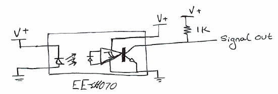
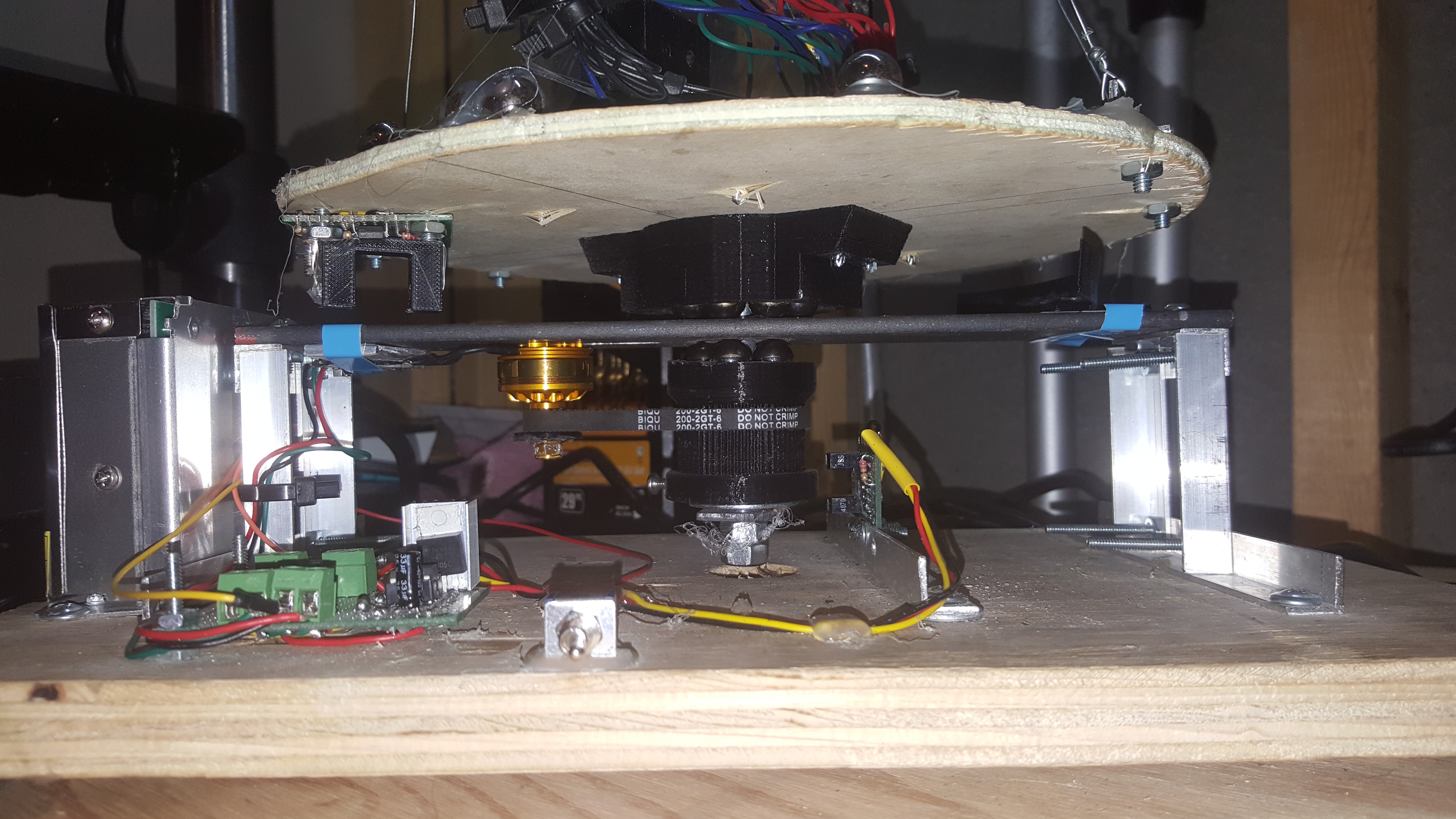
Previously I had used a crude feedback system on the motor controller that would give the ATtiny85 controlling the ESC some information about how fast it was spinning. As to why I had to do that given that I’m using a brushless motor with an ESC is a whole other issue. However, previously the feedback was accomplished by a limit switch which would be pressed every time a rotation had been complete. This solution worked but was far from ideal, there were significant wear issues with the arrangement and I ended up replacing the limit switch twice. Now the motor gets its feedback from a more useful opto-interrupter circuit, since the main gear and this opto-interrupter never come in contact they should never wear out. The opto-interrupt in question is the EE-SX4070, which had a sufficiently wide opening to be useful for my application. The schematic used for the entire sensor module is fairly simple (shown below). Whenever the opto-interrupter is triggered it sends a high signal to the ATtiny85 which is counted and used to measure/adjust the speed of the motor.
![]()
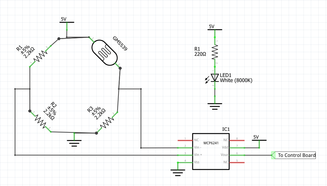
For the spinning portion of the project however I had to be more creative. Since the top part still has some wobble to it (about 3mm of play) the EE-SX4070 (with it's 8mm deep slot) was the more difficult option for that portion since putting something in to trigger it could easily end up with it being destroyed. Because of that issue I decided to just make my own opto-interrupter, for this I utilized what I had on hand:
![]()
I used some 2.2k resistors, a GM5539 Photo-resistor, and a MCP6241 rail-to-rail opamp. The resistors and photoresistor create a wheat-stone bridge which when lit creates a voltage potential across the bridge (left center being ground on my multimeter) of -.9v, when the LED is blocked the potential goes to about 1.2v. For this circuit the opamp is just used as a comparator, but it does its job nicely. Whenever the light from the LED is blocked a 5v signal is sent out to the matrix driver board and when it is unblocked the out-line goes to 0v. The main advantage to doing this myself was that I could create a wide and tall component to the exact size requirements I needed. The body of the part was modeled in google SketchUp and 3d printed, all components were then built onto protoboard then the power, ground, and signal wires were bodged into the main board. Which isn't ideal, especially because I originally planned to have this as an option but failed to leave any pads on the PCB to accommodate it.
![]()
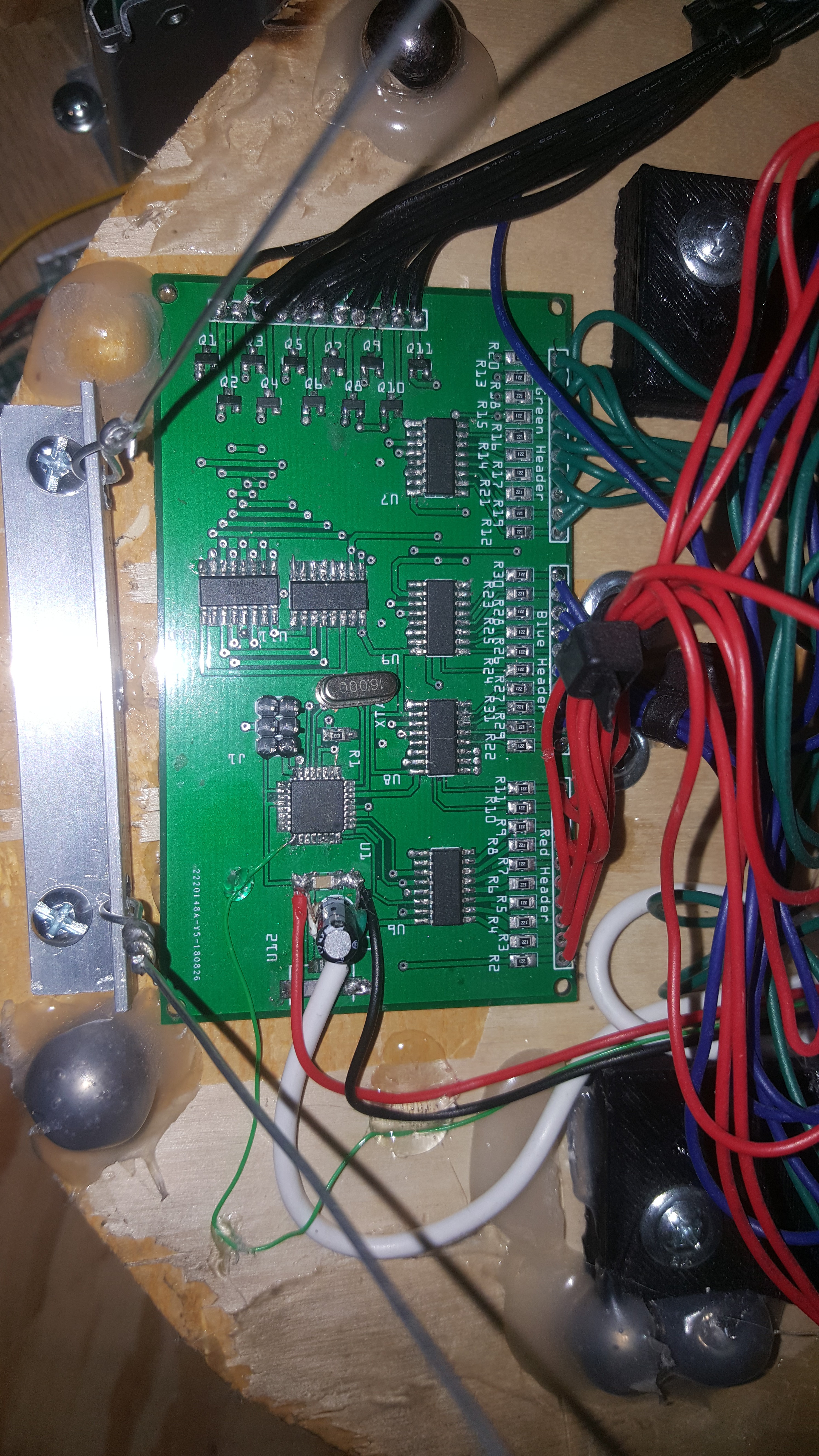
Custom Opto-interrupter installed on main platform (upper left) ![]()
bodge wires on main board, green wire for signal. -
Mechanical Updates
01/20/2019 at 22:08 • 0 commentsI don’t think I can say this enough, I’m a computer engineering student currently and mechanical design has never been a strong suit for me. With that said, I for some reason decided to design every part of the mechanical system myself (including the bearings). Hindsight is 20/20 on this one and I don’t think I’ll attempt the same thing without thoroughly thinking it through first but here we go.
Previously there were three key issues with the mechanical elements of the display:
- The display image would shake back and forth due to poor support of the LED matrix itself
- The main plate which supported the display would warp and bend exasperating the first issue
- The entire project would move across the surface it rested on.
For the first issue the solution was simple, add some supports. However, due to the nature of the display, having too large a support would result in it being visible to the viewer. Previously I attempted to deal with this by tensioning the corners with fishing line, but that did little to resolve the issue due to the line’s elasticity. I chose to use something stronger, in this case picture wire. The wire is significantly stronger than the fishing line, however, it required more modification and is much more visible. To use the wire, I had to make two aluminum ties down points, otherwise the wire might tear through the wood disk the matrix rides on. All and all, this works alright and isn’t visible when the display is spinning too much, but it could be better.
![]()
For the second issue there really was an easy solution, the aluminum plate just had too much give to it and couldn’t support the project properly. The solution was to stop using aluminum. Previously the main riding surface was 3mm thick 2” wide aluminum bar, that has been upgraded to 5mm thick 2” wide steel bar. The difference is night and day and the entire project works much better than it did previously.
![]()
The final issue was just caused by poor balance of the rotating section, I’ve done all I can think of to balance it properly (don’t laugh at my hot-glued ball bearings!). This was corrected by two changes, firstly adding rubber feet, which should have been done from the start, but I never ordered any. The second change was to reduce the rotation speed to the minimum that would still produce a decent image. In the case of the second change the rotation speed was reduced from 16 rev/sec to 7 rev/sec and could potentially go lower at the cost of quality. I’ll cover how I know the rotation rate in the next log, hardware!
-
Multiple Updates Incoming
01/20/2019 at 21:45 • 0 commentsI lost some interest in this project for a little while (mostly because I had another one that seemed more interesting at the time) but I'm back! there were some small hurdles to overcome here and a lot of larger ones. From the last log I've taken the checklist of things to complete and crossed off all of them that have been achieved:
- I
mprove image changing in control board program to allow for true 3D animations - because of above item, improve java program to write code for new structure to allow for easy animation making
- I
ncrease diffusion of LED's to make them more visible during rotation improve starting and speed stability of mechanical partsimprove mechanical stability of matrixif speed stability cannot be improved, add feedback to control board to prevent the image from drifting.
So... yeah, a lot happened, as a result this log is going to be split up into 4 logs with the other logs covering the mechanical, hardware, and software changes that have been made to the project.
Anyone who's been reading through this project from the beginning knows that I've already created a java program that simplifies the animation making. Suffice it to say the micro controllers code has changed so drastically that the original one will just have to be scrapped.
But with all that said, here is the circle test demo used before recreated on the project with the new modifications:
a lot of flashing in this video, so heads up now, also the video is somewhat loud compared to where the project was last month, there is a lot of improvement. See you in the following logs!
- I
-
Getting into the Home Stretch
10/23/2018 at 02:00 • 0 commentstwo logs ago I wrote about a few challenges that were on the horizon to bring this project into a stage close to completion. Most of them centered around performance improvements and making the system more "predictable". Most of those goals have now been achieved. The micro-controller board has been sped up to what I now think is the absolute limit without rewriting the methods and the mechanical side now has more stability in both structure and speed.
But what was the purpose of these goals? before adding these improvements there wasn't a whole lot of precision in the display. A single image could only be drawn then rotated, making most of the resulting images look crude and bland since they were all just a compilation of circles. With the improvements to the control board images can be changed down to the microsecond. with the improvements to the motor control board the speed is now a fixed RPM allowing for predictable rotation and no need for rotation monitoring by the main control board (though it might be worth adding). It is now possible to control the 3D image in almost all dimensions. Each rotation gets about 10 image changes. This means that in addition to the 110 RGB LEDs that can be lit the matrix now has 10 different "radial" images that can be displayed (kind of like a 10-slice pizza). The video below illustrates this very well, the circle in the center is displayed on only one "radial" and thus appears as a nearly flat image.
Warning about video, somewhat loud and lots of flashing lights just letting you know just in case that's a problem for you.
with all these improvements the project is in its final stage, however there are a few things that need improvement. In the demonstration above there are 10 images that are being switched out to constantly, these are in a fixed loop because each rotation takes about .06 seconds. The result of the speed of rotation and the current structure of the program is that to create just two still images that interchange with each other every second would take almost 330 arrays which is nearly double the current capability. One definite requirement going forward is to restructure the program to make the still images easier to handle. In addition the image currently drifts due to small variations in the speed of the driving motor. this is a pretty cool effect on a single image but i feel as though it would become a much bigger issue going forward if the patterns were more complex. There are two ways that I think this can be resolved, either by ensuring an absolutely constant speed from the motor or by adding some rotational feedback.Another change to make to this has to do with the matrix itself, images look somewhat crude with the LED's so spaced out. I'd like to make their light spread a bit more, this is probably going to require some kind of covering over each LED but I’m not sure how to accomplish this yet.
The mechanical parts of this project could use a bit of work also, you can see in the video that I had to give the display a bit of a push start before it would spin. Although it's very close to starting up on its own (and it does sometimes) it has quite a bit of resistance to overcome in the beginning, this should be reduced. The physical stability of the matrix should also be dealt with, the matrix sways by about 2cm at the very top, leading to an image distortion that is visible in the video when the flat image is viewed completely from the side.
So, then it's improvement list time:
- Improve image changing in control board program to allow for true 3D animations
- because of above item, improve java program to write code for new structure to allow for easy animation making
- increase diffusion of LED's to make them more visible during rotation
- improve starting and speed stability of mechanical parts
- improve mechanical stability of matrix
- if speed stability cannot be improved, add feedback to control board to prevent the image from drifting.
-
take the hard path when you only have to take it once
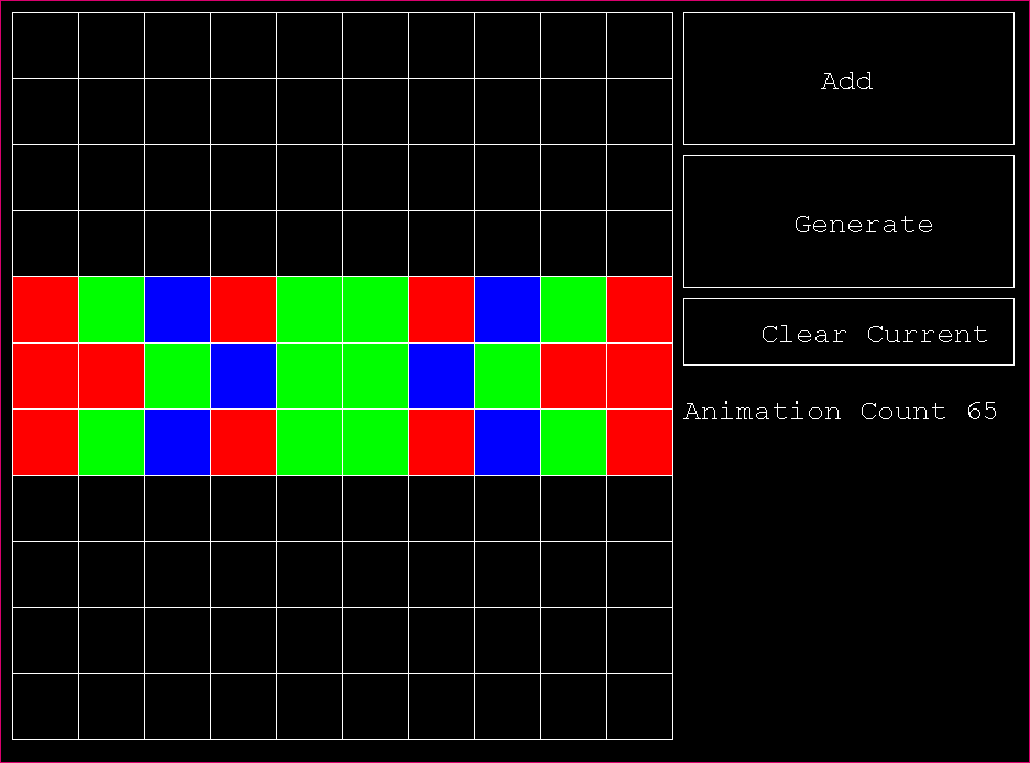
10/15/2018 at 21:47 • 0 commentsI think this might have started as a bit of a joke to myself "well I don't want to make all those patterns for the matrix, might as well have a program do it for me". Regardless, it happened anyway after about 4 hours of work in NetBeans I now have a decent AWT matrix array generator that works.
![]()
So yeah, that happened... but I’m glad I bothered to make this, it's incredibly easy now to generate the arrays that control the images. this whole project runs on byte arrays that operate essentially as "Frames", so this tool gives me the ability to program more complex animations and make them look better. Tedious things are no fun and messing with a bunch of conditional statements and manually editing the values in the arrays would have taken me equally as long for a decent animation as this tool did (and it would have been way less fun). I'll have the java source code attached to this project, in addition to the end of this log (I don't feel comfortable downloading an antonymous jar file and I don't expect you to be either). The only reason this whole thing was written using AWT was that it's something I’m familiar with thanks to all the time spent in high school making java games. The program essentially just has a grid of boxes, when you click a box it changes color in the order black>red>green>blue. Hitting "Add" will have that frame included in the output, "clear current" just changes all the boxes back to black. Hitting "Generate" takes all the images that were made and writes the code for them then dumps that into a text file which still must be manually copied and pasted into the sketch. "Animation count" just keeps track of the number of arrays created.
Now, on the Arduino side of things a few changes have been made. Whereas before the board would store all the arrays in ram they are now kept directly in the flash memory. This was achieved by utilizing the pgmspace.h library, which allowed me to keep all the byte arrays in flash memory and then read from them at will. making this change has opened the capability of this project by quite a bit. Now using the matrix generator and the new structure for the arrays the ATmega on the board can store about 180 byte arrays with 110 values each. which is a significant upgrade from the previous ~10 or so.
![]()
At this point I'm glad I chose the ATmega328 for this project, sure a better micro-controller with more speed and more memory would have made this whole project go a lot faster, but it wouldn't have been this fun. I've learned a lot so far just trying to pull every gram of performance out of this $3 chip and let me say it's been a fun challenge every step of the way. see you in the next log! (also feel free to use this code however you want)
package matrixarraygenerator;

import java.awt.Color;
import java.awt.Font;
import java.awt.Graphics;
import java.awt.event.KeyEvent;
import java.awt.event.KeyListener;
import java.awt.event.MouseAdapter;
import java.awt.event.MouseEvent;
import java.io.File;
import java.io.FileWriter;
import java.io.IOException;
import java.util.logging.Level;
import java.util.logging.Logger;
import javax.swing.JFrame;
import javax.swing.JPanel;

/**
 *
 * @author James
 */
public class MatrixArrayGenerator extends JPanel {

    public static int squareWidth = 60;
    public static int squareHeight = 60;
    public static int gridRightBound = 10 + (10 * squareWidth);
    public static int outputFileCount = 1;

    static File outputFile;
    static FileWriter outputWriter;
    static boolean writeflag = false;

    public static int[] currentArray
            = {0, 0, 0, 0, 0, 0, 0, 0, 0, 0,
                0, 0, 0, 0, 0, 0, 0, 0, 0, 0,
                0, 0, 0, 0, 0, 0, 0, 0, 0, 0,
                0, 0, 0, 0, 0, 0, 0, 0, 0, 0,
                0, 0, 0, 0, 0, 0, 0, 0, 0, 0,
                0, 0, 0, 0, 0, 0, 0, 0, 0, 0,
                0, 0, 0, 0, 0, 0, 0, 0, 0, 0,
                0, 0, 0, 0, 0, 0, 0, 0, 0, 0,
                0, 0, 0, 0, 0, 0, 0, 0, 0, 0,
                0, 0, 0, 0, 0, 0, 0, 0, 0, 0,
                0, 0, 0, 0, 0, 0, 0, 0, 0, 0
            };

    //look, its not a professional piece of software, i'm probably never going to touch it again after this project. i don't care how much memory it eats.
    public static int[][] savedArrays = new int[110][1000];
    public static int savedArrayIndex = 0;

    public void mouseClicked(MouseEvent e) throws IOException {
        int x = e.getX();
        int y = e.getY();
        System.out.println(x + "," + y);//these co-ords are relative to the component

        if (clickedButton(x, y) < 110) {
            currentArray[clickedButton(x, y)] = 1;
        }
    }

    public static int clickedButton(int x, int y) throws IOException {
        for (int a = 0; a < 10; a++) {
            for (int b = 0; b < 11; b++) {
                if (x < 10 + squareWidth * (a + 1) && x > 10 + squareWidth * (a) && y > 35 + squareHeight * b && y < 35 + squareHeight * (b + 1)) {
                    return a + b * 10;
                }
            }
        }
        if (x > 10 + gridRightBound && x < 10 + 300 + gridRightBound && y > 35 && y < 160) {
            add();
            return 110;
        }
        if (x > 10 + gridRightBound && x < 310 + gridRightBound && y > 170 && y < 290) {
            writeflag = true;
            generate();
            writeflag = false;
        }
        if (x > 10 + gridRightBound && x < 310 + gridRightBound && y > 300 && y < 360) {
            clear();
        }
        return 120;
    }

    public static void clear() {
        for (int a = 0; a < 110; a++) {
            currentArray[a] = 0;
        }
    }

    public static void generate() throws IOException {
        outputFile = new File("Generated Matrix Array" + outputFileCount + ".txt");
        outputFileCount++;
        outputWriter = new FileWriter(outputFile, false);
        String output = "//Generated Arrays created in MatrixArrayGenerator by james bellafaire\n";
        for (int a = 0; a < savedArrayIndex; a++) {
            output = output + "const PROGMEM byte array" + a + "[] = {";
            for (int b = 0; b < 110; b++) {
                output = output + savedArrays[b][a];
                if (b != 109) {
                    output = output + ", ";
                }
            }
            output = output + "};\n";
        }
        output = output + "\n\n\n//generated array coppying created in MatrixArrayGenerator by james bellafaire\n void changeImage() {\n  if (millis() > Time + animationDisplayTime) {\n"
                + "    Time = millis();\n";
        output = output + "if (animationCount == 0) {\n"
                + "      memcpy_PF(RenderImage," + "array0" + ", 110);\n"
                + "      animationCount++;\n"
                + "    }";
        for (int a = 1; a < savedArrayIndex; a++) {
            output = output + " else if (animationCount == " + a + ") {\n"
                    + "      memcpy_PF(RenderImage, array" + a + ", 110);\n"
                    + "      animationCount++;\n"
                    + "    }";
        }
        output = output + "if (animationCount == " + (savedArrayIndex) + "){ animationCount = 0;}\n}\n}";
        outputWriter.write(output);
        outputWriter.close();
    }

    public static void add() {
        for (int a = 0; a < 110; a++) {
            savedArrays[a][savedArrayIndex] = currentArray[a];
        }
        savedArrayIndex++;
    }

    public static void main(String[] args) throws InterruptedException, IOException {
        //well i gotta get the data out somehow
        JFrame frame = new JFrame("matrix generator tool");
        MatrixArrayGenerator pane = new MatrixArrayGenerator();
        frame.add(pane);
        frame.setSize(940, 720);
        pane.setBackground(Color.black);
        frame.setLocationRelativeTo(null);
        frame.setVisible(true);
        frame.setResizable(false);
        frame.addMouseListener(new MouseAdapter() {// provides empty implementation of all
            // MouseListener`s methods, allowing us to
            // override only those which interests us
            public void mousePressed(MouseEvent e) {
                int x = e.getX();
                int y = e.getY();
                try {
                    //                System.out.println(e.getX() + "," + e.getY());
//                System.out.println(clickedButton(x, y));
                    if (clickedButton(x, y) < 110) {
                        switch (currentArray[clickedButton(x, y)]) {
                            case 0:
                                currentArray[clickedButton(x, y)] = 1;
                                break;
                            case 1:
                                currentArray[clickedButton(x, y)] = 2;
                                break;
                            case 2:
                                currentArray[clickedButton(x, y)] = 3;
                                break;
                            case 3:
                                currentArray[clickedButton(x, y)] = 0;
                                break;
                            default:
                                break;
                        }

                    }
                } catch (IOException ex) {
                    Logger.getLogger(MatrixArrayGenerator.class.getName()).log(Level.SEVERE, null, ex);
                }
            }
        });
        frame.setDefaultCloseOperation(JFrame.EXIT_ON_CLOSE);
        while (true) {
            pane.repaint();
        }
    }

    public MatrixArrayGenerator() {
        setFocusable(true);
    }

    @Override
    public void paint(Graphics g) {
        super.paint(g);
        g.setColor(Color.white);

        //draw grid lines
        for (int a = 0; a < 11; a++) {
            g.drawLine(10 + (a * squareWidth), 10, 10 + (a * squareWidth), 10 + 11 * squareHeight);
        }
        for (int a = 0; a < 12; a++) {
            g.drawLine(10, 10 + a * squareHeight, 10 + squareWidth * 10, 10 + a * squareHeight);
        }

        //render buttons
        Font buttonFont = new Font("Courier", Font.PLAIN, 26);
        g.drawRect(10 + gridRightBound, 10, 300, 120);
        g.setFont(buttonFont);
        g.drawString("Add", 135 + gridRightBound, 80);

        g.drawRect(10 + gridRightBound, 140, 300, 120);
        g.setFont(buttonFont);
        g.drawString("Generate", 110 + gridRightBound, 210);

        g.drawRect(10 + gridRightBound, 270, 300, 60);
        g.setFont(buttonFont);
        g.drawString("Clear Current", 80 + gridRightBound, 310);
        g.drawString("Animation Count " + savedArrayIndex, 10 + gridRightBound, 380);
        //color the boxes with respect to their selected color
        g.setColor(Color.red);
        for (int a = 0; a < 10; a++) {
            for (int b = 0; b < 11; b++) {
                //select color appropriate to color array
                switch (currentArray[a + b * 10]) {
                    case 0:
                        g.setColor(Color.black);
                        break;
                    case 1:
                        g.setColor(Color.red);
                        break;
                    case 2:
                        g.setColor(Color.green);
                        break;
                    case 3:
                        g.setColor(Color.blue);
                        break;
                    default:
                        break;
                }
                g.fillRect(a * squareHeight + 11, b * squareWidth + 11, squareWidth - 1, squareHeight - 1);
            }
        }
        if (writeflag) {
            g.drawString("Writing to file", 10 + gridRightBound, 700);
        }
    }

}
"ha, these programs literally write themselves"
-
Nearing Completion
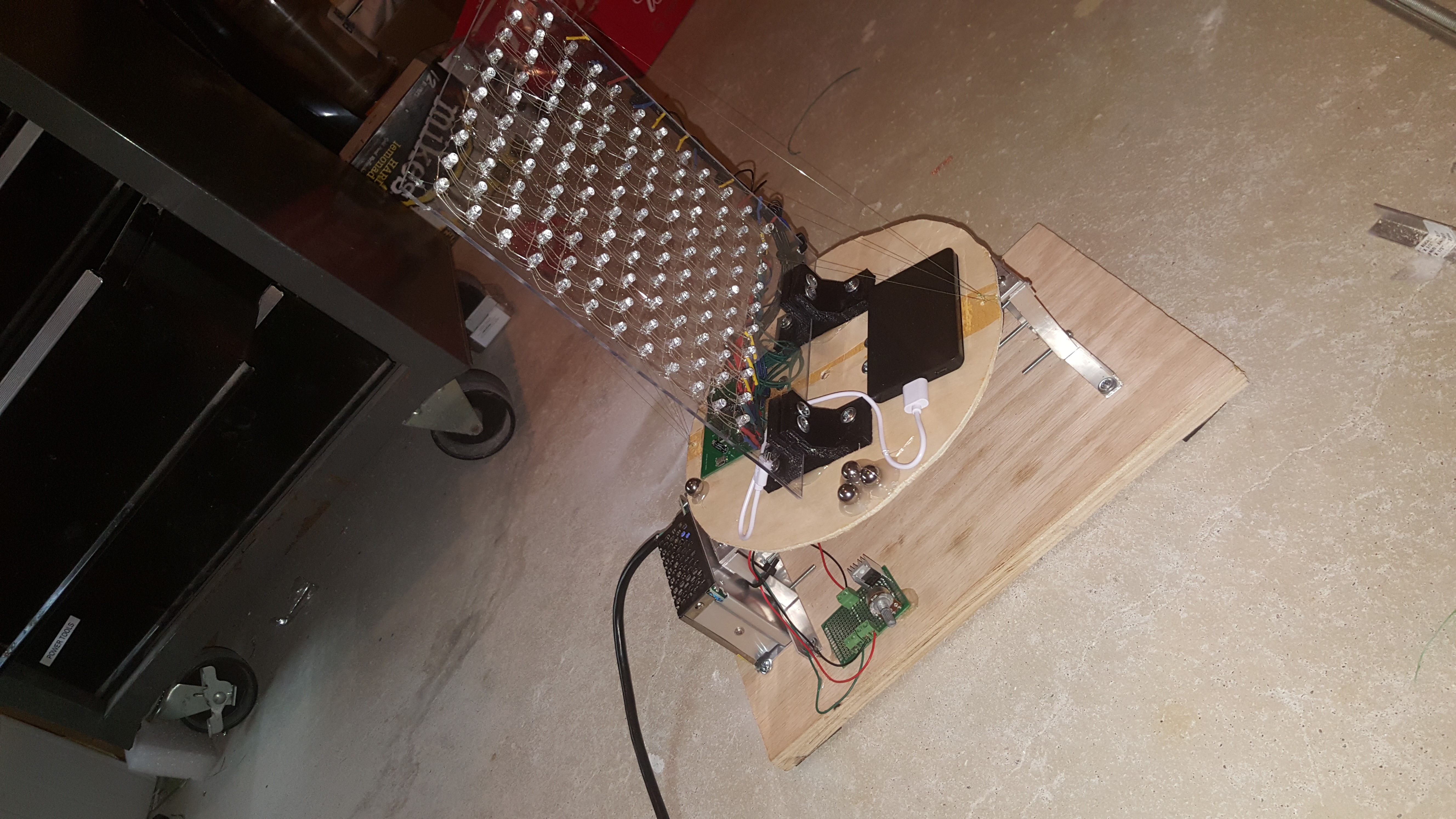
10/09/2018 at 02:40 • 0 comments![]()
Spent some more time on this over the weekend. The matrix was attached to some cheap board I had lying around cut into a half decent circle. the board doesn't really have any issue with vertical wobble which was my biggest concern, however it does still vibrate a decent bit at a high speed. after constructing the entire thing, I decided the top of the matrix needed some more support, so naturally fishing line was the perfect solution; it's strong and clear making it impossible to see when spinning. as for the balancing of the thing I knew this would be difficult, for the most part the foam stops on the bottom stop it from sliding around too much and it stays put at the speed I’m usually running it at, but it could be better. There are also ball bearings hot glued to the board to balance it.... it works... what more do you want?
I sped up the code some more on the control board, it had to be slowed down during development due to some strange power issues I was having which is a hilarious story in hindsight. Either way I’ll need to commit a few more hours at some point soon to code optimization to get this thing working ideally. Also need to program in some extra patterns for this thing so it's not only displaying 2 images all the time.
Additionally, I had to adjust a few of the 3d printed gears, specifically the smallest one attached directly to the motor. The gear was way too tall, and not giving enough thread to the nut for it to hold properly. quick rework and a 20-minute print and we were back up and running. also changed the large gear to give it more clearance on the aluminum stand.
Here's where the project stands:
- the base is fully assembled
- the matrix is attached and balanced (as well as I could manage)
- the entire system works consistently
what needs to be done:
- more patterns
- some recognition of the rotation so that patterns can be more diverse
- more balancing
- speed up shift register speed to reduce 3d "pixelation" as much as possible (see attached video)
- make it less loud? it kind of sounds like it's just plotting its opportunity to tear itself apart.
- work on the micro controller circuit that controls the ESC so that it automatically spins up to the desired speed. (which may make list item 2 irrelevant depending on how finely the motor can be controlled)
I strongly recommend turning your volume down before playing this video also, lots of flashing lights -
The Spinning Base
09/30/2018 at 18:14 • 0 comments![]()
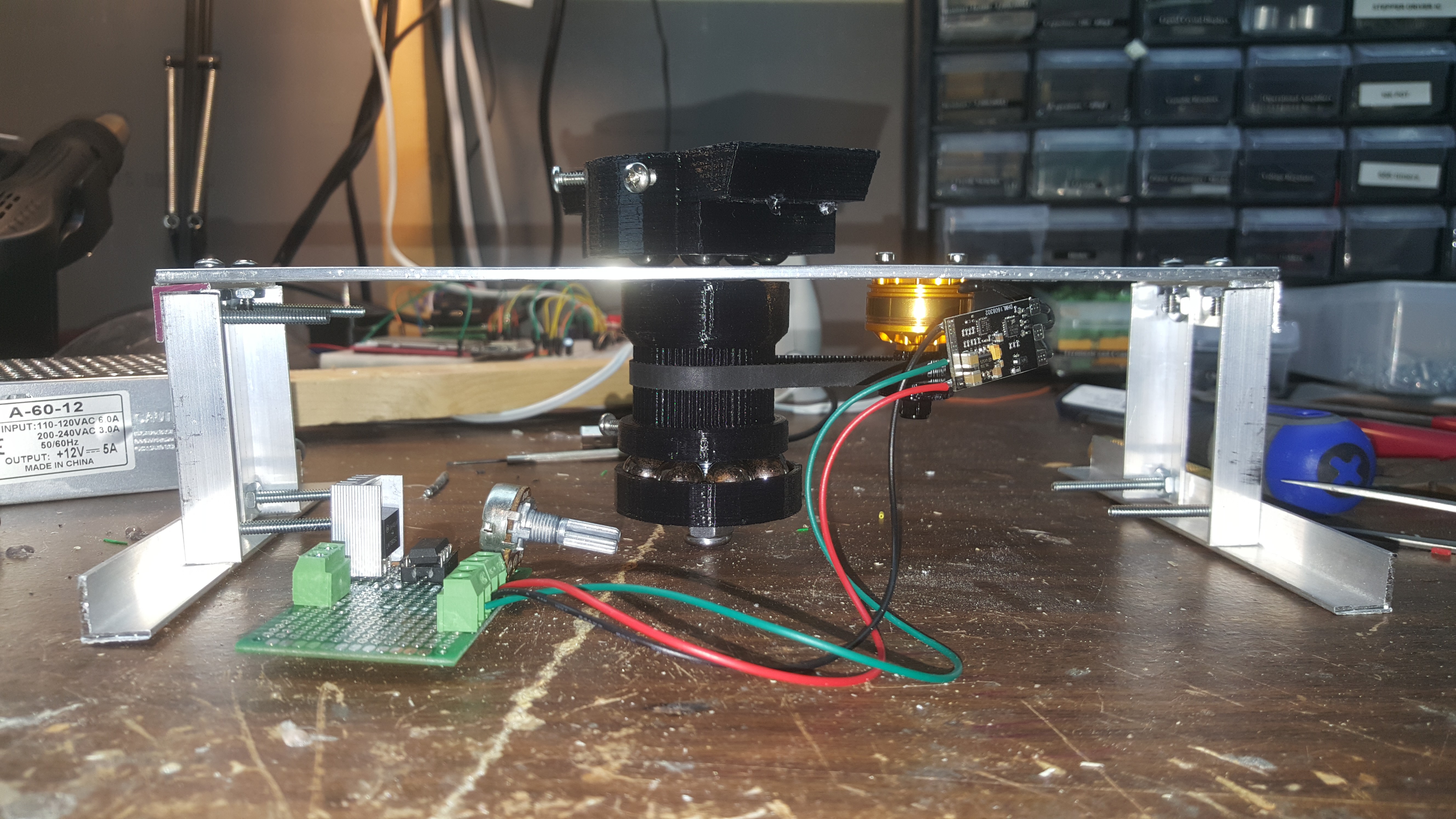
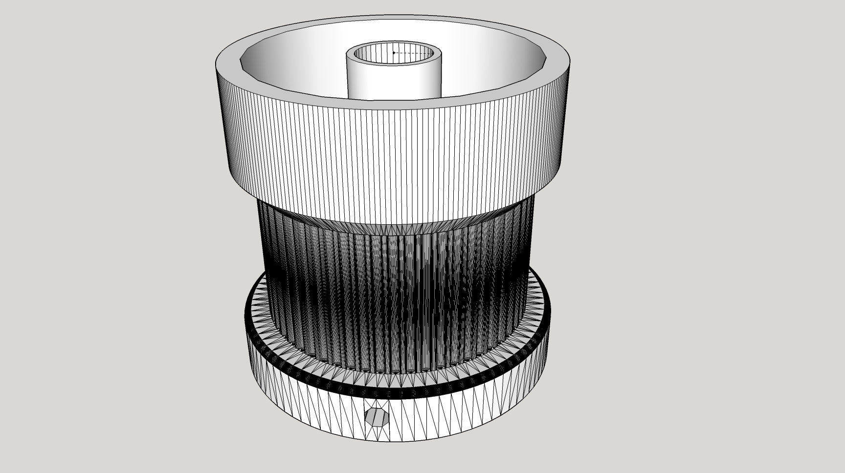
it's been a while since the last update, mostly due to school. the base for this project has been completed and is much different from what i had originally planned when i envisioned this project. for this part i decided to utilize a brushless FPV motor on a belt system to drive this project (only decently fast motor i had on hand, also i have a ton of ESCs sitting around). every part pictured was printed with 40% infill at 35mm/s and 15mm/s on the outside layer... which took a whole day after two prints failed. to drive the motor i whipped up an attiny circuit that's controlled by a potentiometer, and powered by 12 volts. I'm not really a mechanically inclined person so this part of the project was significantly more difficult for me than laying out the board or planning the circuity. The mechanical part of this was difficult and took quite a bit of time to complete:
![]()
I created the main gear using the customizer on thingiverse then customized it in google sketchup. You can find the parametric design i used here (https://www.thingiverse.com/thing:16627), credit really goes to droftarts here. The only real modification i made here was to add the space in the top to accept 1/4" ball bearings. This design utilizes a 5/16-18x3.5 bolt as the main shaft, while the bolt and nut hold the parts together vertically the ball bearings allow a low friction surface while keeping the gear and top mount from moving left or right. this design works pretty well actually, the only issue is that the combination of some ball bearings, an aluminum plate, and some rough 3d printed surfaces results in a lot of noise. however vibration is at an acceptable level and the noise isn't too loud. Might switch to proper thrust bearings if i get sick of hearing it.
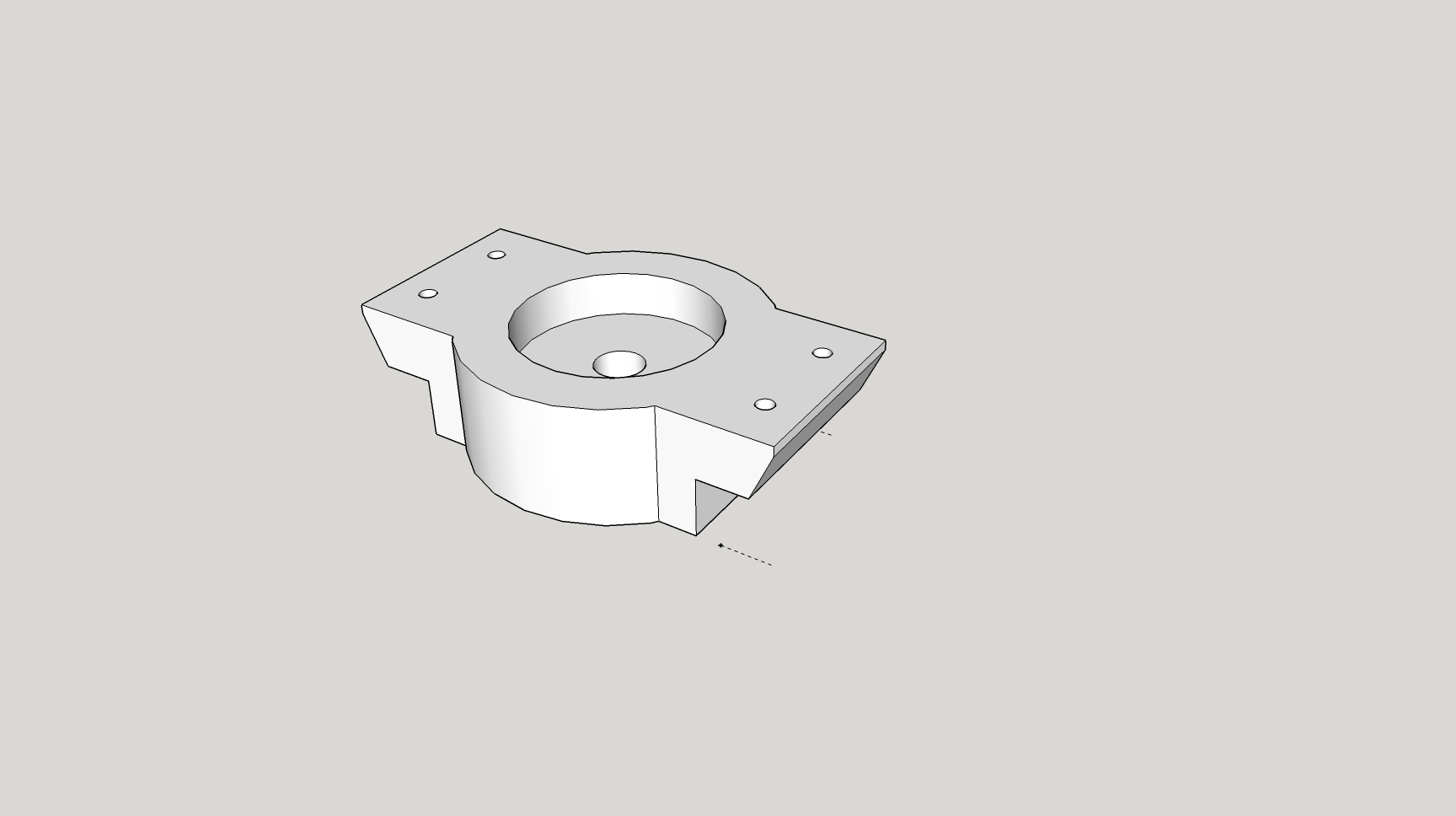
![]()
the top mount is simple, just some screw mounts and a hole for the bolt to go through. Additionally this one shares the same ball bearing design as the main gear.
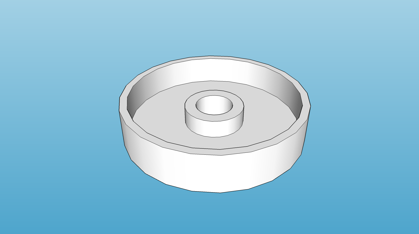
![]()
the only purpose this bearing serves is to prevent the main gear from having direct contact with the nut on the end of the bolt, this way the entire system can be locked down fairly tightly without resulting in too much friction on the motor.
the whole thing came together fairly well on the aluminum stand i made for this project in the early days while waiting for the circuit board to arrive. It's also almost scary how fast this system can spin, i don't intend to ever take it near it's top speed but it's cool nonetheless.
look forward to the next update when this project really comes together!
-
Big Update
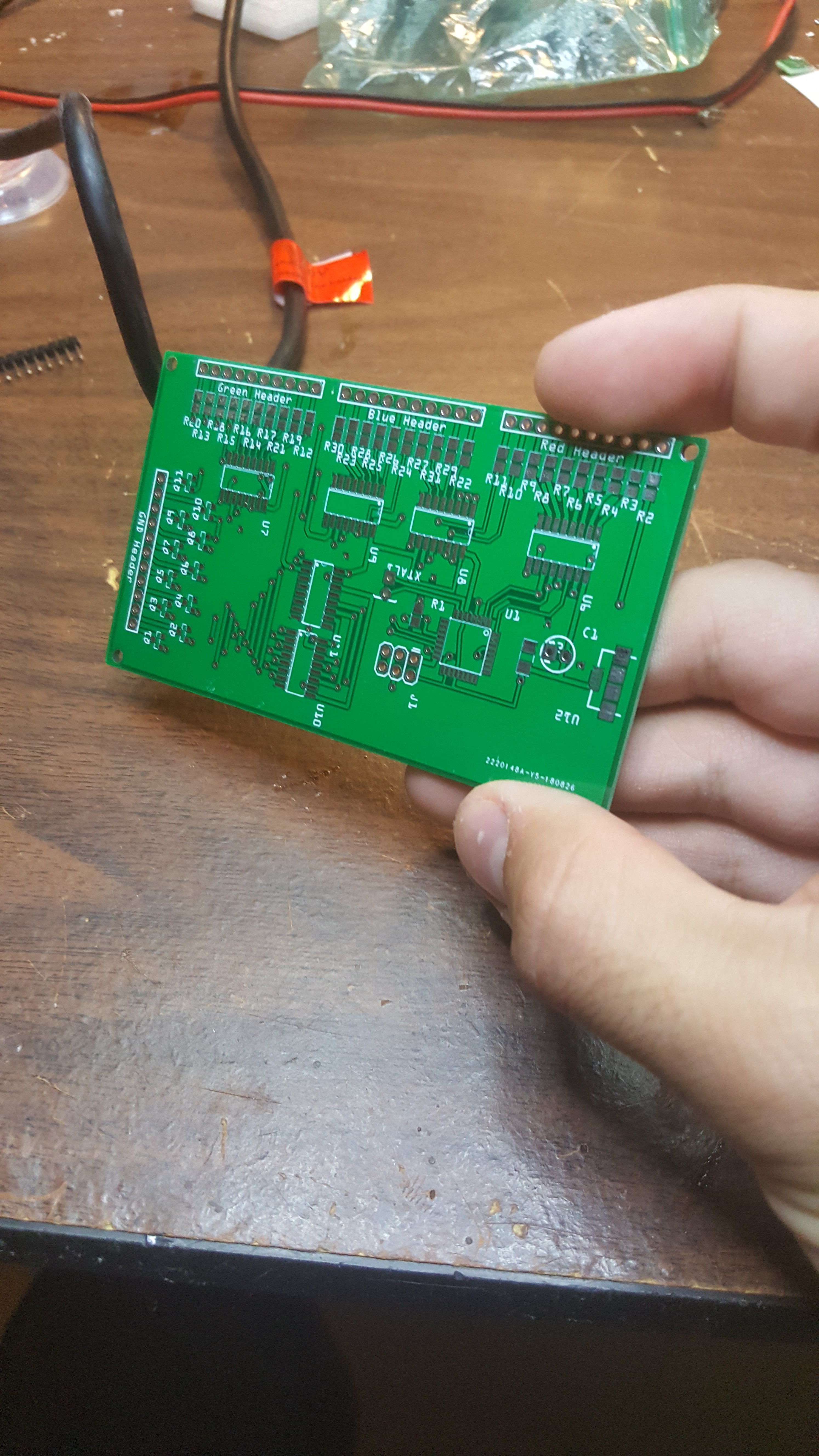
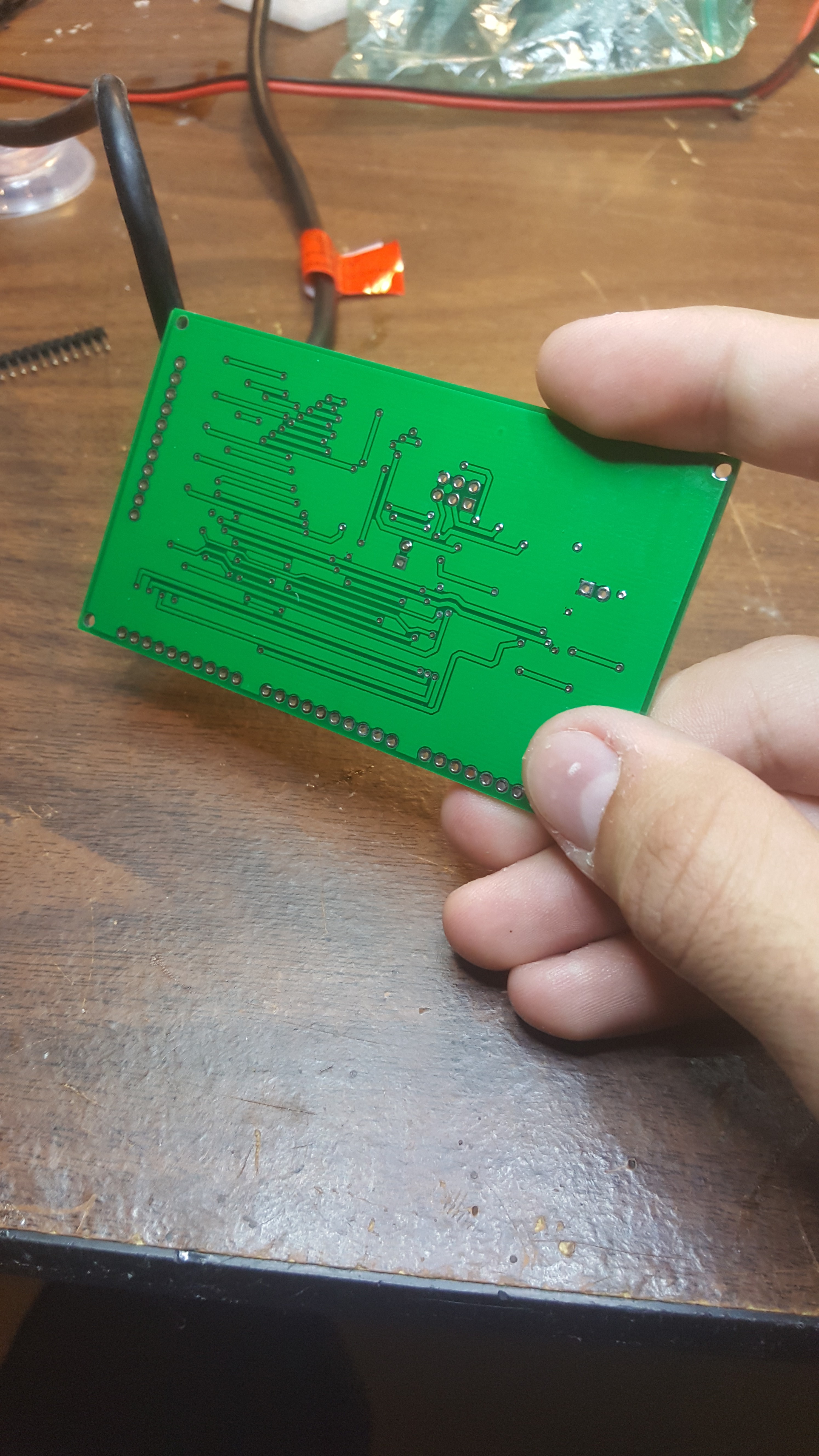
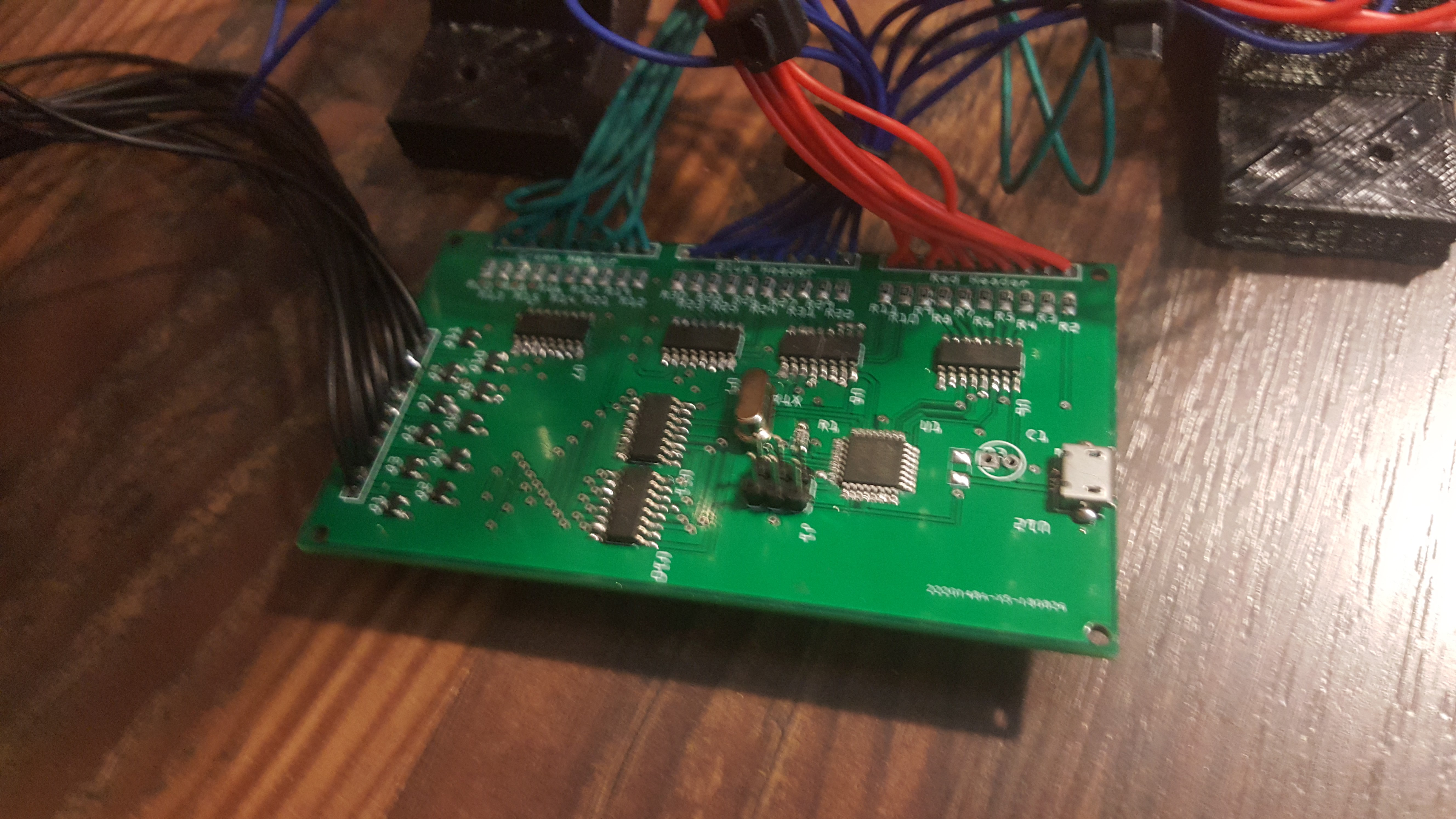
09/11/2018 at 15:17 • 0 commentsFirst off, i got the boards in hand and all the parts which was assembled last week. Everything looks great on them:
![]()
![]()
![]()
but when in originally went to go try to use the board well (as i would expect when things are going well) they didn't work. after a few hours of troubleshooting i discovered the issue. for whatever reason the atmega328 in a TQFP-32 package has a different device signature than the atmega328 in a DIP-28 Package. Which in all honesty makes sense, the TQFP has 2 extra IO pins, which could cause issues if someone were to upload a sketch that was originally for a different Atmega.
of course though, knowing what the issue is and how to fix the issue are two different things, spending some time browsing similar issues on various forums told me roughly what i had to do but nobody had encountered the exact same issue as me, the solution to getting a non-zero device signature in the arduinio IDE is more or less to modify the avrdude configuration file and just change the signature to whatever the chip you're using is. Fantastic, put that in and got a sketch to upload, the rest should be easy sailing right? i wish.
now the program could be uploaded through the ICSP header with a few little quirks. but the programming began. at first it was a straight forward attack strategy: start by using the digitalWrite to manually control the shift registers to get the desired pattern, after figuring out how it all works go with and try to make more complex patterns, then finally create some generalized functions that are easy to utilize to do whatever.
I ran into issues on the second part of that attack plan, i could get a pattern but not reliably. Regardless i stuck with it trying to work my way down to make more and more stable functions to handle different levels of the program. one of the major issues here was that the digitalWrite function wasn't nearly fast enough to deal with the shift registers, compounding issues further modifying registers directly in one go (PORTB = B10000010) seemed to cause the registers to do some weird things before finally putting power on the pins which messed with the shift registers. Finally changing the values directly utilizing the PORTB |= _BV(PD0); command solved almost all my issues and made the circuit function properly and allowed me to get the data out to the shift register correctly with very few issues.
aside from that the method that was used to display images in this project goes something like this:
- take 110 item byte array (0, 1, 2,3 represent color)
- taking the row count variable cut out the row we are working with and split into three color byte arrays
- feed those arrays into the shift registers to be displayed
- shift the high signal in the low-side shift register by one
- repeat.
the advantage to using the array to "draw" my images is that it's fairly easy now to add more images, just define them as a const byte to save on dynamic memory and set the array being displayed equal to it at will.
all and all, getting this thing working took me most of my weekend on-and-off and again. But if there wasn't going to be a challenge then this project wouldn't have been worth attempting.
unfortunately i don't have any images of this project working as i'm writing this so they'll be in the next project log.
Persistence of Vision LED Matrix
Because every project needs a twist.