Close
0%
0%

cyclabile

A moving, labile, bike lane projected on the road

Similar projects worth following
Cyclabile is an experiment about showing a moving bike lane on the road: the image moves according to the bike movement, producing the effect of riding on an actual bike lane, even when there isn't one.

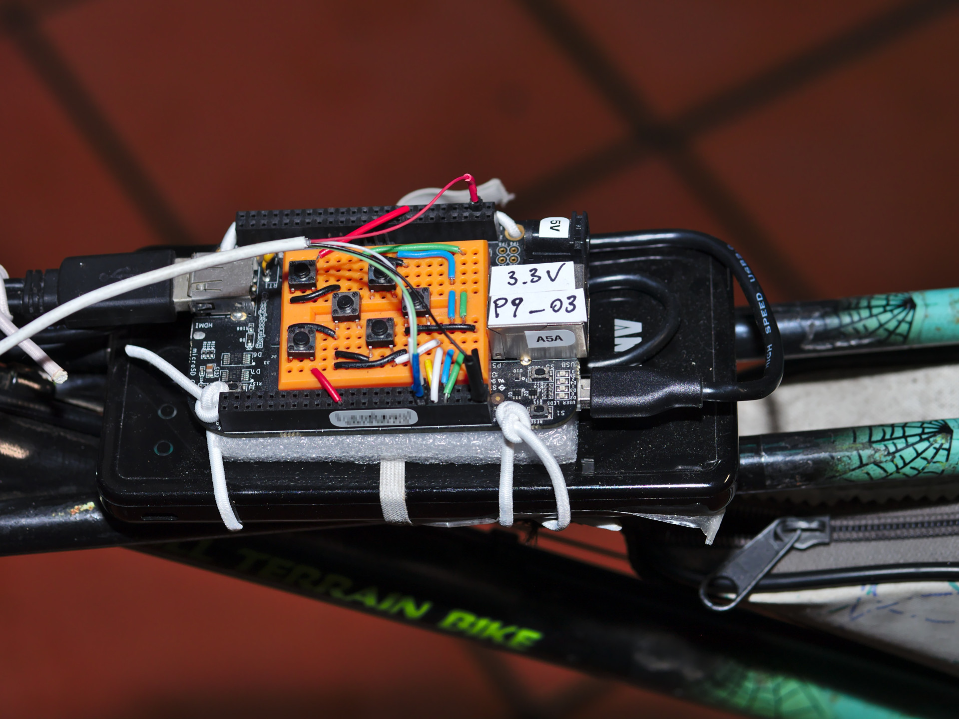
The idea for a projected bike lane came to me when I was working on the libam7xxx driver for USB pico-projectors and was also looking into keystone correction (in a way it started as a solution looking for a problem).

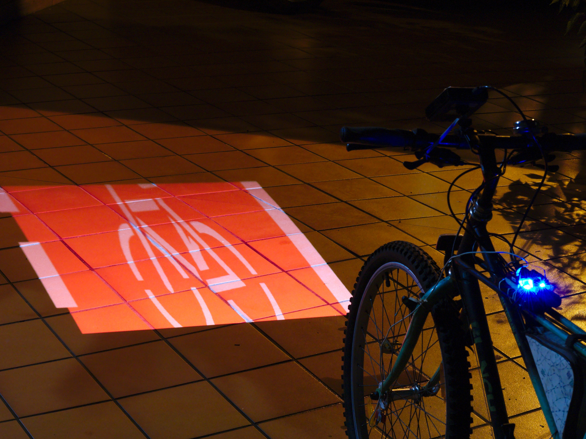
The effectiveness of projecting on the paving instead of signaling the presence with a traditional light can be argued, of course.

Even though there is a working prototype, for now the project purpose is more about having some fun and making a statement (there should be more bike lanes) rather than building an actual usable product.

The aim of a bike lane projected on the road is also to communicate to the general public that a bike can be used also at night, with the right urban environment and safety measures.

This made me think that it could qualify for the "Human Computer Interface Challenge", it's technology used to communicate something.

Admittedly, other projects accomplished something similar:

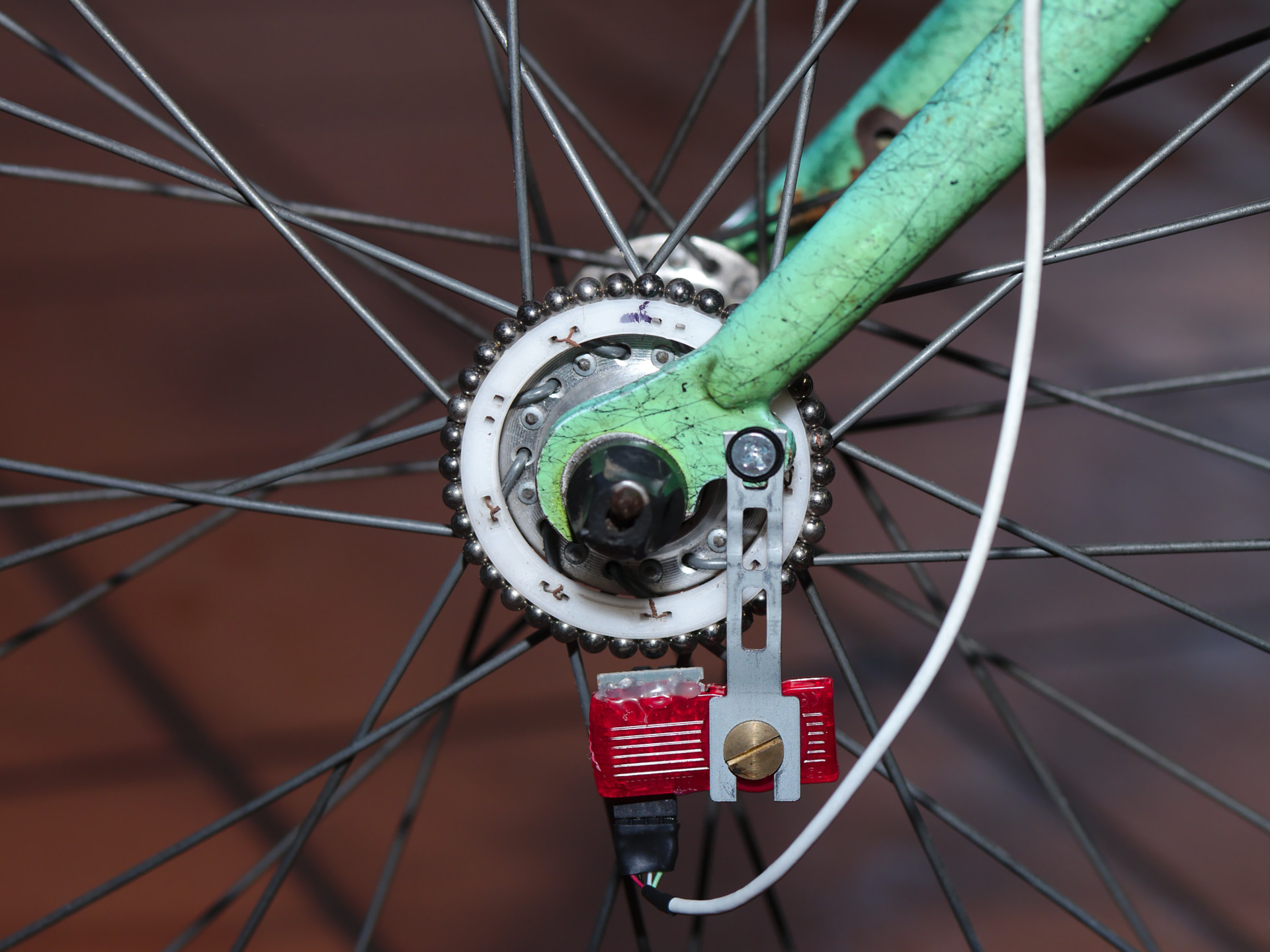
However cyclabile improves the effect of how the bike lane moves underneath the bike in a realistic way in order to simulate the feeling of being on an actual bike lane.

  • 1 × BeagleBone Black
  • 1 × USB projector supported by libam7xxx I already had one, for a new build a HDMI projector may be used too.
  • 1 × USB Y-cable needed for the USB projector to suppy some more current to it
  • 1 × USB power bank
  • 2 × latching Hall effect sensor

View all 7 components

  • Cyclabile, first working prototype

    Antonio08/26/2018 at 22:01 0 comments

    From https://ao2.it/139

    Cyclabile is an experiment about showing a moving bike lane on the road: the image moves according to the bike movement, producing the effect of riding on an actual bike lane, even when there isn't one.

    The effectiveness of projecting an image on the paving instead of using a traditional light can be argued, of course.

    For now the project purpose is more about having some fun and making a statement (there should be more bike lanes) rather than building an actual usable product.

    The prototype has been developed with a BeagleBone Black and a USB projector supported by libam7xxx because I already had those around, however if I were to start from scratch I would use a Raspberry Pi and a HDMI pico-projector, which would make the software side more flexible (graphics acceleration, no need for display-dependent code), or even a wireless projector and a BLE sensor connected to a smartphone.

    The source code of the prototype is at https://git.ao2.it/experiments/cyclabile.git/.

    A keypad makes it possible to adjust some parameters to correct the keystone effect caused by the projection not being perpendicular to the ground:

    Cyclabile - Keypad

    A reasonably precise rotary encoder, with a support to mount the magnets on the front wheel of the bike, detects movement at very low speeds.

    Cyclabile - Rotary EncoderHere are some more pictures of the build:

    Cyclabile - Overview

    Cyclabile - Demo

    Similar projects

    I am aware that there are similar projects around, but I guess what Cyclabile tries to accomplish is to make the scrolling of the projected image more realistic, to recreate the effect of a real bike lane.

    Safety First

    "Safety First" is an art installation by Vladimír Turner and Ondřej Mladý very much in the spirit of Cyclabile.

    The difference is that Cyclabile is more portable and more interactive, the bike lane moves depending on the bike movement while "Safety First" used a video recording in a fixed loop.

    Bike Projector Headlight

    This is more generic, it's used to display info on the road, not specifically a bike lane.

    Lightlane

    A laser bike lane, it projects a static image.

  • 3D-printed holder for magnetic spheres built with OpenSCAD

    Antonio08/26/2018 at 10:54 0 comments

    From https://ao2.it/138

    When I built the low-cost and precise rotary encoder with magnetic spheres I used 21 spheres because they fitted nicely in the other parts of the build I had around.

    However, if an arbitrary number of spheres is to be used then an appropriate holder must be built.

    The magnetic spheres are 5mm in diameter. Knowing the number and the radius of the external spheres it is possible to calculate the radius of a circle surrounded by adjacent circles by using the inverse formula for the Numbers of circles around a circle.

    I firstly wrote a test program (draw_circle_surrounded_by_circles.py) as a proof of concept, and then used the same math to build a 3D model with OpenSCAD.

    OpenSCAD makes it easy to build parametric objects:

    OpenSCAD - Tetramag spheres holder animation

    I chose a number of spheres to match a minimum internal radius that was needed to fit the holder on a bike wheel, the nine couples of square holes are for tying the holder to the spokes.

    The source code is in the OpenSCAD-Tetramag_spheres_holder git repository.

    The end result is not bad and fits the wheel quite nicely:

    Tetramag spheres holder mounted on a bike wheel

    Tetramag spheres holder mounted on a bike wheel

  • Linux Device-Tree and gpio-keys driver on BeagleBone Black

    Antonio08/26/2018 at 10:47 0 comments

    From https://ao2.it/137

    I had to wire up a simple navigation keypad to a BeagleBone Black for a prototype, and I used the gpio-keys driver configured via a device tree overlay.

    I looked for some free GPIO pins so that the keypad could be hooked up with minimal changes to the BeagleBone Black default configuration.

    I am posting some details in case anyone (future-self included) needed to do the same.

    Here is a table of the pins and the related keys.

    Header PinFunction
    P8_07Up
    P8_08Left
    P8_09Right
    P8_10Down
    P8_26Enter
    P9_15Esc

    I did not use P8_11 and P8_12 because they can be configured in eQEP mode and I intended to use them for a rotary encoder.

    Here is a picture of how the keypad can be hooked up using a breadboard.

    Navigation keypad with BeagleBone Black

    And a quick video to show the functionality:

    The devicetree overlay can be found at git.ao2.it/experiments/bbb-gpio-keypad.git/ and can be built and installed by running make && sudo make install, after getting the needed include files as explained in the Makefile.

    Nowadays, devicetree overlays on the BeagleBone Black have to be set via the bootloader by changing the file /boot/uEnv.txt, in this case the following change was enough:

    --- /boot/uEnv.txt.orig 2018-07-13 13:28:12.837315343 +0000
    +++ /boot/uEnv.txt  2018-07-13 13:27:59.525770867 +0000
    @@ -11,7 +11,7 @@ uname_r=4.9.105-ti-r112
     enable_uboot_overlays=1
     ###
     ###Overide capes with eeprom
    -#uboot_overlay_addr0=/lib/firmware/<file0>.dtbo
    +uboot_overlay_addr0=/lib/firmware/bbb-gpio-keypad-00A0.dtbo
     #uboot_overlay_addr1=/lib/firmware/<file1>.dtbo
     #uboot_overlay_addr2=/lib/firmware/<file2>.dtbo
     #uboot_overlay_addr3=/lib/firmware/<file3>.dtbo

  • Low-cost and precise rotary encoder with magnetic spheres

    Antonio08/26/2018 at 10:44 0 comments

    From https://ao2.it/135

    You know what they say that constraints drive creativity, I think this post is just another little example of that.

    Usually I do not put time constraints to my hobby projects, but I make sure to have some other kind of constraints, like keeping the cost low and trying to reuse stuff that I already have.

    In this case I needed a way to measure the angle and speed of a rotating object for some of my projects, and I wanted a rotary encoder that was inexpensive, but precise enough to work at very low speeds.

    I ruled out optical encoders (I could have reused a mouse) because there could have been noise issues in the final project, so I decided to go magnetic.

    I purchased a couple of Hall effect sensors but I had no idea of how I was going to use them.

    Later I realized that the US1881 sensors I bought were bipolar latching sensors (check out the Hallbook for a nice reference of magnetic sensing), meaning that their state would persist when the magnet was out of reach.

    These kind of sensors are not designed to be used with the magnetic pole facing the sensor, in a reed-switch fashion, they require alternating magnetic poles to switch states; most of the time these Hall effect sensors are used with ring magnets.

    I didn't want to buy a different sensor (unipolar ones may work better with sparse magnets) or a dedicated ring magnet, so I started to think about how to build a ring magnet from what I had lying around.

    One way to build a ring magnet is to place small magnets with alternating poles in a circular arrangement, like proposed in Custom 3D Printed Magnetic Encoder Disks for Robotics Projects by Erich Styger.

    However I don't have a 3D printer, nor such small magnets, but I had around a Tetramag: a toy made of magnetic spheres.

    The Tetramag spheres have a diameter of 5mm, that means that a pole covers about 2.5mm (pole pitch) and that the "element pitch" (the distance between the two sensing elements) should be of about 1.25mm.

    Check out the section about quadrature in the Hall-Effect IC Applications Guide from Allegro Microsystems for more info.

    In practice, though, the two sensing elements do not necessarily need to be adjacent and cover the same magnet, it's enough that they are in a position which results in a quadrature signal: with the two channels being out of phase of about 90 degrees, like shown in the following picture:

    Tetramag ring magnet - element pitch

    And here is a photo of the sensors position in real-life:

    Hall effect sensors position

    In my demo setup, a piece of a pen was used as the spindle and pieces from a CD stack case are reused for the knob of the encoder:

    Rotary encoder demo setup

    The result is a low-cost rotary encoder, with a precision depending on the number of spheres used to build the ring.

    Look at the demo built with 21 spheres:


    In this case the encoder has 21 x 4 = 84 pulses per revolution (it's a 2 channels quadrature encoder) and can measure angles down to 360 ÷ 84 = 4.29 degrees.

    The code of the experiment can be found at git.ao2.it/experiments/Hall_effect_rotary_encoder.git

    And now that I know more about Hall effect sensing I can decide whether a better sensor can be used for my next project: it may actually make sense to use a single dual sensor instead of two discrete sensors.

    But you don't know until you know, right?

View all 4 project logs

  • 1
    Build and execute cyclabile

    Follow the build logs for all the details.

    To recap, the source code is here:

    All the source I wrote is GPL.

    Make sure the device-tree overlays are enabled in /boot/uEnv.txt on the BBB as explained in https://ao2.it/137,

    Other dependencies are available in Debian and can be installed with the following command:

    $ sudo apt-get install libam7xxx0.1 libturbojpeg0 liblept5
    

    To build the main project on the BeagleBone Black execute the following commands:

    $ git clone https://git.ao2.it/experiments/cyclabile.git/
    $ cd cyclabile
    $ make NEON=1 EQEP=1
    $ sudo make enable_service
    

    And then connect the USB projector to have cyclabile start automatically.

    The cyclabile software can also be tested on a normal desktop PC, emulating the encoder with the mouse wheel, and using the keyboard for the navigation keypad, try the following command:

    $ git clone https://git.ao2.it/experiments/cyclabile.git/
    $ cd cyclabile
    $ make && sudo make run
    

View all instructions

Enjoy this project?

Share

Discussions

Similar Projects

Does this project spark your interest?

Become a member to follow this project and never miss any updates