0%
0%
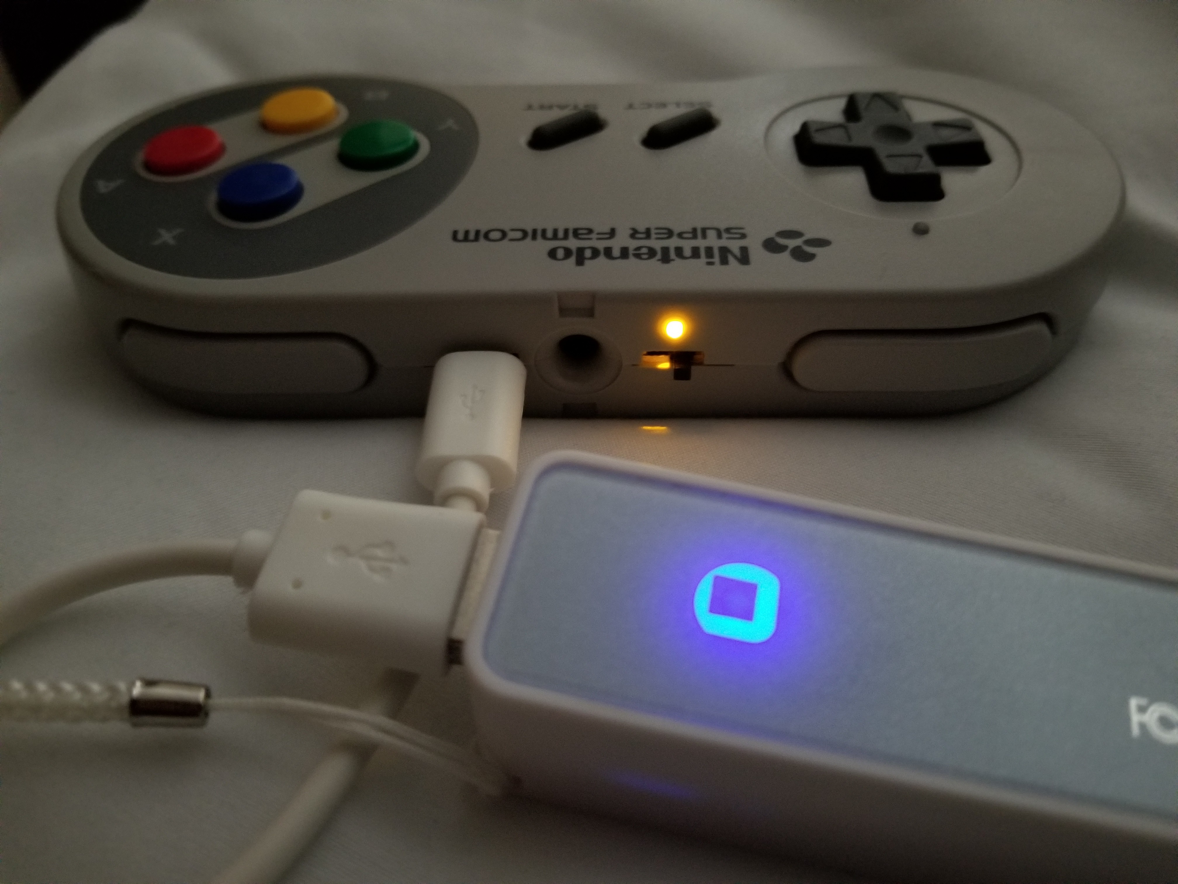
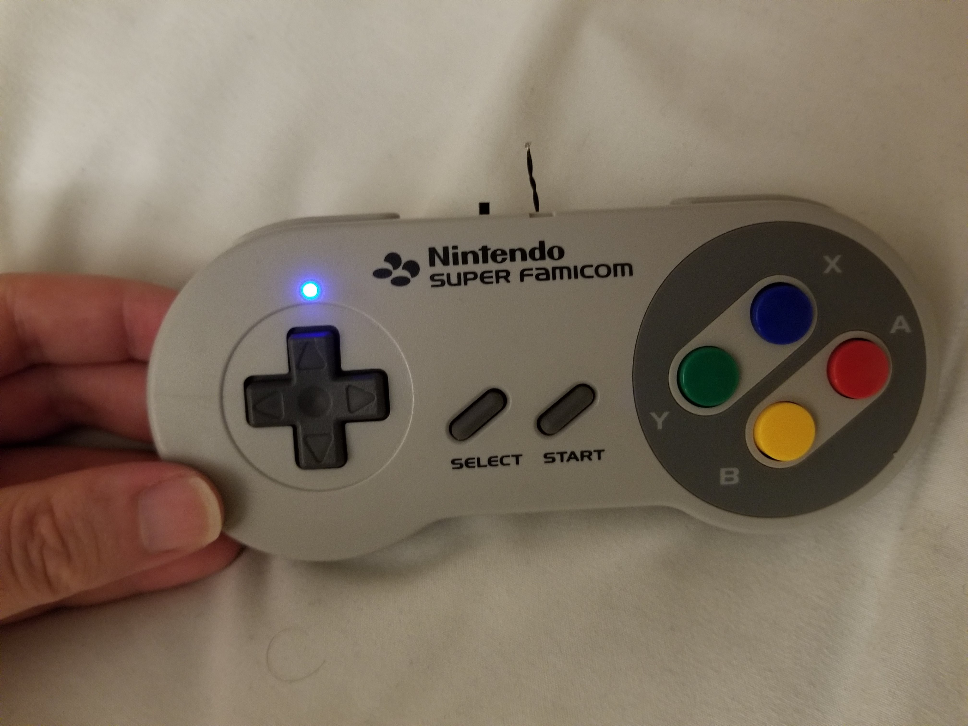
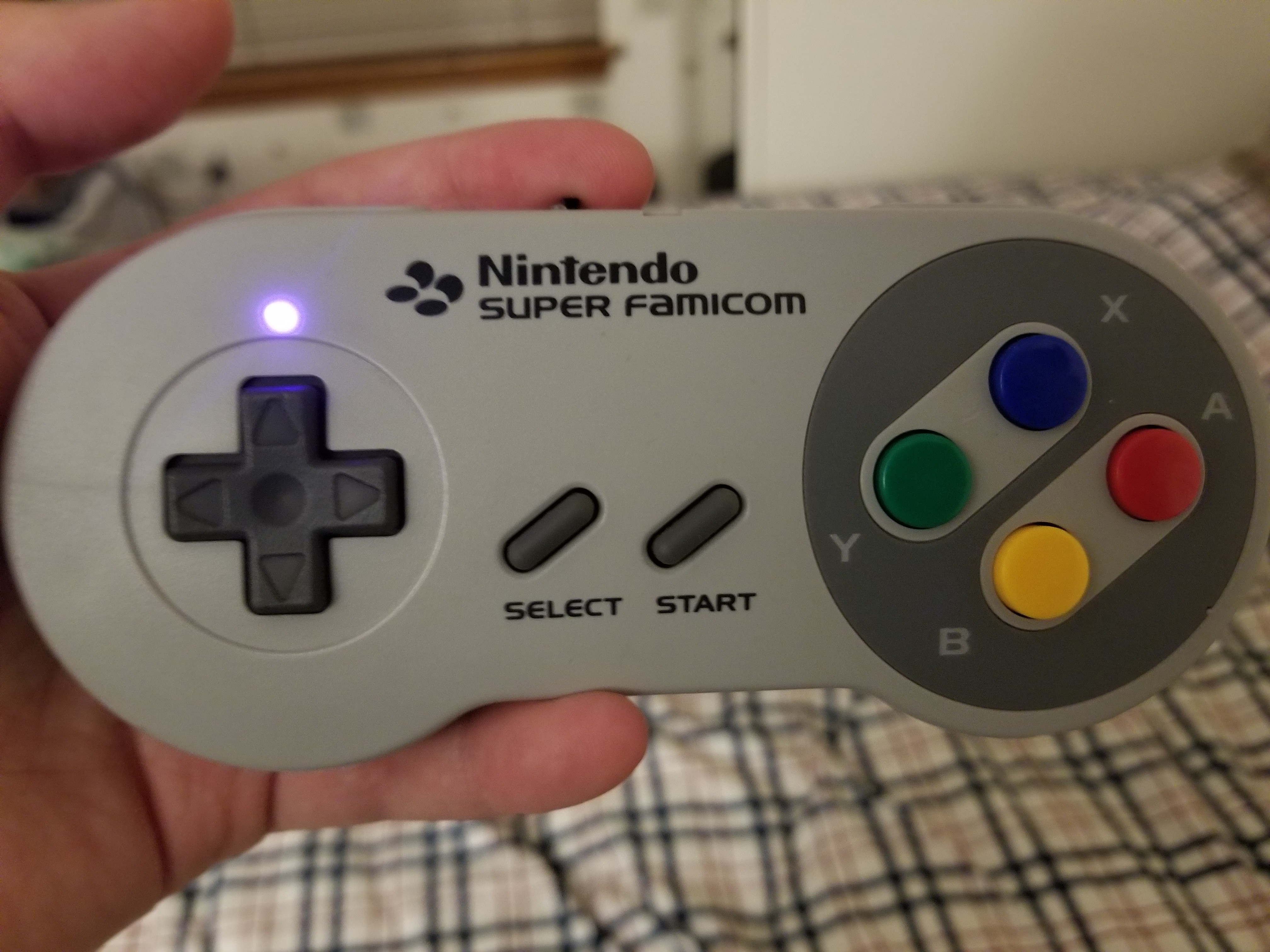
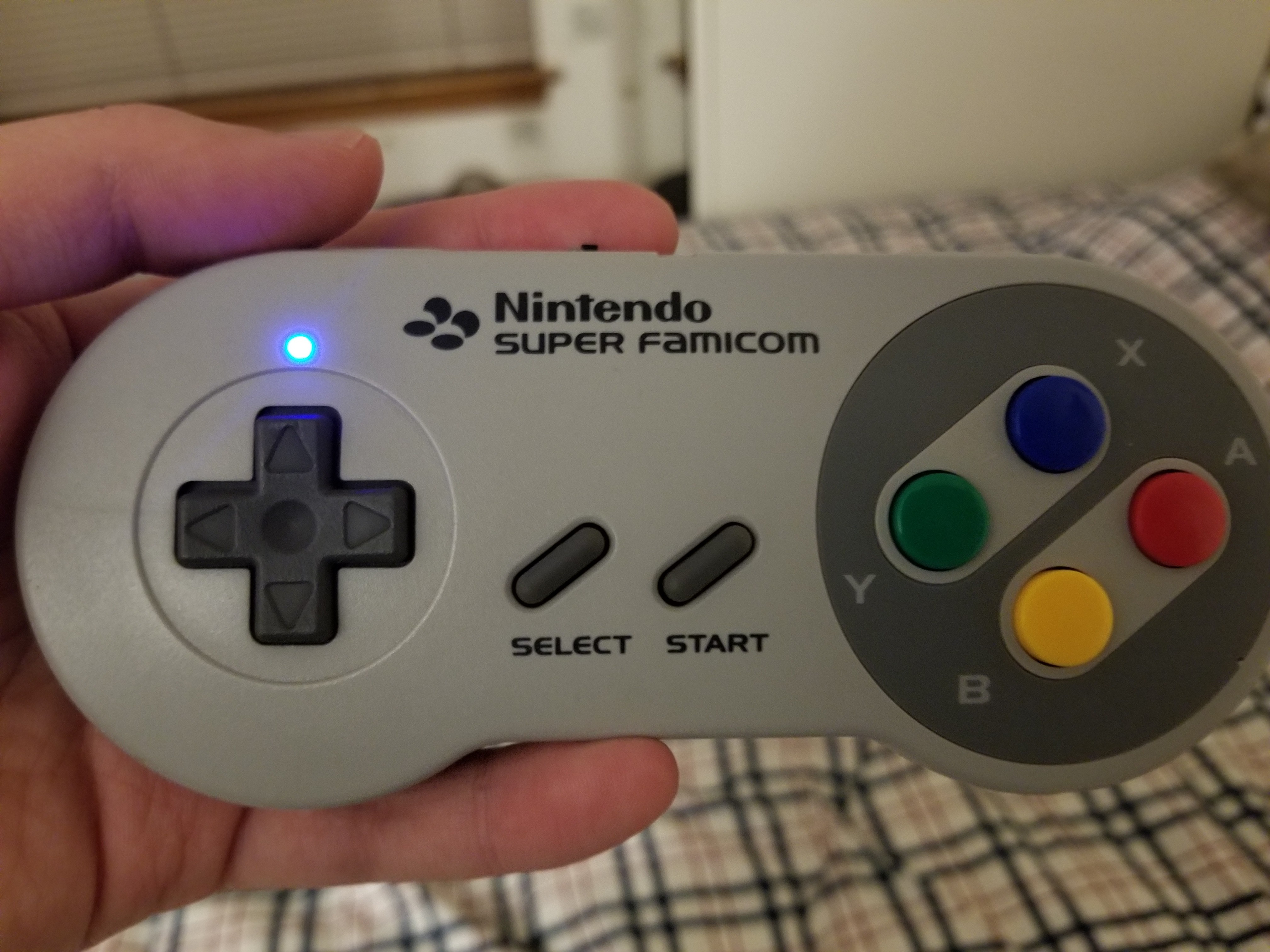
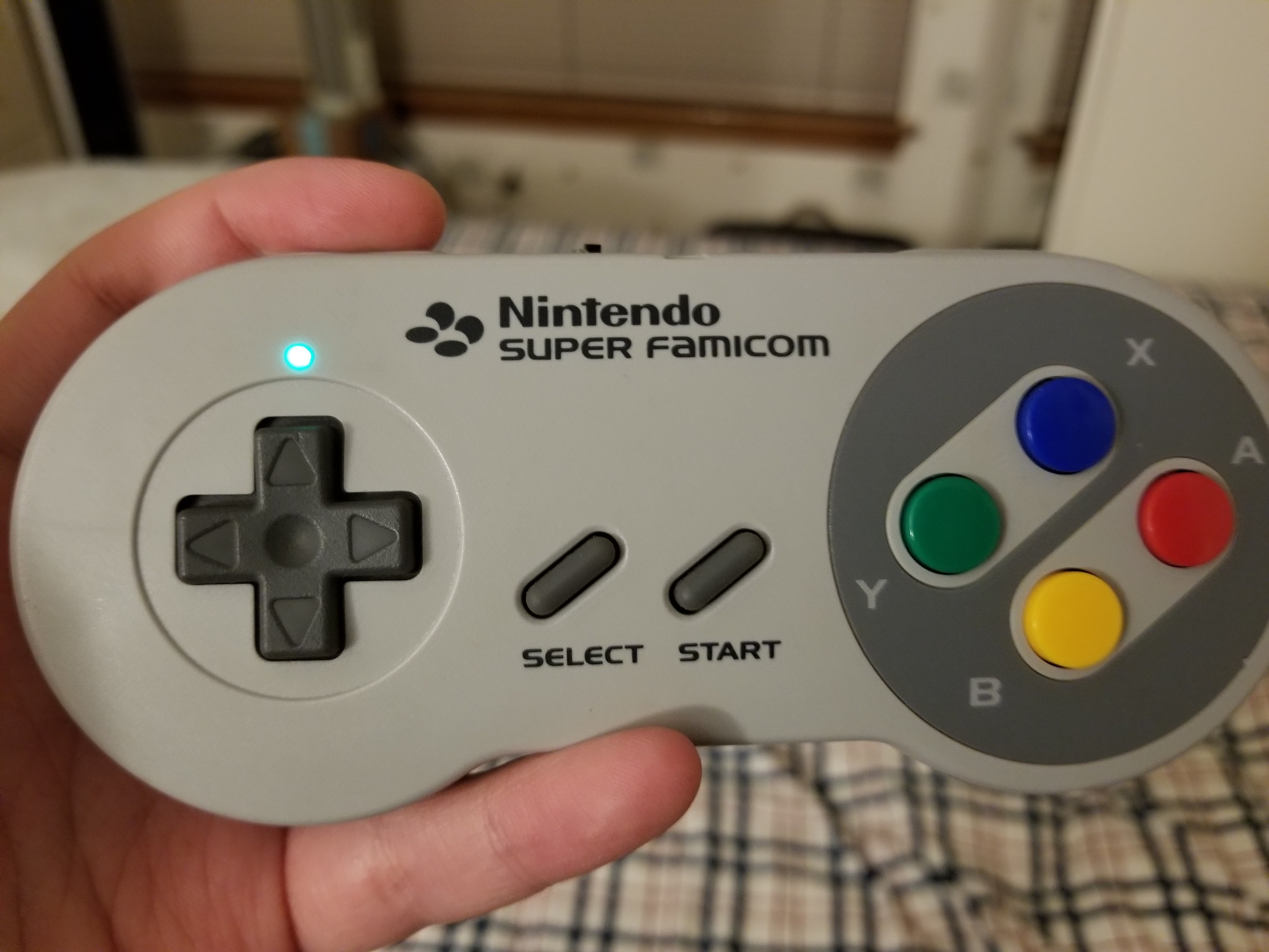
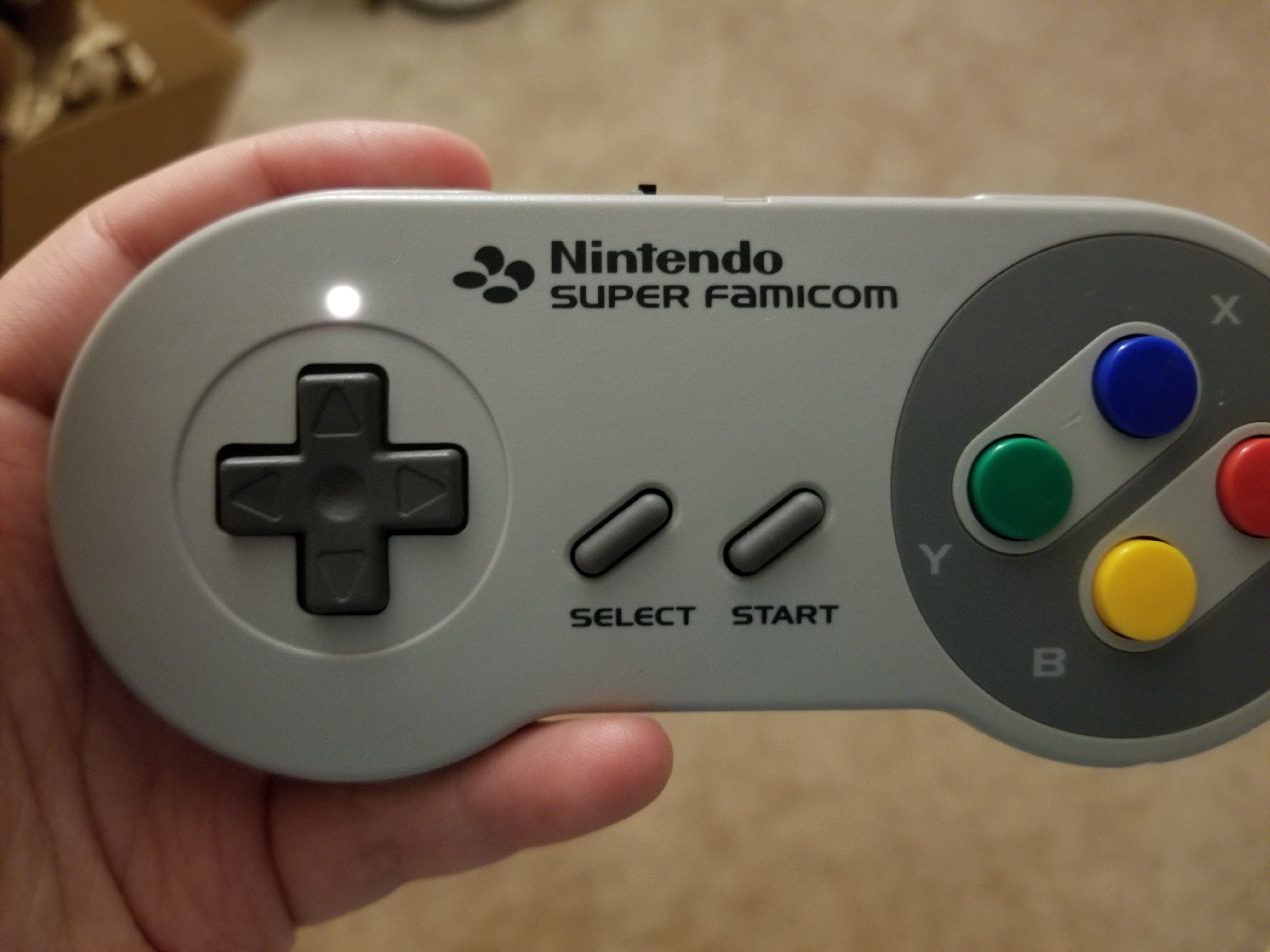
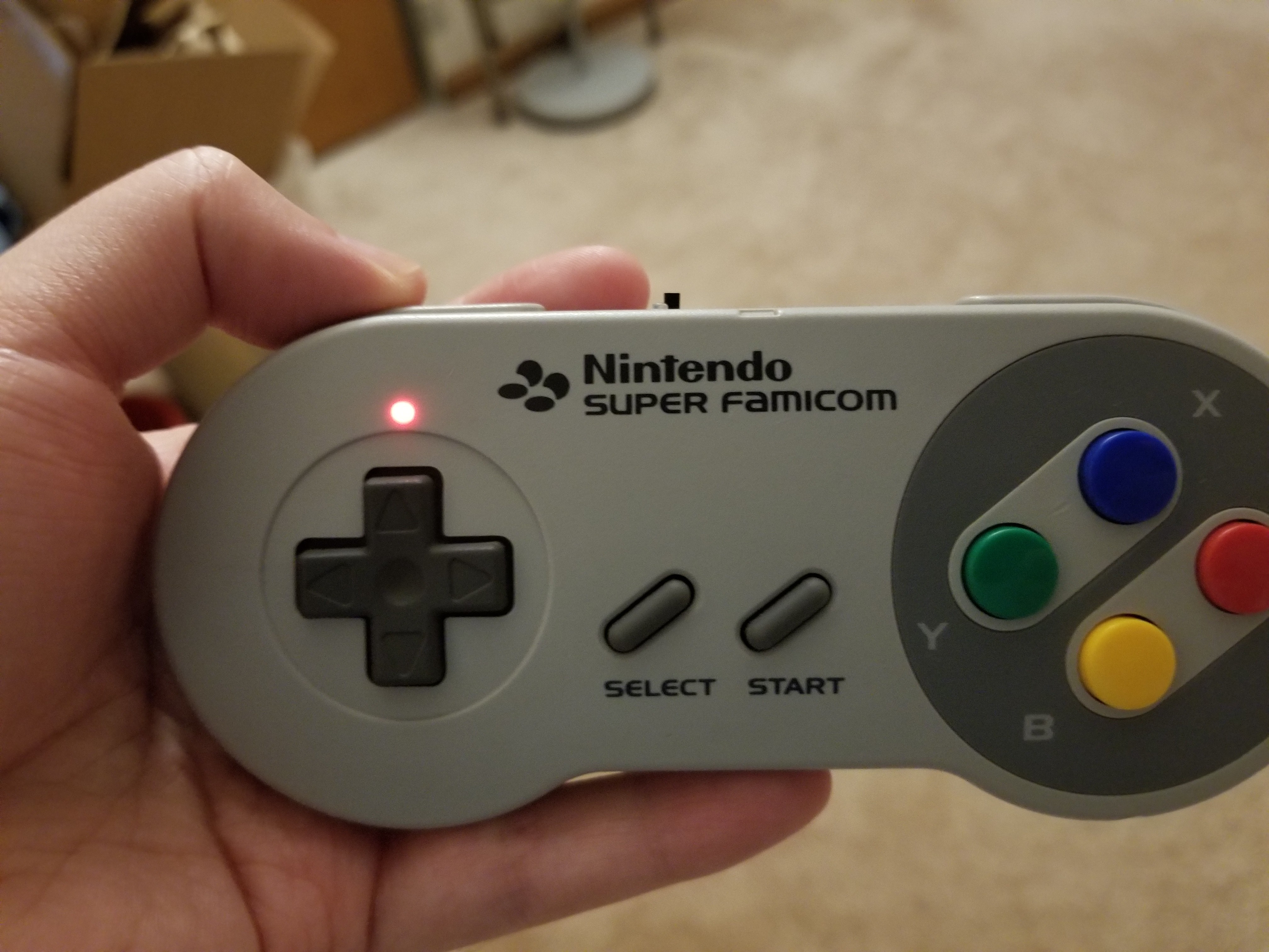
DIY Bluetooth SNES Classic Controller
Exactly as the title says, I built a bluetooth controller out of a SNES controller and dongle for use with Nintendo's mini classic consoles.
 sjm4306
Become a Hackaday.io member
Already have an account? Log in.
Just one more thing
To make the experience fit your profile, pick a username and tell us what interests you.
Pick an awesome username
hackaday.io/
Your profile's URL: hackaday.io/username. Max 25 alphanumeric characters.
Pick a few interests
Projects that share your interests
People that share your interests

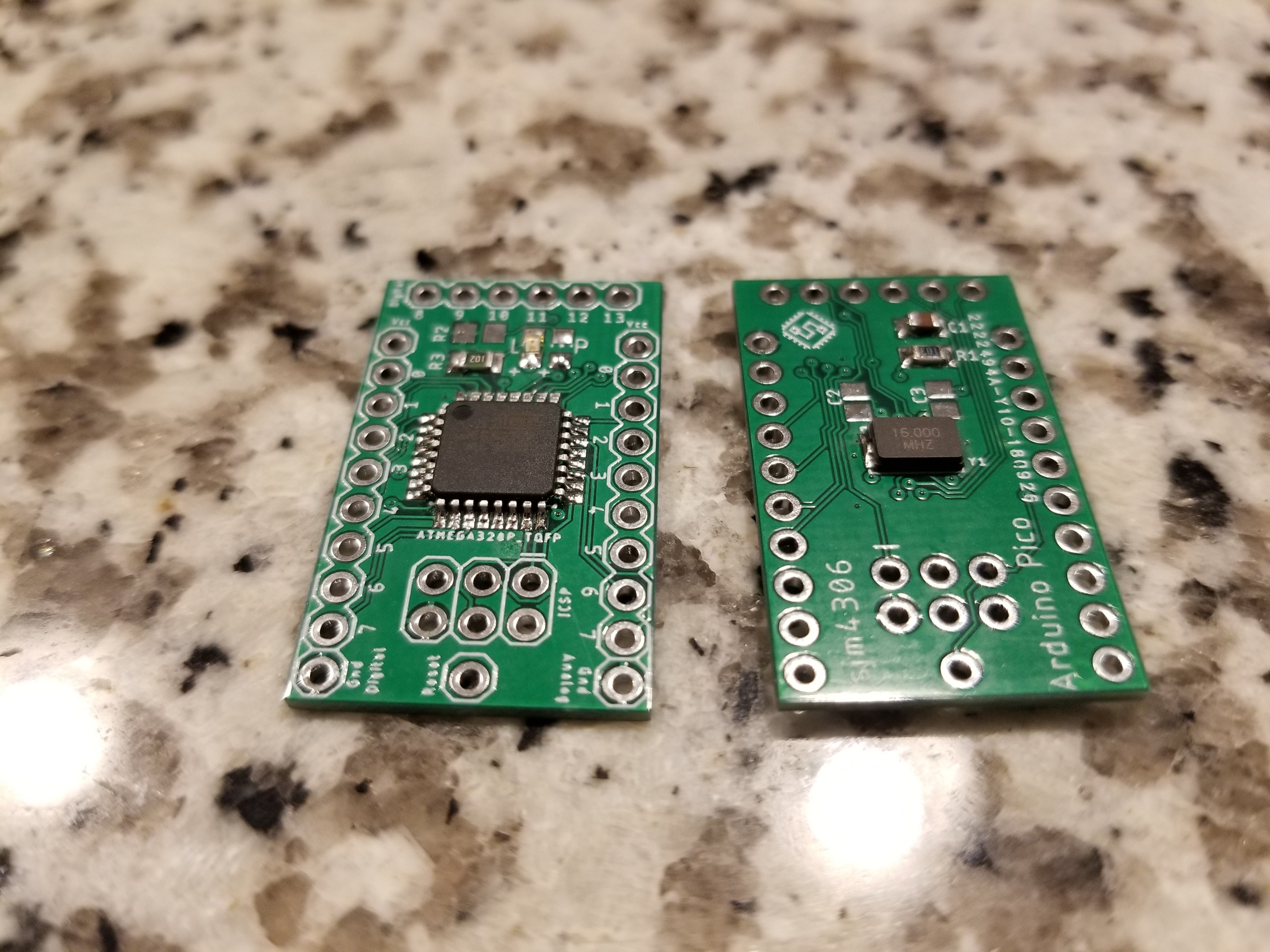
 Next up, the software runs on an ATMEGA328P with each the transmitter and receiver having their own controller on tiny little general purpose boards I designed and ordered through my sponsor JLCPCB (thanks a bunch!!!). Check them out here: $2 PCBs (in 48hours):
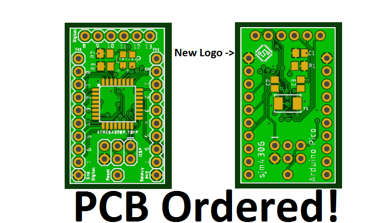
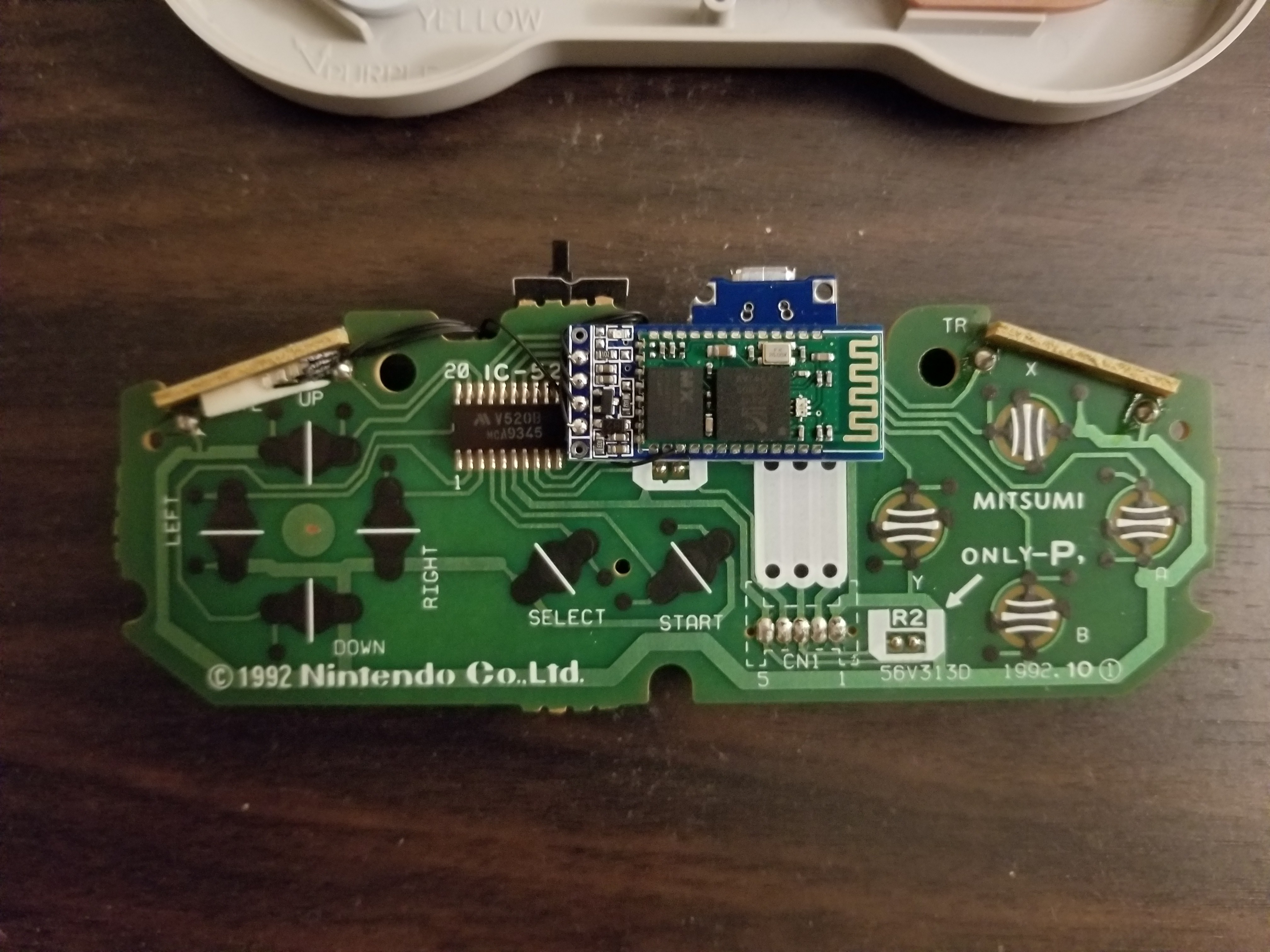 The battery (a 330mAh 3.7V cell) and charging circuit with micro usb are on the back left hand side. The atmega328p and 3.3V LDO regulator are on the right here.
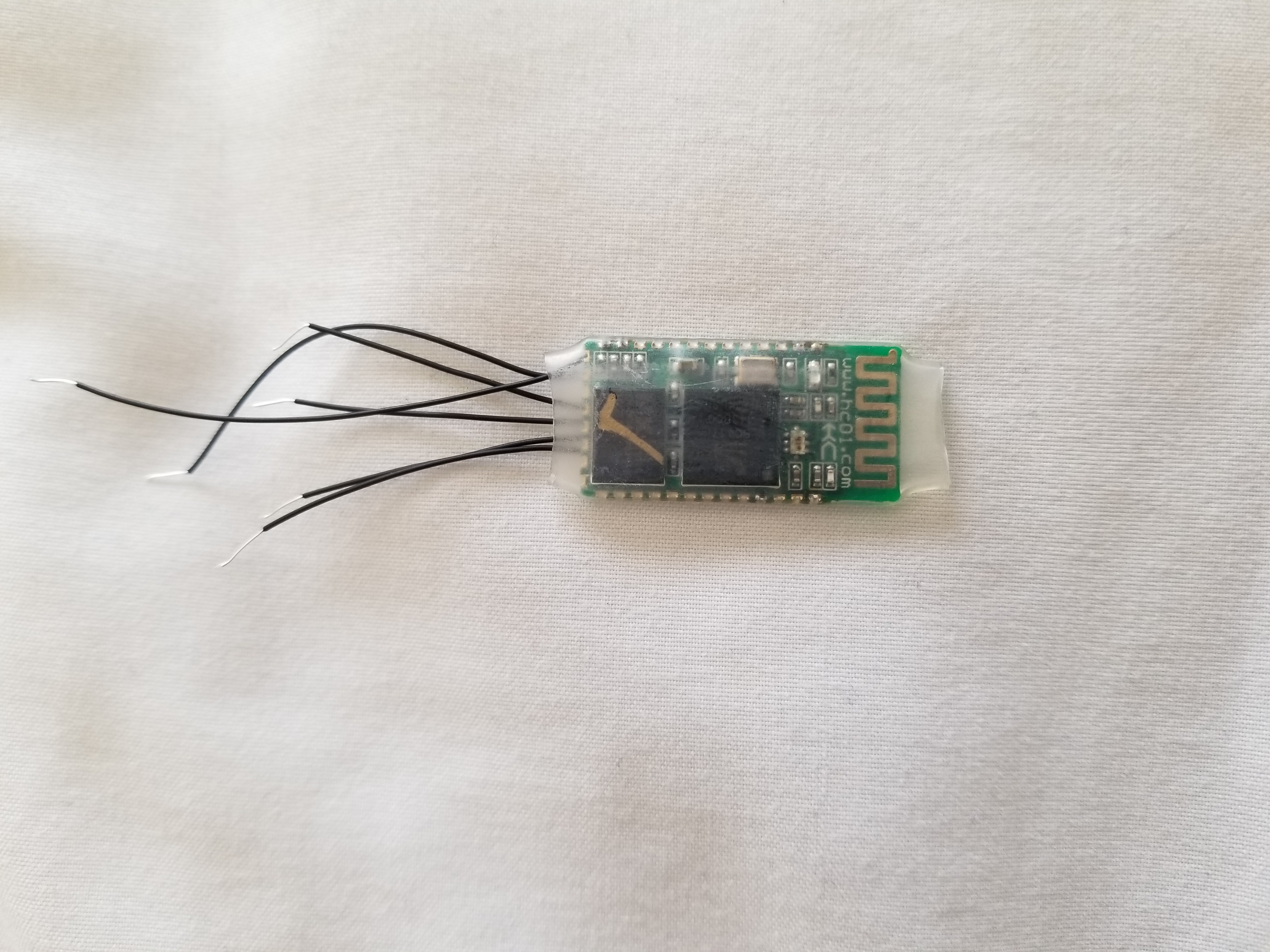
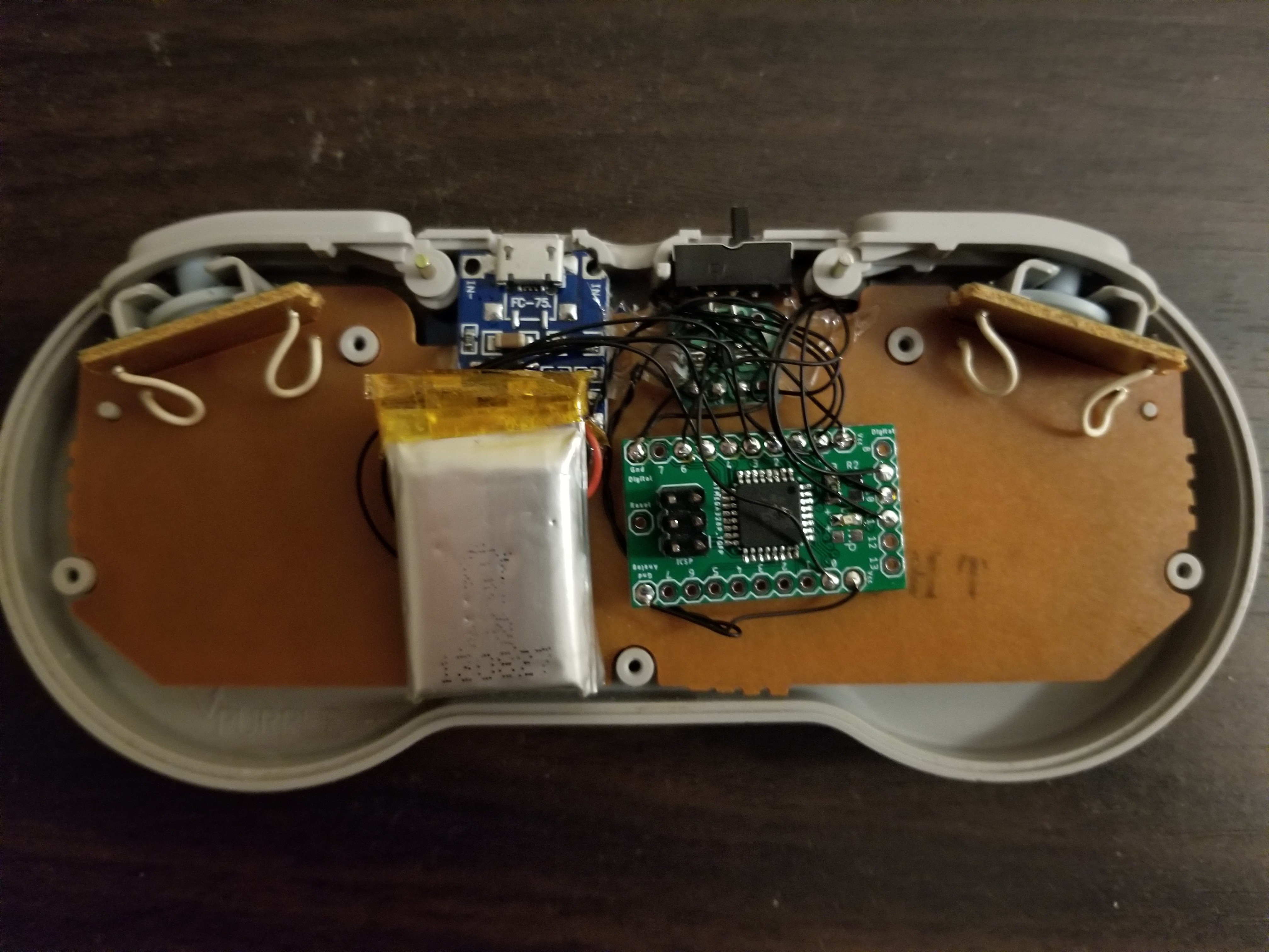 On the receiver side I use the same board I designed and attach it to the bluetooth module over serial and also to the classic console plug over i2c (see bbtinkerer's page for info about the protocol and connections for i2c). The software just receives packets, picks out the button states, and finally send it to bbtinkerer's function which assembles the i2c packet and sends it over i2c to the classic console.


 danjovic
 justin.richards
 Rob Smith
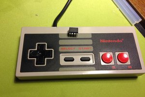
Ahh, doesn't this look fantastic!
I love that you finished up by adding remapp-pability of the keys. That's the part that often sucks with controllers (well, apart from the steam controller ;) )
I'm tempted to make one of these myself now! Though I might be tempted to switch to an ESP-Pico instead of an AVR...
I wonder how useful a small app to monitor the controller would be. It'd be easy whipping something up in Qt to check the battery voltage and set key remapping...