 Colin McAllister
Specifications
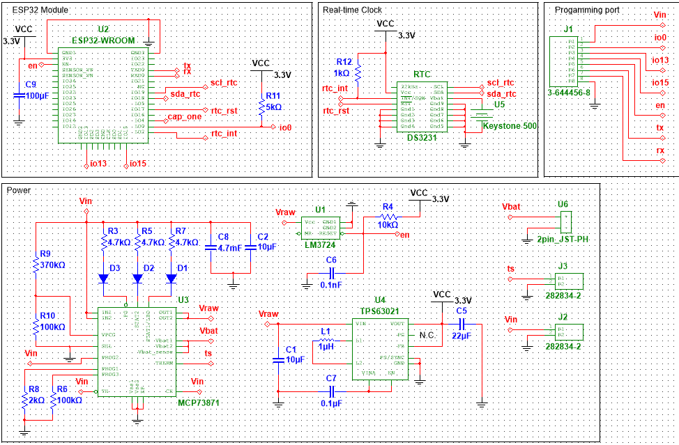
- Utilizes an ESP32 as the microcontroller
- Code will be written in C using Espressif's ESP-IDF
- Sensor transmits data over ESP-Mesh network
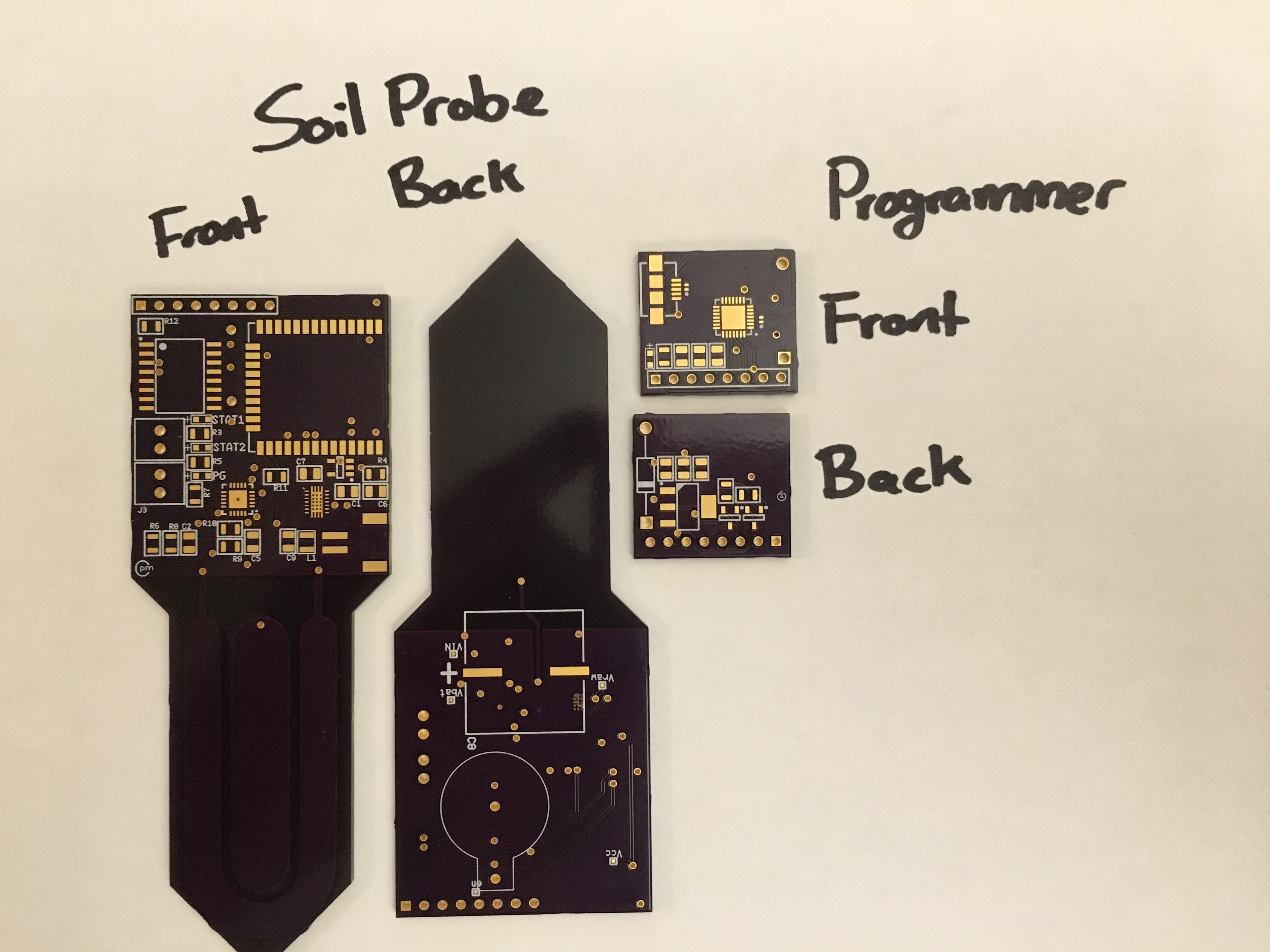
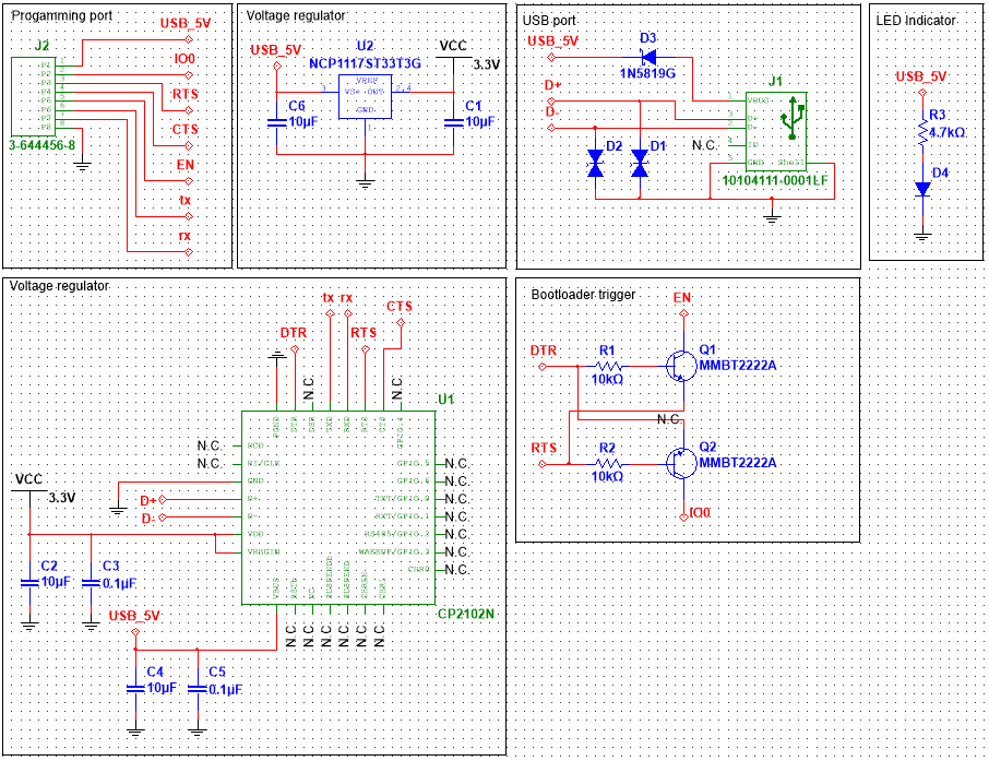
- Board will be programmable with a daughter board and micro USB cable
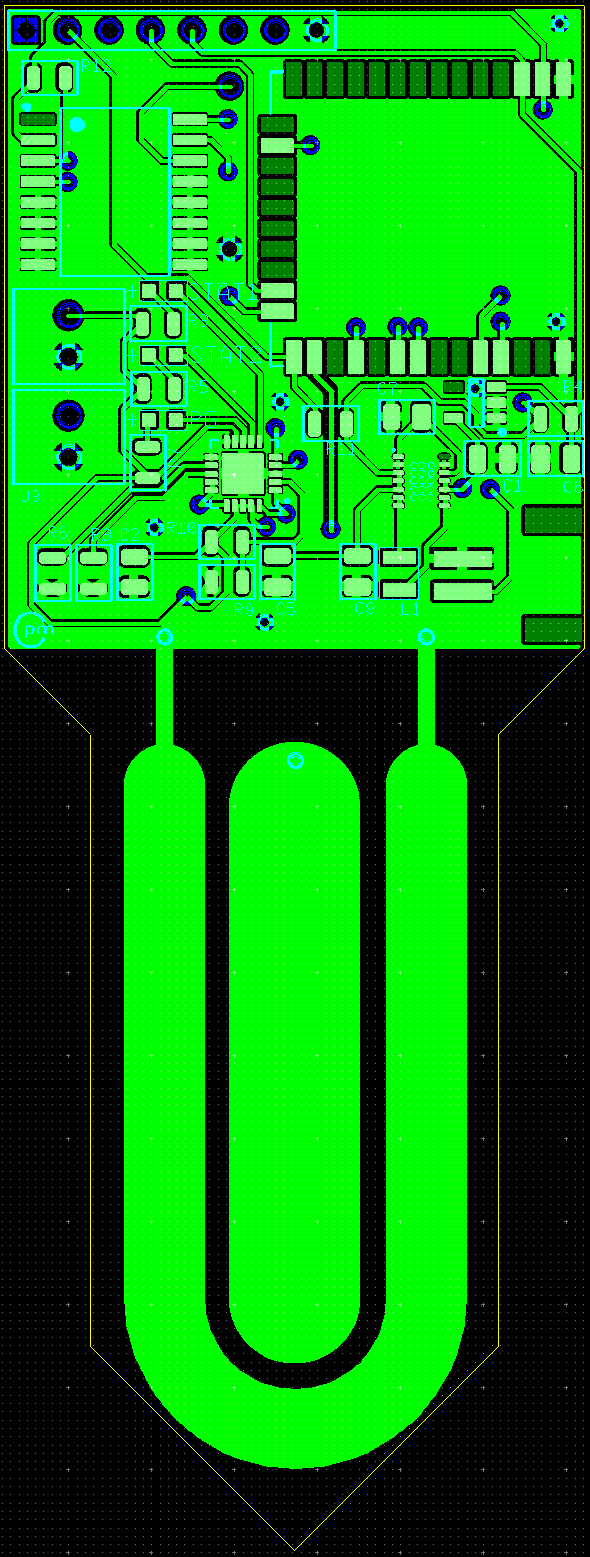
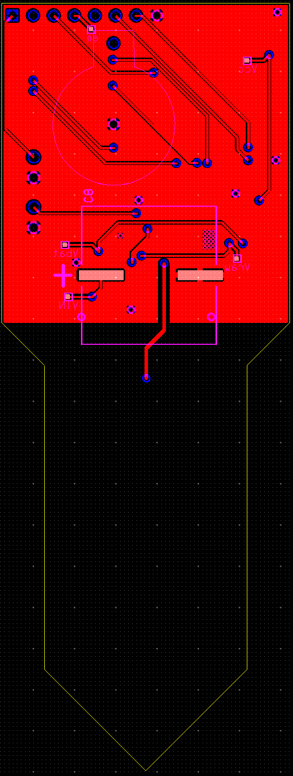
- Soil moisture will be calculated by measuring the soil’s dielectric permittivity instead of resistivity
- Will use capacitive touch sensor on ESP32 to measure the changes in permittivity
- Circuit powered by a small rechargeable battery recharged by a solar cell and managed by a solar charger component
- Planning on using the BQ24210 Solar Battery Charger
- A real-time clock (RTC) chip with alarm function will be used to wake ESP32 to transmit data
- Planning on using the DS3231 RTC
- Can use RTC's thermometer to measure environment's approximate temperature
- Planning on using the DS3231 RTC
Testing Plan
- Initially prototype and breadboard with ESP32-DevKitC
- Test ESP32’s capacitive touch sensors ability to detect soil moisture
- Interface ESP32 with RTC chip over I2C and test sleep and wake functionality
- Ensure that final device can measure and send data over a wireless connection
- Measure final device’s current consumption when device is both awake and asleep to calculate sensor’s battery lifetime
- Use data to pick optimal battery size and possible time intervals to measure and transmit data

 Michael O'Toole
 Torbjörn Lindholm
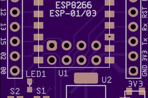
 drewrisinger
 Miroslav Zuzelka