 Foxchild
I am looking for people who would like to help me expand this project!
- STM32 Firmware Developer
- Super Nintendo Firmware Developer
- Modelling for 3D Printing
- Audio Electronics Stuff
A cartridge for the SNES (Super Famicom) that uses the built-in wavetable chip to finally turn the console into a synthesizer!
Already have an account? Log in.
To make the experience fit your profile, pick a username and tell us what interests you.
I am looking for people who would like to help me expand this project!
05F4424A-10F0-40EF-84CE-B289995F3D8B.mp4short demo videoMPEG-4 Video - 14.94 MB - 09/05/2019 at 20:40 |
|
Took me a good evening but I finally sat down and drew a shell for the SnesDrone board in Tinkercad. It features holes for the PCB mount potentiometers of the new PCB design and it SHOULD fit into NTSC and PAL consoles. Haven't tested this yet due to a lack of an NTSC console though. :D
In case you want to print this, here's the link to the tinkercad project: SnesDrone Tinkercad Shell
As you can see in the new profile picture to this page, it prints pretty well!
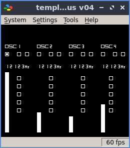
The basic functionality seems to be working, finally! :)
This means, four oscillators (in the SNES DSP) are producing a constant sound while frequency and volume can be changed with the potentiometers connected to the cartridge. The GUI is just a still image at the moment, but it will display some information regarding the four oscillators and also the user will be able to change waveforms and effects from the GUI.
I am working on the second iteration of the PCB at the moment which will feature PCB mount potentiometers and also 3,5mm audio jacks for CV input from other synthesizers. These CV inputs may be used for AMP CV or Pitch CV in the future. Also the potentiometers might be mappable from the GUI. We'll see about that... It all depends on whether someone other than me is interested in these features. :D
When the second iteration PCBs come along, and the housing is done too, I will give some devices away for cost of the parts, which is about 20€. If there are any willing testers out there I might even have some devices for free.
Cheers,
Michael
Looking at things while listening to stuff rules.
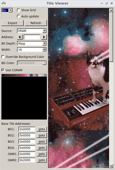
That's why I spent some time beside the project to create this little tool called SNES GAPE which lets me translate any picture into the SNES' graphics format.
It's called SNES GAPE firstly because it's a "graphics and palette enabler", and secondly, because the graphics format of the SNES is a gaping sneshole.
Output ooks like this for instance:
This is the debugging view from inside and emulator where I loaded the picture as a ROM image.
If anyone cares, you can get this tool and the code here: snesgape github
Obviously this is open source and not only are you free to use and change this software, I would even love you for it.
Cheers,
Michael
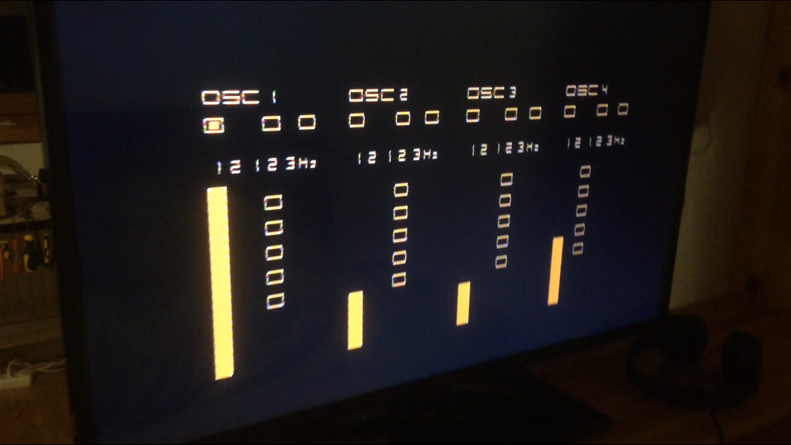
Just to let you know, the project is still going. I just had to finish a university thesis. Also, the SNES DRONE is now officially my next thesis, which is good because it gives me much more time for this.
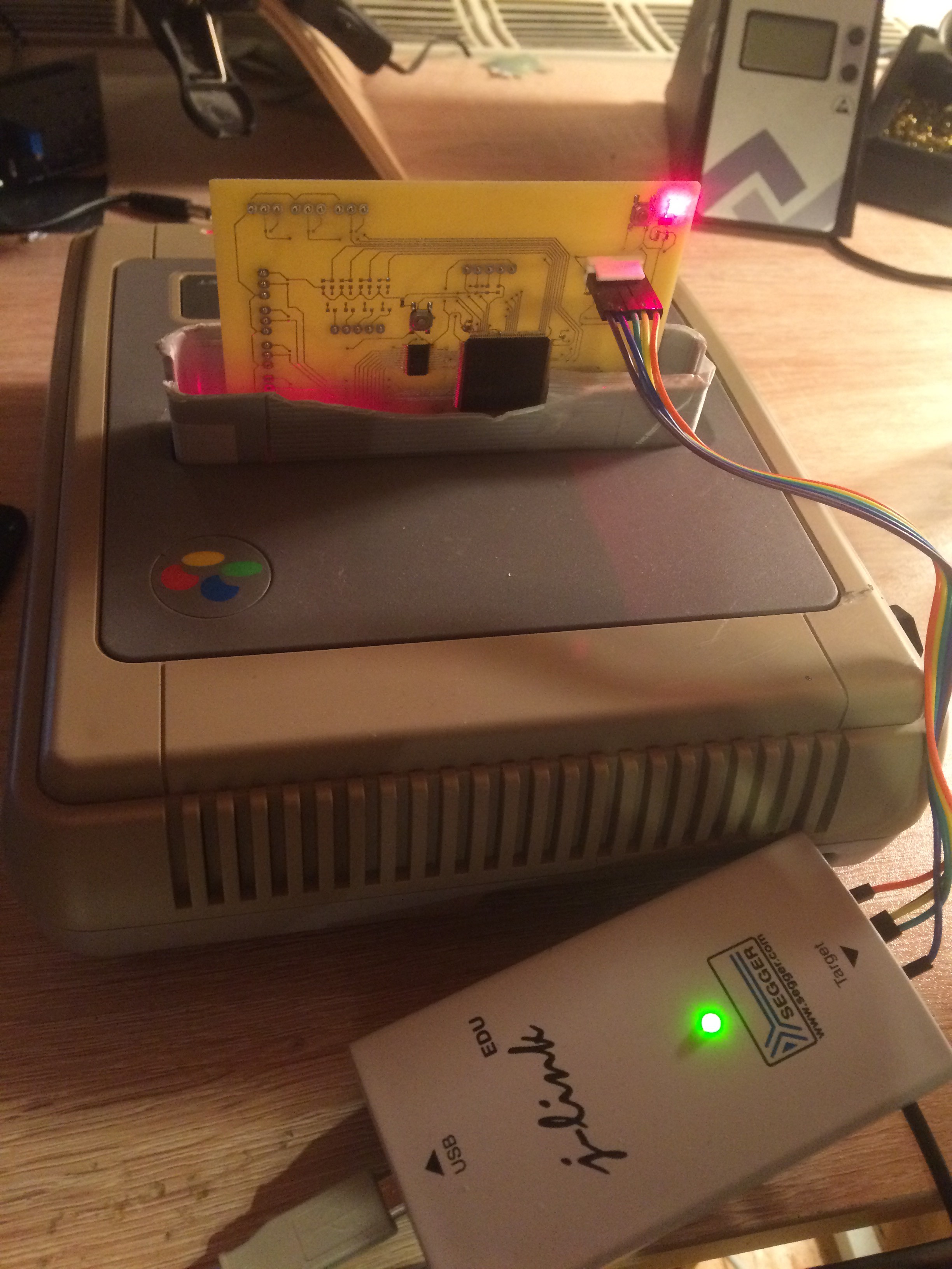
As you can see in this picture, development hasn't stopped either. I have control over four oscillators now and at the moment I am working on the GUI, which will be controlled by SNES joypads.
The software is available as a ROM file (even though you won't be able to use potentiometers, duh): https://github.com/hirschmensch/SNESDRONE-emulation
The revised hardware will go into production in june, maybe then I'll have some schematics for you.
Cheers,
Michael
Just a quick notice that the project has stepped over a huge milestone today: I had my first sinewave output! <3
It‘s just a short sample of 1k sine but damn... feels good man! :D
This means the project‘s next milestone is to run the SNES firmware code from RAM and fetch for potentiometer values every other millisecond to change the frequency.
I will also post hardware documents for the cardtridge in the following days. I just have to make some minir changes because of course the first design has mistakes...
I will also have a giveaway of another prototyping board I developed in case anyone‘s interested in rolling his own SNES code.
Stay tuned, SNES DRONE is coming!
cheers,
Michael
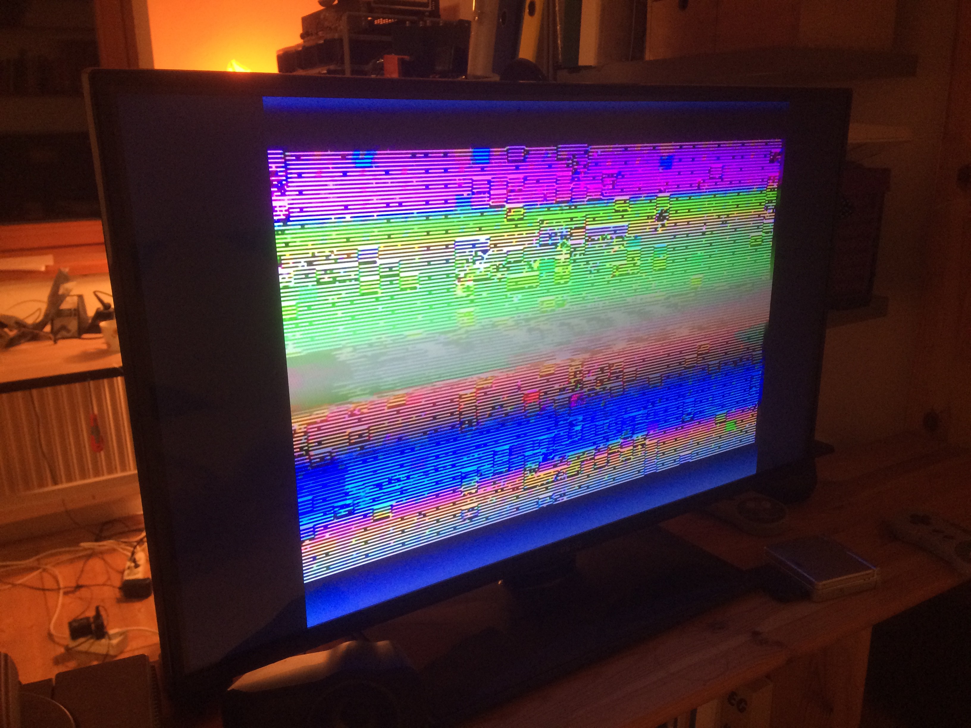
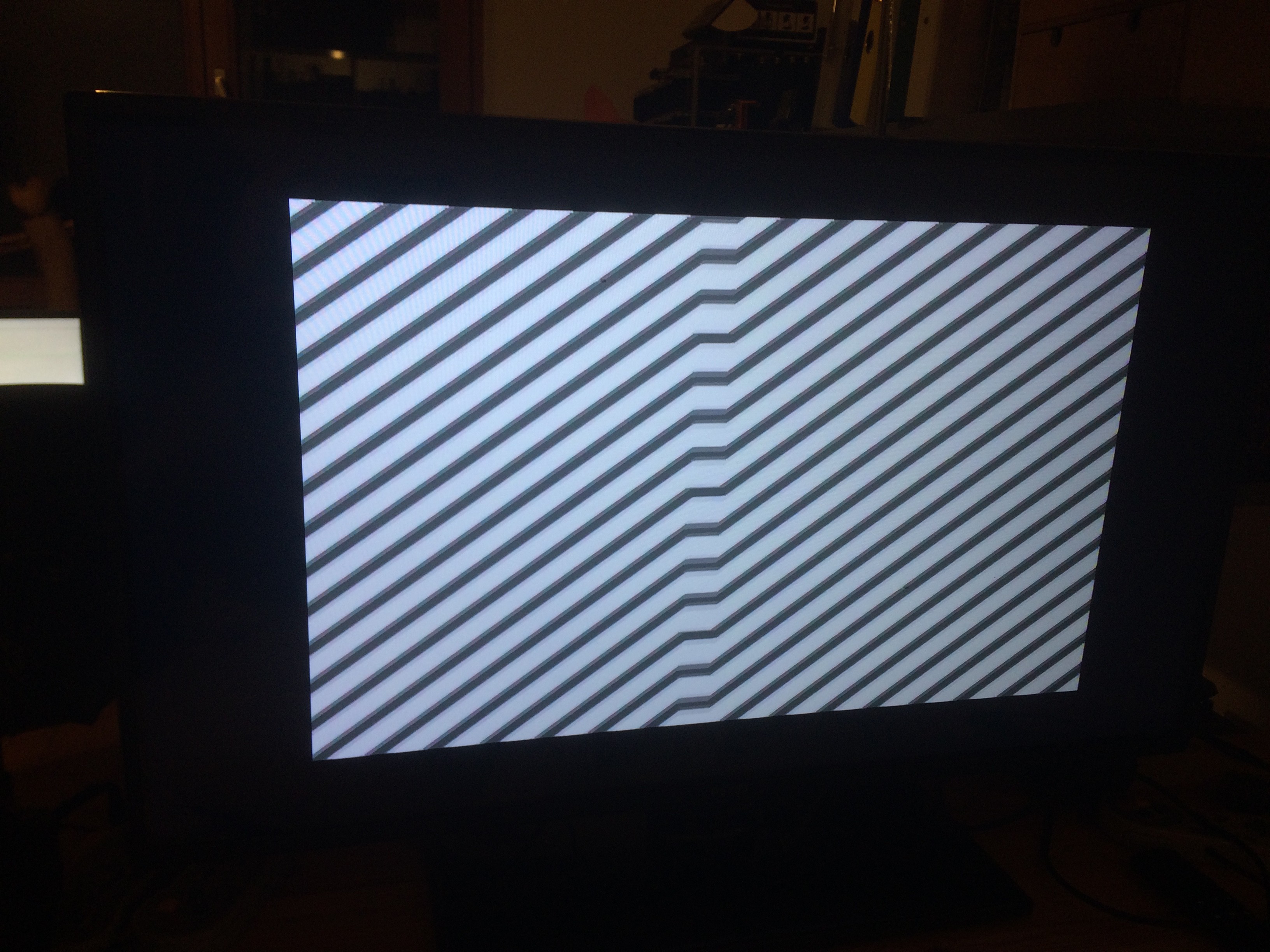
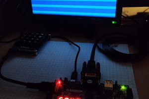
Made some minor changes to the STM32 firmware today and was finally able to test some real-life code for the SNES. It's a small set of instructions that's supposed to color the screen completely green. This screen isn't green, I know that. :) But it's not too far off!
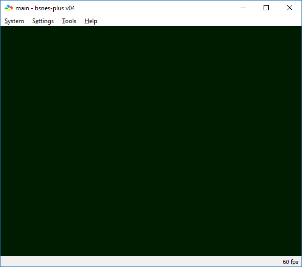
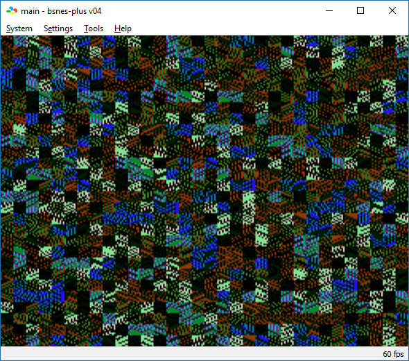
If you look at this output of bsnes, you can see what I was expecting to see:
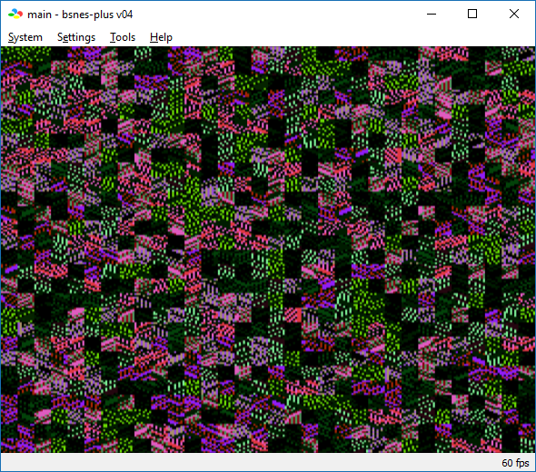
But I did not write or invent this code, and if I load it in bsnes with accuracy mode, it looks like this:
And after a reset it looks like that:
So, I think it's safe to say that the pitch green image is a product of emulation errors because a more accurate emulation also shows a random image.
Going to test a sound sample next.
As I said, it's an interesting world where a picture like this can be considered success. :D
cheers,
Michael
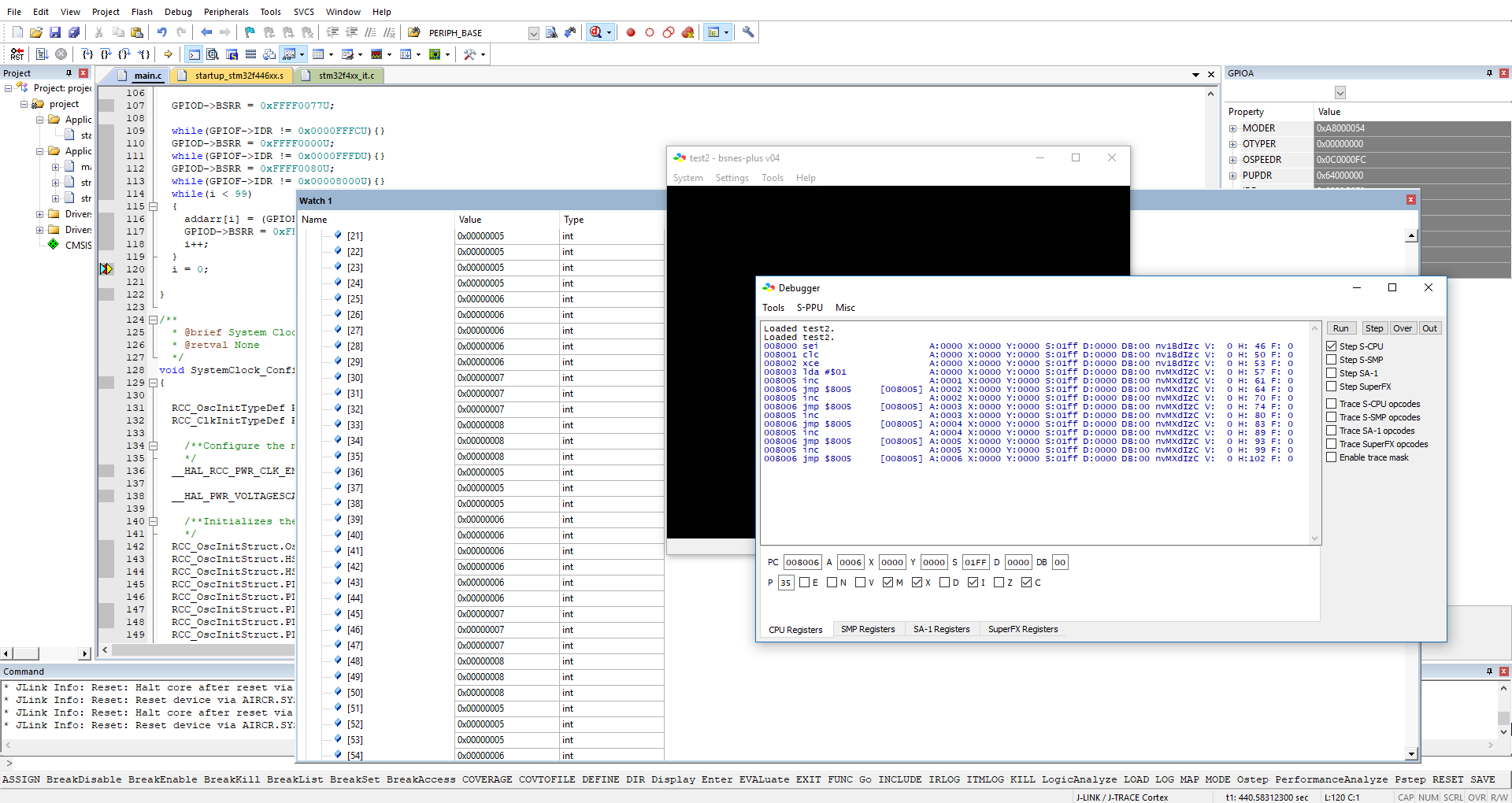
Today, I executed the first line of code on the SNES which was actually stored in an array in the firmware for the STM32! Felt like landing on the moon tbh. :D This means, a very important part of the firmware is done and working. I am now able to store 65816 instructions in the STM32 memory and have them executed on real hardware.
Coming up is firmware for the SNES to get some sounds from the SPC-700! Stay tuned!
Cheers,
Michael
So, as promised, we're going to write our first SNES program today. There are many tutorials out there for SNES code in assembler language, but we're going to do things a little differently today: We're going to write bare-metal machine code right away!
Tools needed:
We'll have to use bsnes+ because it's emulating hardware and it's not focused on playing SNES games. Emulators like 9snesx will not work because they ommit certain hardware "features" (and bugs). The bsnes+ emulator simply takes machine code from a binary file and feeds it to a virtual 65816 processor in a SNES machine. bsnes+ also emulates SPC-700 and other chips in the SNES. To write our first program we have to understand at least a little bit about memory mapping in the SNES. Unlike processors of today, the Ricoh 5A22 (65816 core) does not have built-in memory. It has a 24-bit address bus and an 8-bit data bus, and everything is connected to these busses. Even the internal system registers. So, the ROM, the RAM, the GPU... everything is connected to the address bus and seperated into address spaces called a "memory map". To talk to the ROM, we have to use the correct address space.
As you can see in the Memory Map of the SNES (https://wiki.superfamicom.org/memory-mapping), ROM is located at Banks 0x00-0x3F on addresses from 0x8000 until 0xFFFF. So the ROM is located on 64 banks of 32768 bytes each. 64 times 32768 equals 2097152, which equals to 2MB. There are ways to address much more space on the SNES, but for now, we don't care about this.
A bit about the ROM model on the SNES:
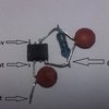
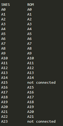
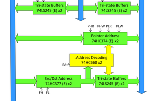
There are two typical types of ROM for the SNES called LoROM and HiROM. I will only focus on LoROM. LoROM causes ROM chunks in SNES to be max 32KB wide ($8000 bytes), and are typically fetched from the $8000-FFFF region. It is produced by connecting the address lines like this:
So for addresses from 0x000000 up to 0x007FFF everything works "normal". Since A15 is not connected, the adresses from 0x008000 up to 0x00FFFF refer to the same area. Same with the banks. Since A23 is ommited, the ROM can only distinguish between adresses in the banks from 0x00 up to 0x7F (128 banks) and the banks from 0x80 to 0xFF refer to the same area. So the ROM is repeated once in every bank and the upper banks repeat too. But if we take SNES signals A16 to A23 (the bank lines), we can see that A16 is actually connected to A15 on the ROM. So the SNES counts the addresses from 0x000000 up to 0x007FFF, everything is cool, then it counts from 0x008000 up to 0x00FFFF and actually sees the same data. This means the ROM is now at address 0x007FFF.
SNES                 ROM

0x00:0000 -
0x00:7FFF           0x000000 -
                    0x007FFF
0x008000 -
0x00FFFF
Now the first bank bit increments and the SNES is at address 0x010000. The ROM actually sees this as bit 15 and reads the following address:
0x000000010000000000000000b: SNES 0x010000h
0x000000001000000000000000b: ROM  0x008000h
SNES                 ROM

0x01:0000 -
0x01:7FFF           0x008000 -
                    0x00FFFF
0x01:8000 -
0x01:FFFF
So, since one bit (A15) was left out, the ROM gets mapped twice on the SNES and has its own address space. This concept works for banks up to 0x1F, then things get a bit more complicated, but I wouldn't worry about it too much right now. One more important thing is that ROM is only visible from SNES addresses 0x008000 to 0x00FFFF, because the lower half is used for other things.
O.K., now back to our ROM file. The file needs a block of specific information which includes the internal name of the ROM, the interrupt vectors (addresses to machine code within the ROM in 16 bit format), version, etc. This portion of the ROM is also known as the SNES header. While the name of the ROM and certain region locks are not important, because they are only tested by software...
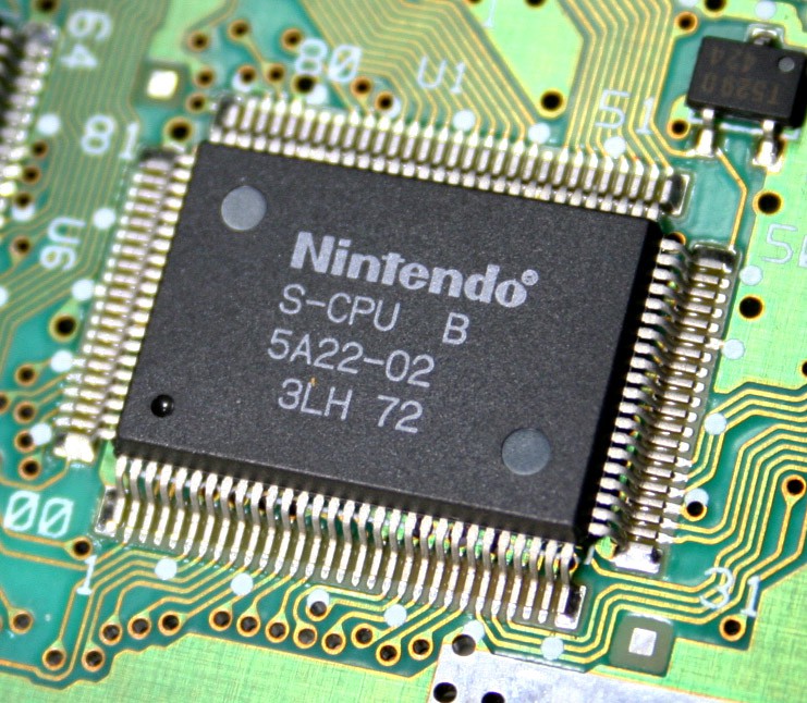
Read more »Let's start from the top here and work our way down... The CPU in the SNES is the Ricoh 5A22.
The 5A22 is a Microprocessor, so it has a CPU and peripherals. In addition to the 65C816 CPU core, the 5A22 includes:
The 65816 core is an enhanced version of the 6502, which is an 8-bit core. So, 65 in the name means it's compatible to the 6502, and 816 means the possibility to switch between 8- and 16-bit register sizes.
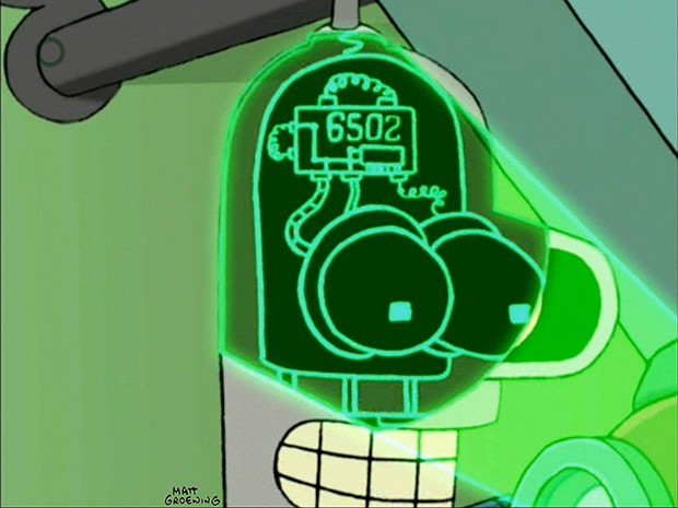
So, in the beginning there was the 6502. It's used in personal computers and consoles such as the Apple IIe, the Commodore PET, the Atari 2600, the Commodore 64, the original NES and Bender from Futurama.
Then, there was the 65816, which was an enhancement with higher clock rates and bigger register sizes. It's used in the Apple IIG and the SNES.
The 65816 is (almost completely) backwards compatible with the 6502 and even has an emulation mode that is automatically initialized when the processor is powered up.
So, to understand the 65816, we need to understand the 6502, and luckily, many many people have spent lots of time doing so. There's even this visually animated emulator for the 6502: http://www.visual6502.org/ It only exists because Michael Steil took the lid off of the 6502 and actually made microscopic photographs of this legendary device. He did a talk on this work and you can watch it here: (bottom)
When I learned that the SNES CPU is actually an enhanced 6502, it was even more reason for me to do this project because I often fantasized abpout programming a 6502 in real life. :) Programming doesn't get anymore "bare-bone" than 6502. ;) So, the 65816 takes opcodes which you can find in tables, but most people used to program this chip in assembler which is then "assembled" to opcodes that are directly readable by the processor. These machine codes are stored in external memory, because the 5A22 has no built in memory. This external memory is actually just the cardtridge! When the 5A22 is powered up, it loads the first adress on its 24-bit adressbus, this bus is hardwired to the ROM, which reacts and presents the first opcode for the processor. After processing the first command, the processor now wants another operand or increments the program counter to read the next command, which again is presented on the adress bus and the ROM reacts and puts data on the 8-bit databus. So, this is exactly the bahaviour that we will have to simulate for the processor! Doesn't sound too complicated, right? Read an address, look up the data on this address and present the data! Well... turns out it's actually really that easy! :D Yeah well almost, as you will see.
Someone has actually already done something similar with an ARM processor. You can find this project here: https://dhole.github.io/post/gameboy_cartridge_emu_1/ It's really interesting and you can already see some problems that we will encounter much later in this project.
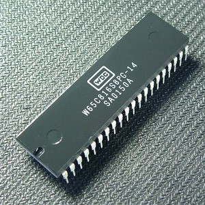
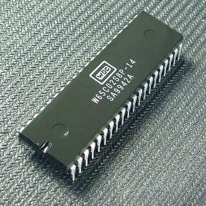
If you want to read more about the 65816, such as the opcodes or other technical details, I can recomend this page on the superfamicom wiki: https://wiki.superfamicom.org/65816-reference
They also link to datasheets by Western Design Center (WDC) for...
Some basic investigation whether a project is even possible to realize is obviously mandatory if it's something you've never done before. Most of the times I get stuck in this phase though, so this time I wanted to limit myself to essential things and not research too much (which turned out to be a good idea).
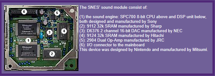
In this first part I want to talk about how sounds on the SNES are created, but don't worry, this one is going to be a short one. :)
Most of the work is done by the synthesizer chip - the SPC-700. This is actually already a co-processor for the main CPU on the SNES. It runs at roughly 1MHz, has access to 64KB of memory and has 4 8-bit I/O ports to transfer data to/from the SNES. The sound is composed of 8 channels of compressed sample synthesis in 8bit resolution. This means, the SPC-700 laods a short sample of audio into one of the 8 channels and then it reads from its own program memory what it's going to do with this sample. At the most basic level, it's going to repeat this one sample in an infinite loop, so if you store a sine wave of 1kHz in a channel, you're going to hear a sine wave sound at 1kHz. So, to "play" this sound musically, the SPC is also able to "tune" and "pitch shift" this sample. Together with an envelope shaper with paramters such as attack and release, it's already possible to mimic simple instrument sounds like on old 80s keyboards.
If you want to know more about wavetable synthesis, I can highly reccomend this short video about the basics: (it's attached at the bottom)
So basically, the SPC-700 needs samples and instructions to generate music. Turns out, there's already a small scene of people out there who build little devices to play such programs which are extracted from SNES ROMs. It's awesome! Check it out right here: http://snesmusic.org/files/spc700.html
But the APU (audio processing unit) of the SNES not only consists of the SPC-700. There's also a little DSP (digital signal processing) chip involved. When I said earlier that the SPC-700 is doing the pitch shifting, I was actually lieing (for simplicity reasons), because the pitch shifting is actually done by this DSP. It also has some neat features like echo effects and a white noise generator which will come in handy much later if we want to produce some rhythmic sounds. The DSP is accessed through the SPC-700, which makes the whole thing a little bit more complicated. But since both chips are fairly straight forward (I hope), everything will be fine... ;) Well, the SPC-700 has two registers which are directly wired to the DSP. So one register holds adresses for the DSP and one holds instructions.
Accessing both the SPC-700 and the DSP, again, is done through the main CPU. So next post will cover one of the greatest CPUs of all time: The 65816! If you've never heard of it before, I can tell you it's not much more than a 6502, which was the chip in legendary computers such as the Apple II, the Commodore 64 and the original Nintendo Entertainment System! <3
In the last part of "Is it even possible?" we're even going to write a little ROM file that generates sound and works on an emulator, so stay tuned!! This was the first time that I wrote my own ROM file for a vintage gaming console and I can tell you it's quite fascinating! :)
Oh and in case you want to check out some more in depth information on how sound on the SNES works, check out these technical documents: https://wiki.superfamicom.org/spc700-reference
Cheers,
Mike


Very cool! Glad you found this project!
Well, even though the SnesDrone is producing sounds, it's not ready for music production I'd say. I have a bit too much jitter on the frequency values still.
I am planning on utilizing the sampling capabilities! I have written a bit-rate-reduction algorithm that's able to run on the MCU and would be able to take samples from the ADC and turn it into SNES samples. I would also like to implement CV inputs so some parameters could be controlled from external LFOs for instacen. But best case would be some time next year to implement this. There's just too much stuff I want to do before... like for instance using all the available effects in the DSP. There's so much potential in this thing. :)

I love this and would be honored to test this project whenever. I'm a huge synthesis/DIY electronics geek and a longtime fan of computers, consoles, and everything chip. I'm also a musician. I would be looking at the thing from mostly a musician's perspective -- and a little bit of software perspective as well. Let me know if you're interested in sending me one of the PCBs.
Love this, would use this big time in my home studio, love to test it for you,
Hey! Great to hear that you're interested! I will definitely be shipping free devices of the alpha release to testers and developers. The new revision of the PCB is going into production as we speak. Do you have a NTSC or a PAL device?
Hey, Foxchild, i have a NTSC USA SNES, fell free to email me if that helps
fixingmytoys.thx1138eb@gmail.com
Justin

looks pretty nice. Is there technical docs on how you incorporated the mcu (assuming the big IC is one) on the board, and where the ROM is stored, if one is needed to run anything on the SNES itself.
yes of course! :) I will upload it all in the next days and weeks.
There's actually no ROM on this cartridge, I just use the 512k of flash on the STM32F4 because I don't intend to store complete games anyway. But it'll become clear when I start the log... Glad to hear that I caught your attention! :)

 Mad Ned
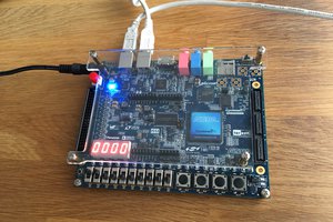
 ErwinM
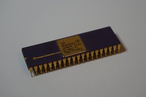
 Erik Piehl
Hello! I've been searching for a little while to see if anyone has tried to utilize the snes/super famicom for music creation and found you! I think this project is super cool and I appreciate your ingenuity. Are you planning on trying to figure out how to utilize the sampling capabilities of the spc chip? I've been dreaming of being able to utilize the Snes like a hardware sampler :) . Anyways, please keep up the good work and know that it is appreciated!!