 Ken Yap
Sometime back in a promo I got a few USB port LED lights for about a dollar. They are remarkably bright, demonstrating how much LED efficiency has improved over time. I saw that on eBay LED strips are about a dollar a metre, so they have got much cheaper too. The strip holds SMD LEDs, grouped in 3s, with a current limiting resistor in each group. The bus voltage is 12V. Specs say they draw 4.8W/m which means 400mA. Since there are 20 groups/m this means the LEDs are run at 20mA. Brightness control is by pulse width modulation. The strip can be cut to length between groups.
These should not be confused with Christmas LED decorations. These are far brighter and intended to provide LED lighting. They come in various colours, plus warm and cool white. The coloured ones are for effects or for mixing RGB to get desired colours. I opted for 5 metres of cool white to illuminate my kitchen counter.
To control the brightness of the LED strip I opted for an old school PWM generator based on the venerable 555 timer. Why? The main reason is memory. The position of the potentiometer remembers the level you left it at before you turned it off. If I use a MCU, I will have to arrange to retain the level in non-volatile memory when powered off.
Of course if I were controlling multiple strips, wanted ramp effects, or more sophisticated features then a MCU would be appropriate. I would use a rotary encoder to generate the digital pulses to increment or decrement the level, and use the push switch to select a strip, thus not having to convert from analog to digital. I would probably also attach a display to indicate the selected strip and brightness setting. This would be a straightforward MCU project and almost any MCU would be up to this task.
I wanted to keep the frequency roughly constant for all levels. I found a clever circuit here. It uses a 555 timer in astable mode. I have modified a little and redrawn the circuit in Kicad to avoid any copyright issues posting the original image.
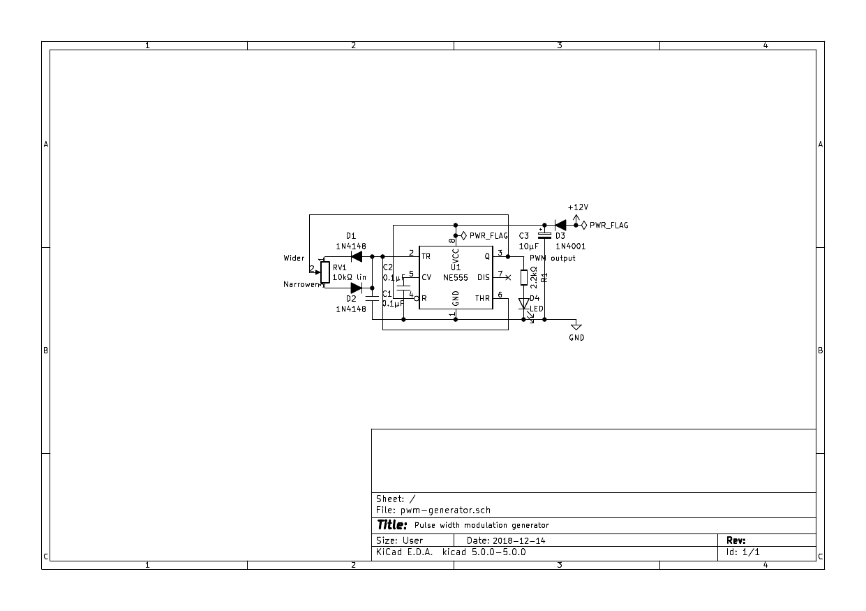
The charge and discharge paths are routed through steering diodes to both sides of the wiper of a potentiometer. Since the period is proportional to the sum of the resistances on each side of the wiper, which add up to the total track resistance, the period and therefore the frequency are roughly constant at all positions of the wiper. The values chosen make the astable run at about 1.3kHz, high enough not to generate visible flicker. The power diode and capacitor, and the bypass capacitor are needed to prevent power supply noise generated by switching the large currents from affecting the 555 trigger point. In an earlier prototype, their omission caused the 555 to turn on prematurely at low levels making it not possible to dim the strip totally, even though this worked on just the pilot LED. The pilot LED and current limiting resistor are optional; they are for debugging.
The PWM generator feeds a CMOS power switch module intended for such applications and costs about a buck on eBay. This tiny switch module handles a whopping 15A, far above the needs of 5m of LEDs which only require 2A. The CMOS power transistor has low on resistance so hardly any heat is generated. They are almost ideal switches.
If you prefer to roll your own power switches, maybe because you have the power transistors handy, try this page. It talks about RGB strips but the principles are the same.
12V can be obtained from various sources. I have power bricks for external hard drives that are suitable. An old PC power supply would also do.
Details of mounting the LEDs are specific to my situation so I'm declaring this project completed.

 Theo
Theo
 icstation
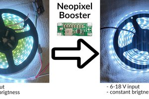
 Jan Mrázek
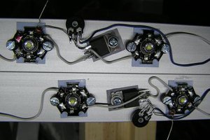
 Yann Guidon / YGDES