 Francisco Piernas
***Safety First***
This machine is very dangerous. I would not recommend it's construction unless you know what you are doing.
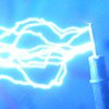
To avoid any risk, I set a countdown and leave the machine alone until the job is done. I do have a Geiger counter to make sure I'm not receiving x-rays. The hand picture was only done once and for half a second of exposure :P
Introduction
This project started with a question one day taking a shower: can I build a decent X-Ray machine in the garage? I quickly found the answer, no. At least, not with what I knew or could make. I had to spend like 2 years (I was also studying physics at college) to improve my skills and knowledge.
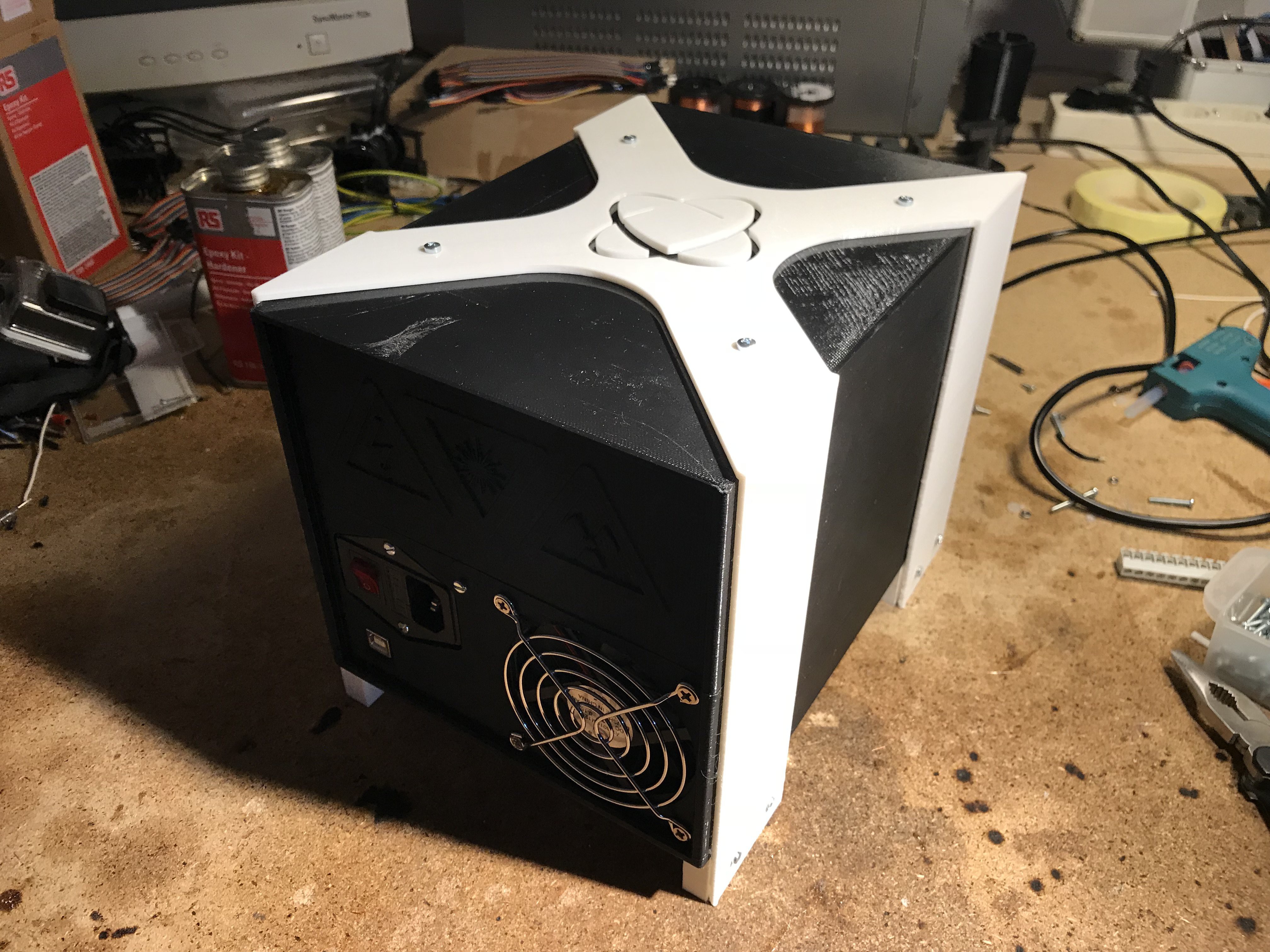
Finally I started designing the whole housing with Autodesk Fusion 360, limited by my 3D printer's area. I wanted to design a powerful machine, and I wanted it to be plug and play, so the power supply would have to be inside. I had to think a lot how to put inside that housing every single part of the machine, this was an absolut hell since I was limited by the size of my printer.
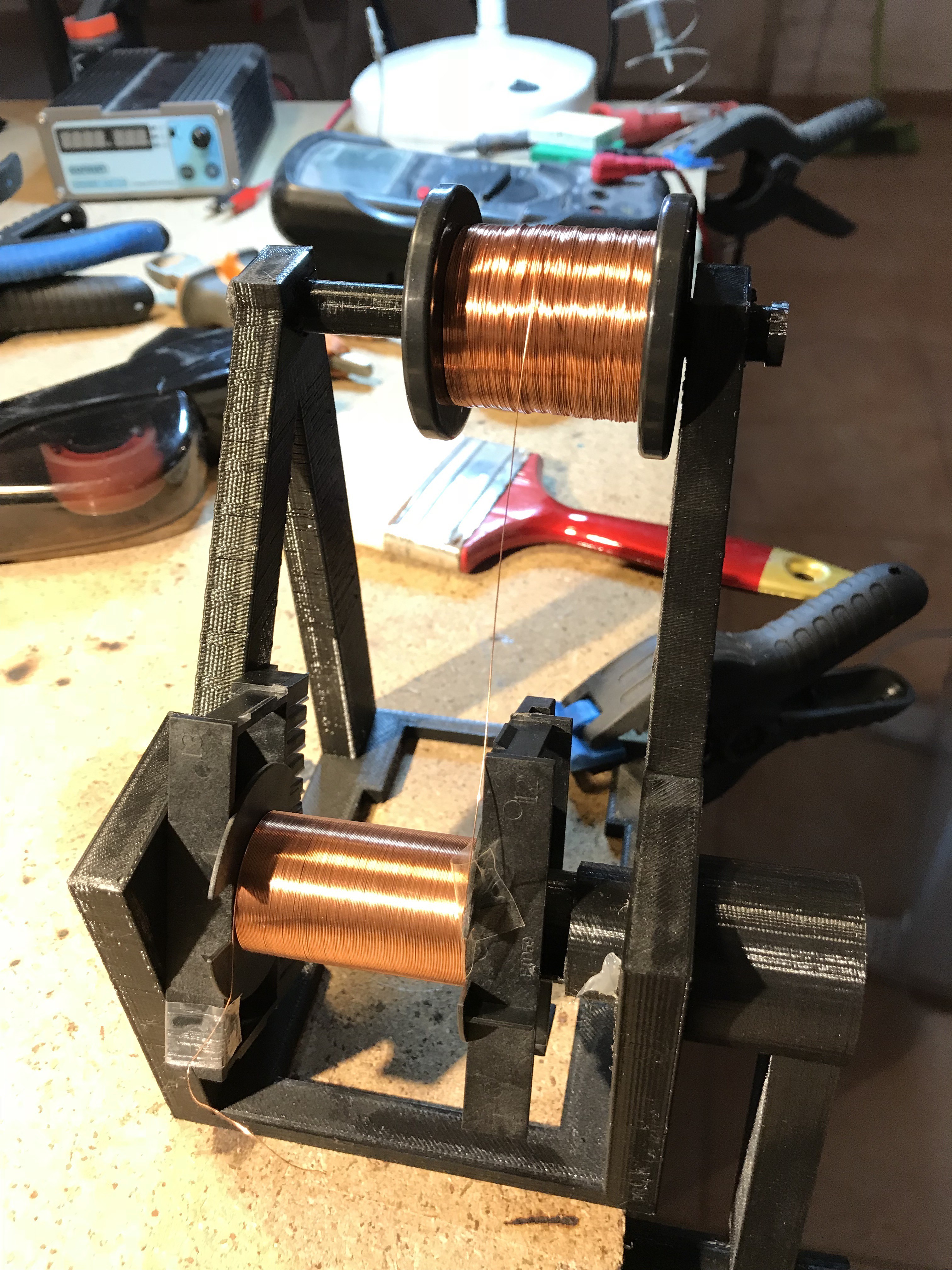
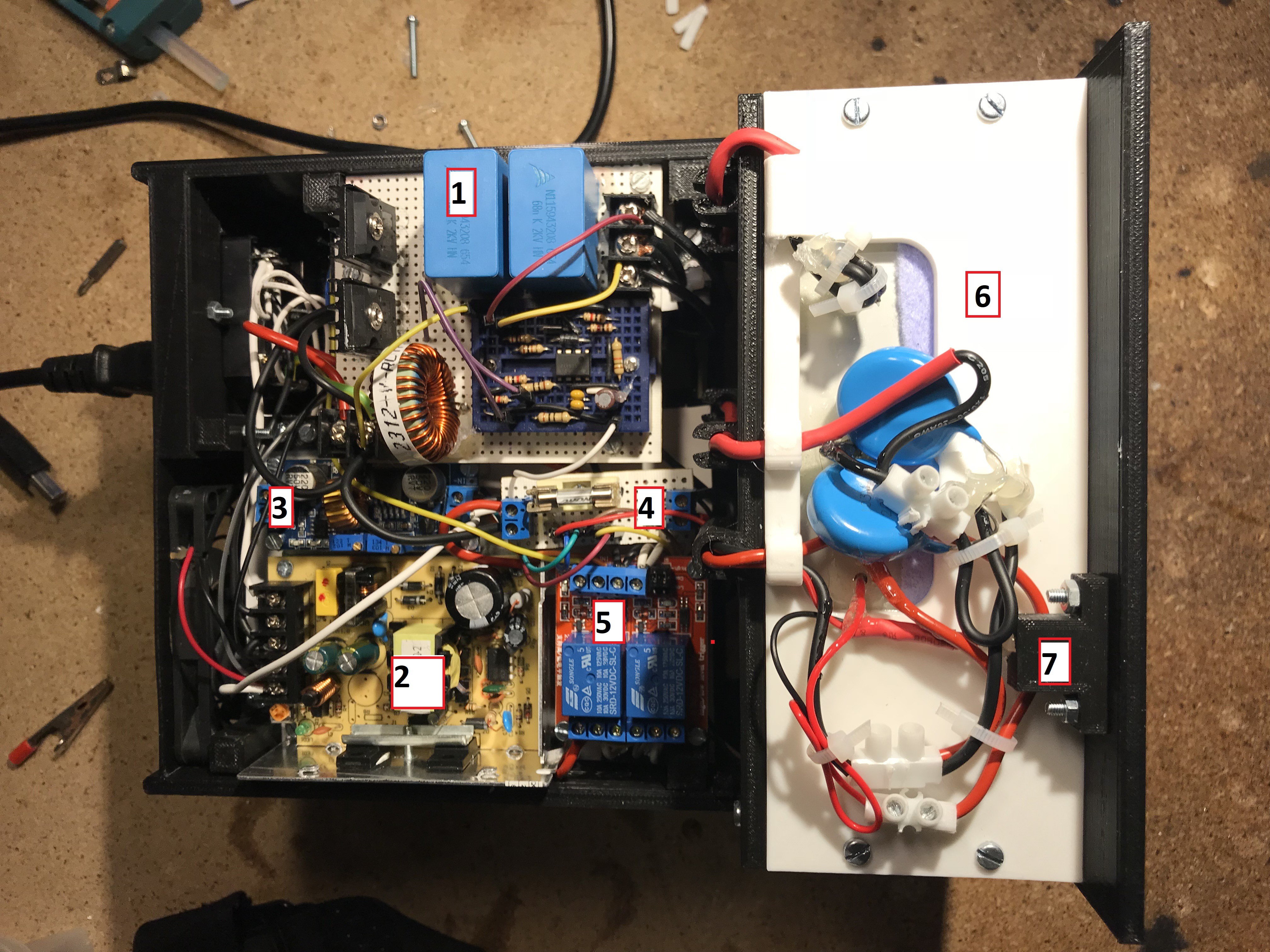
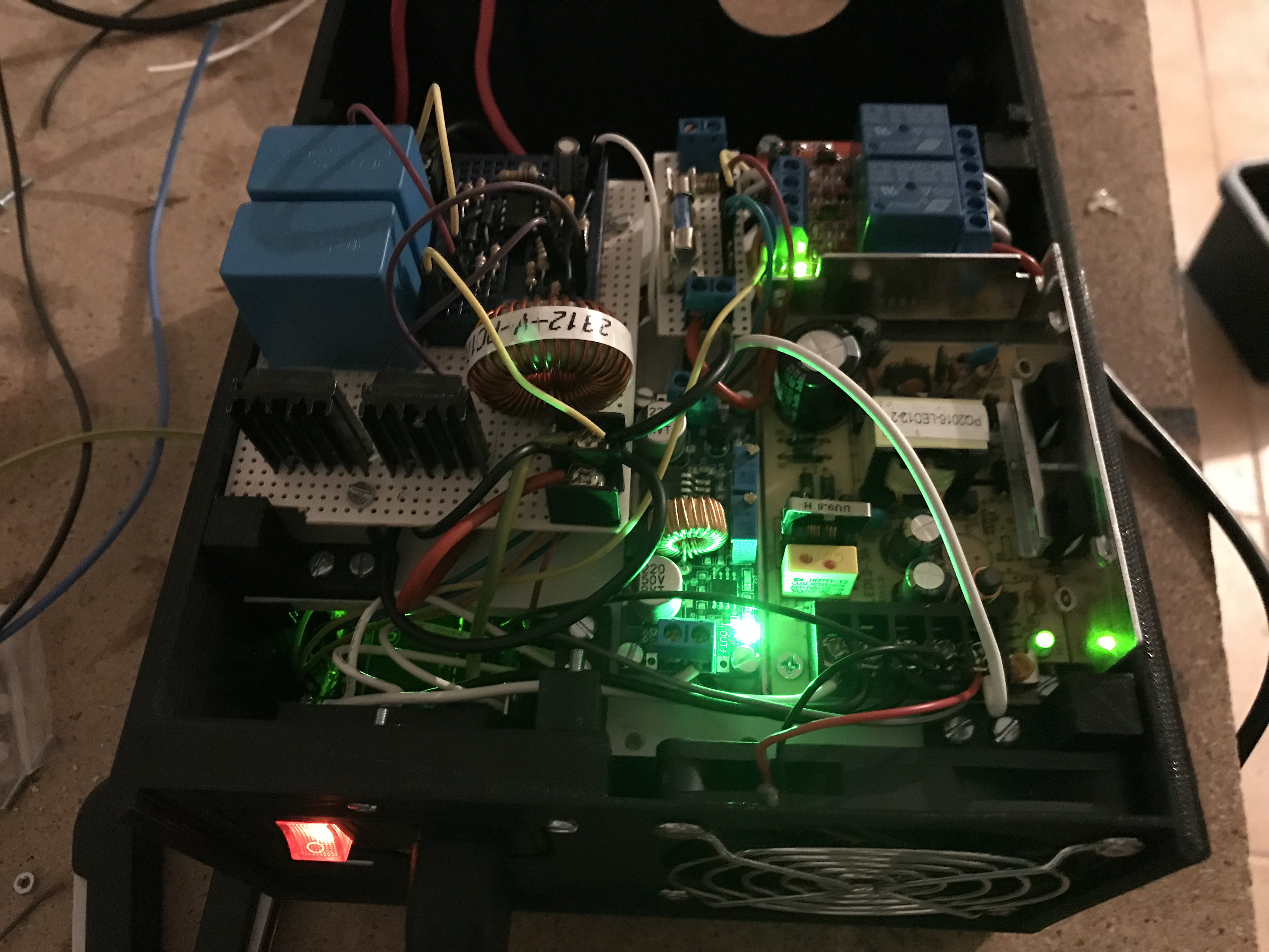
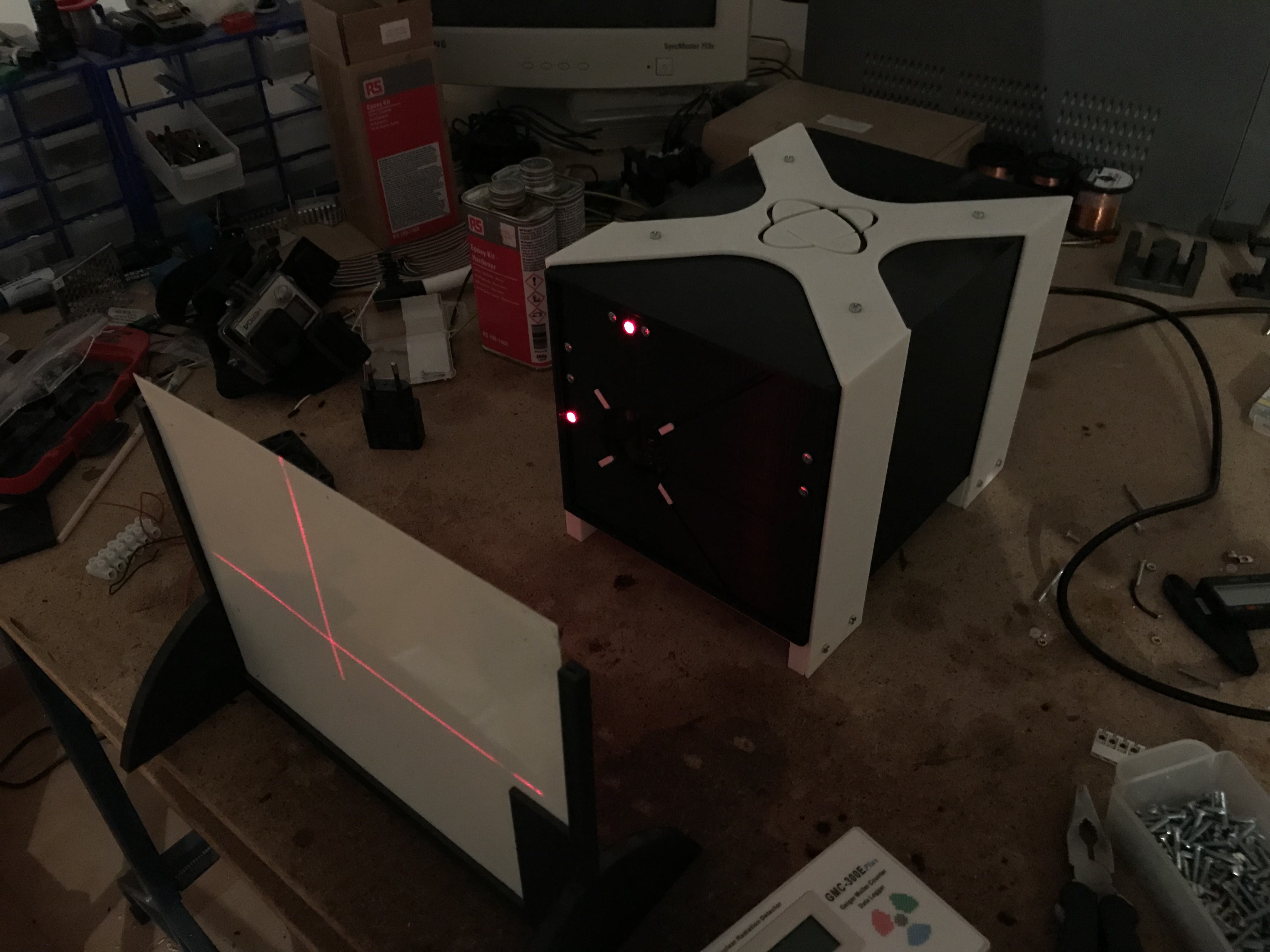
To solve that problem, I decided to make two levels inside the machine. The first level would contain the main 48V PSU, the Arduino board and the high voltage transformer. The second level would be above, containing the ZVS, another 12V PSU and a step-down converter for the tube's filament. The waterproof box that contains the voltage multiplier and the tube would be at the front of the machine occupying both levels. The machine has no buttons. it's controlled via USB, using the Arduino IDE's monitor to send commands to the machine.
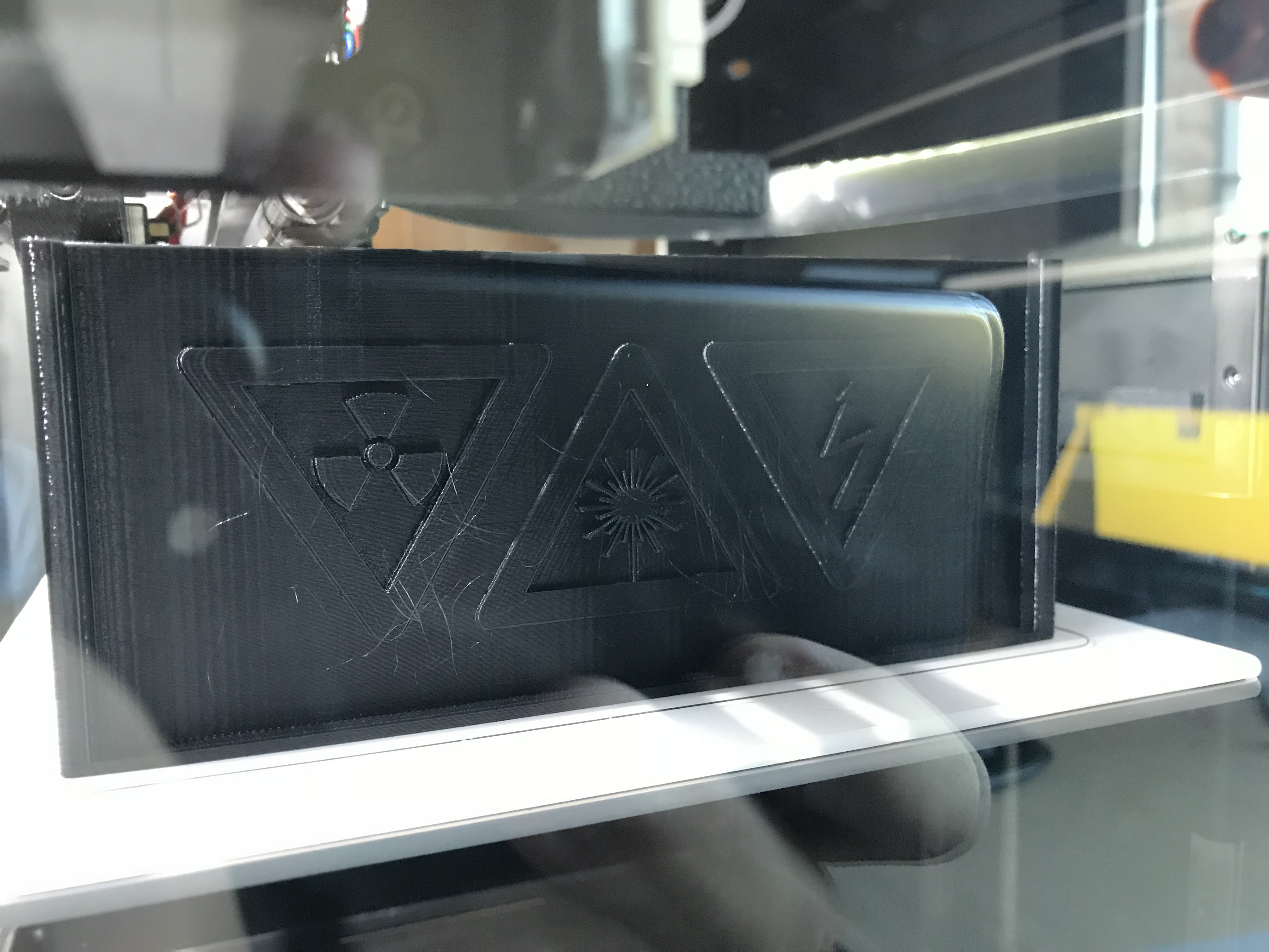
Also, because this machine is my final degree project at college, I wanted it to have my college's logo on it, the one shown on top.
The machine is very powerful but probably not as powerful as any professional unit you can buy. Well the idea was to just learn how to make one and that is checked.
I also recorded most of the design & construction process and made a short video:
If you want to see two live tests, see the file "tests.mp4".
Note: this project contains my subproject https://hackaday.io/project/162935-piernass-fast-zvs-mazzilli-driver


 sandy
sandy
 Setvir
 Renze Nicolai
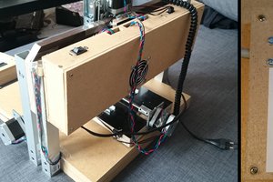
 joekutz
Will you be sharing the Code for the Arduino?