 Quinn
QuinnThis project is documented in the project logs. A handy index with links:
- Initial Testing
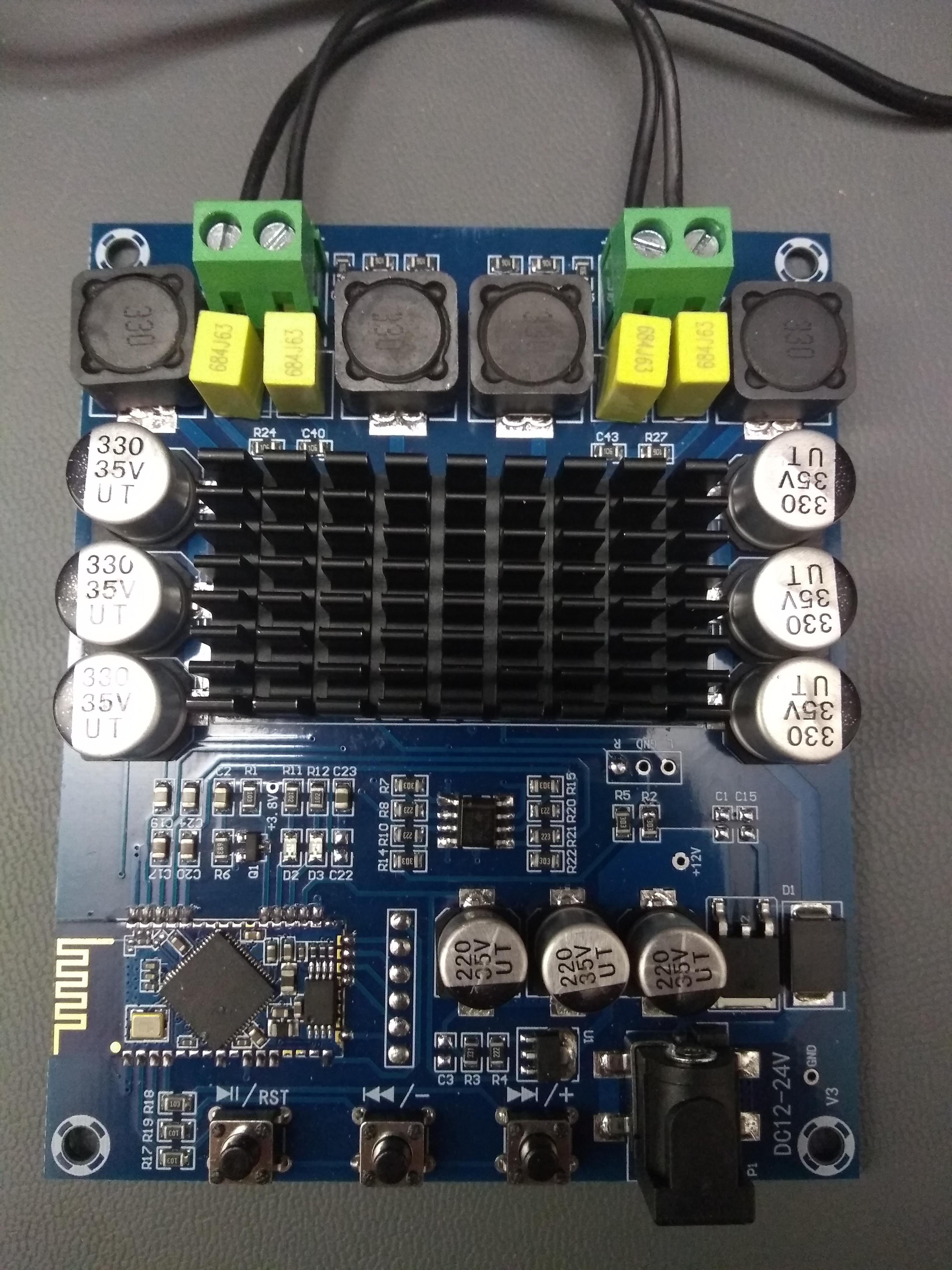
- Amplifier section
- Bluetooth section
- Noise
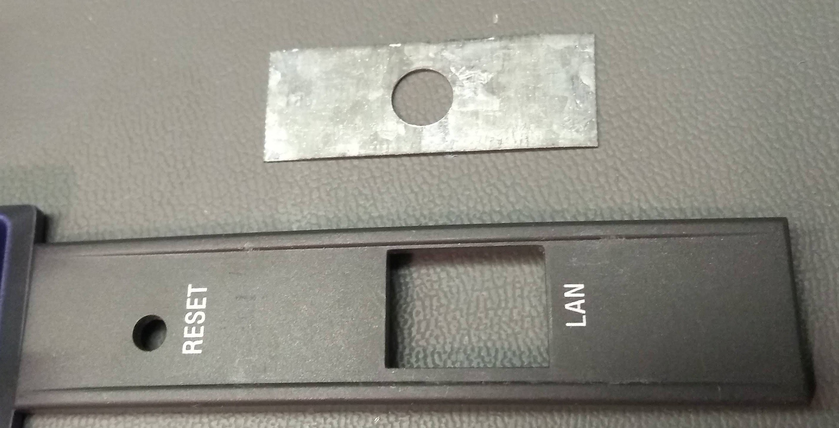
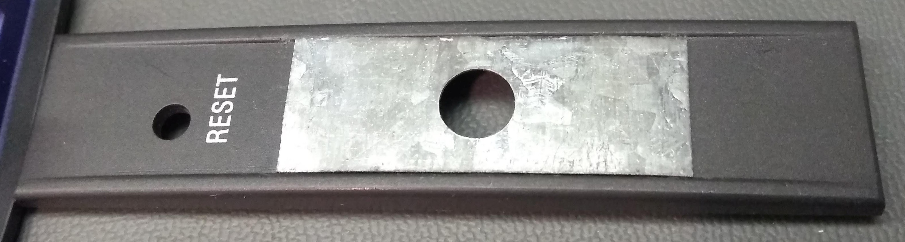
- Reverse engineering/Adding a hard volume knob
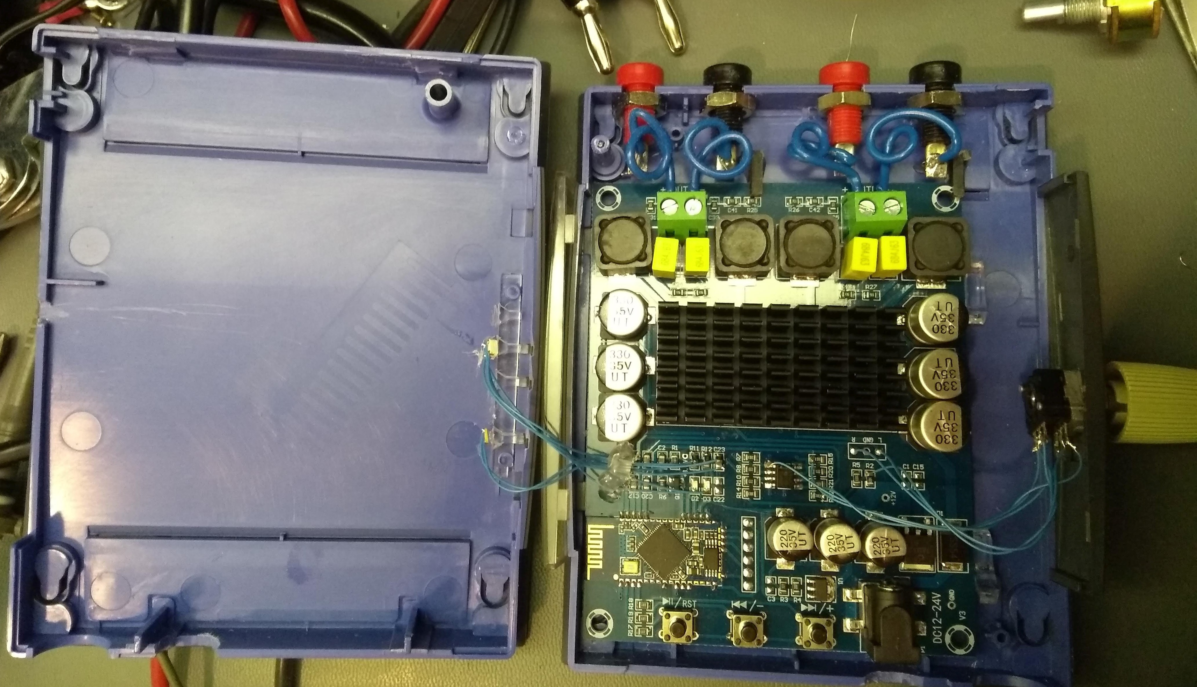
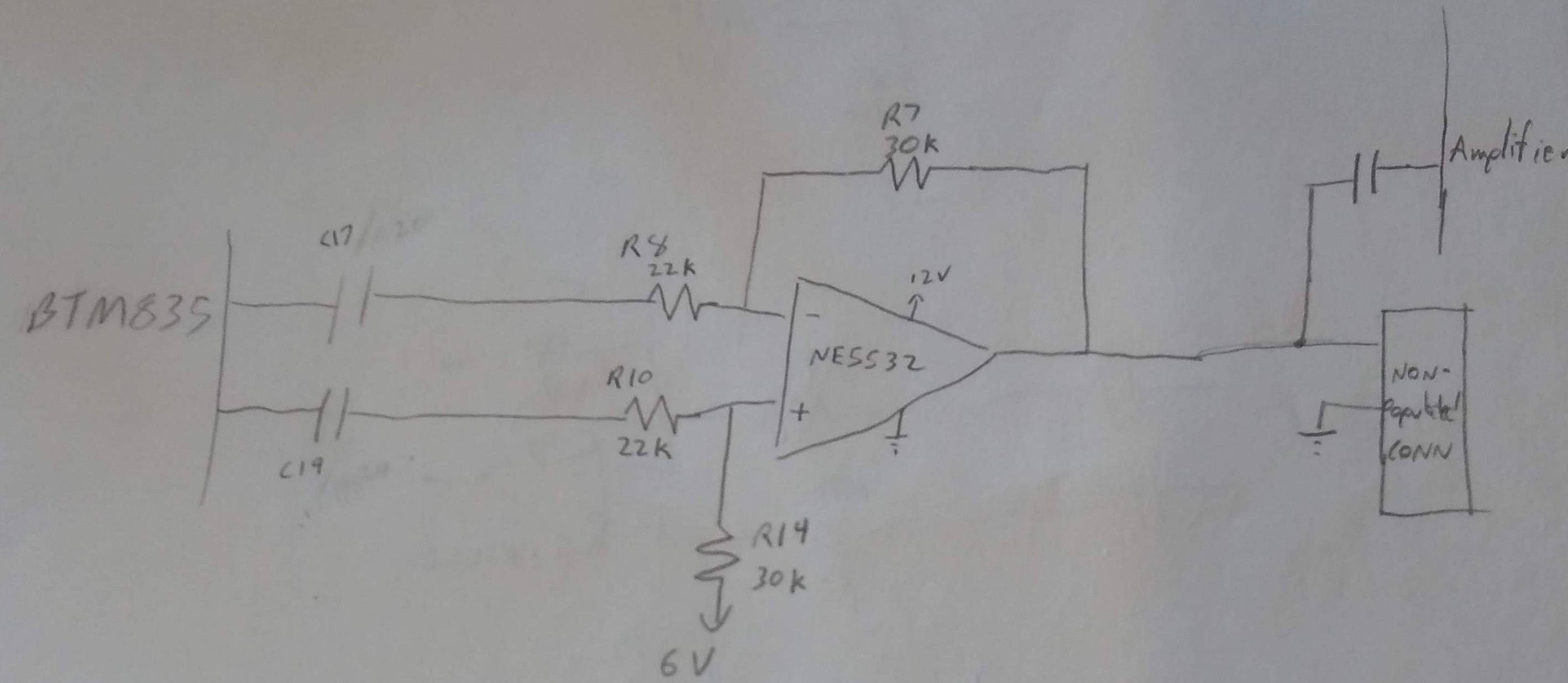
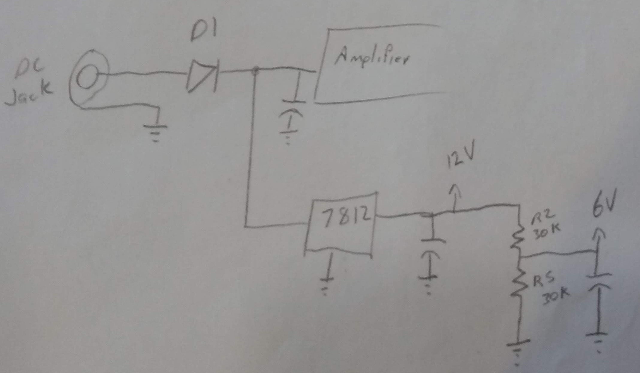
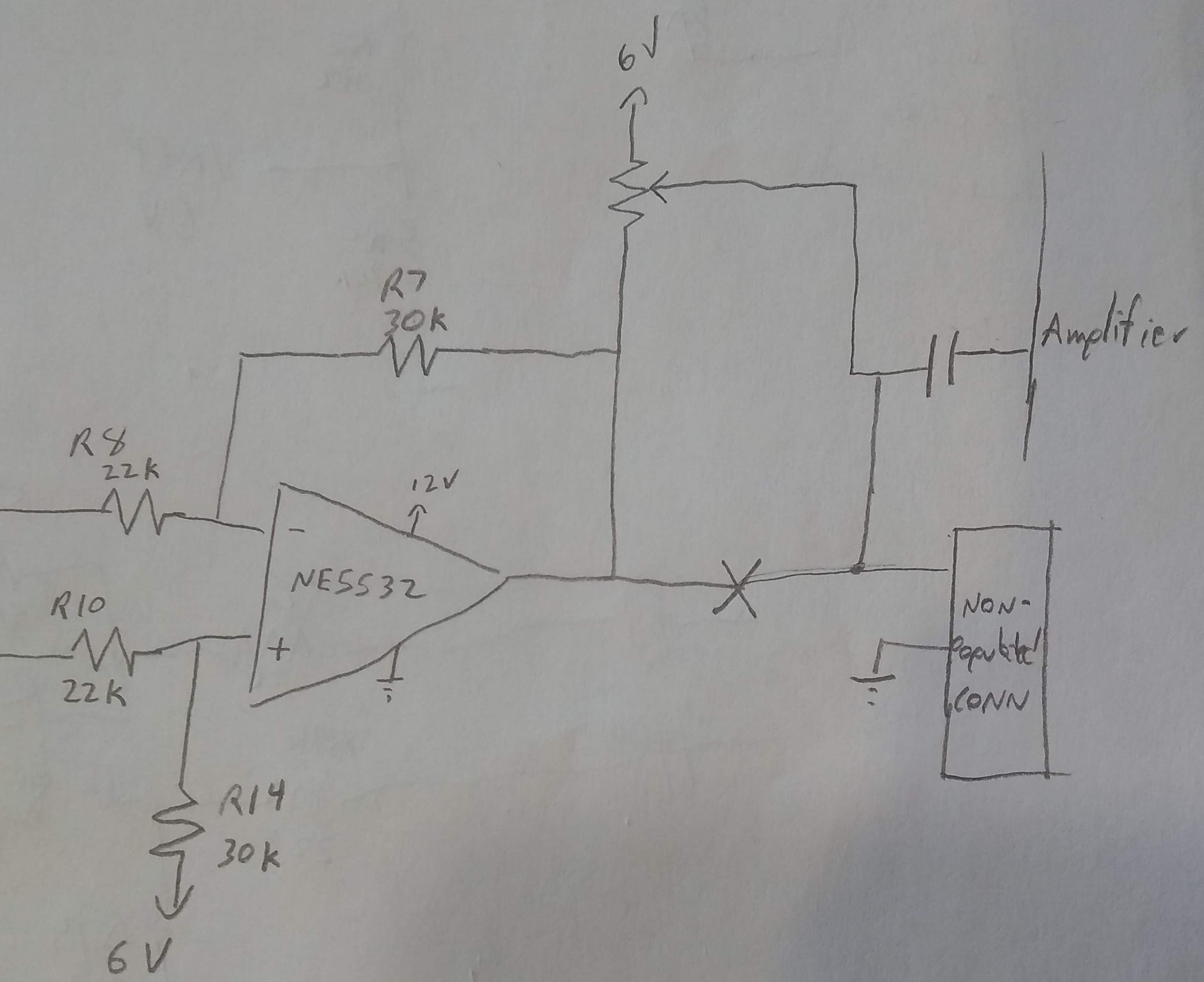
- Schematics
- Audio Path
- Power
- Input Power
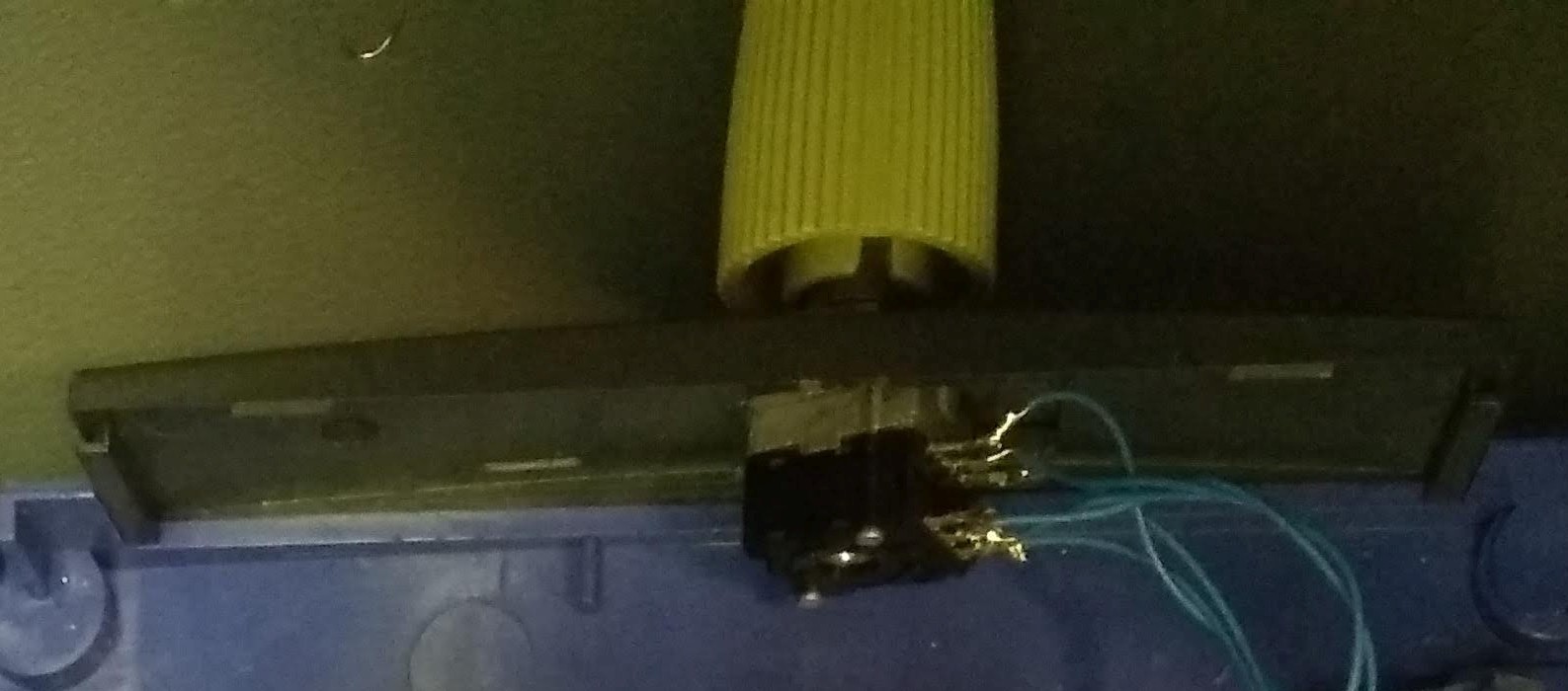
- Volume control
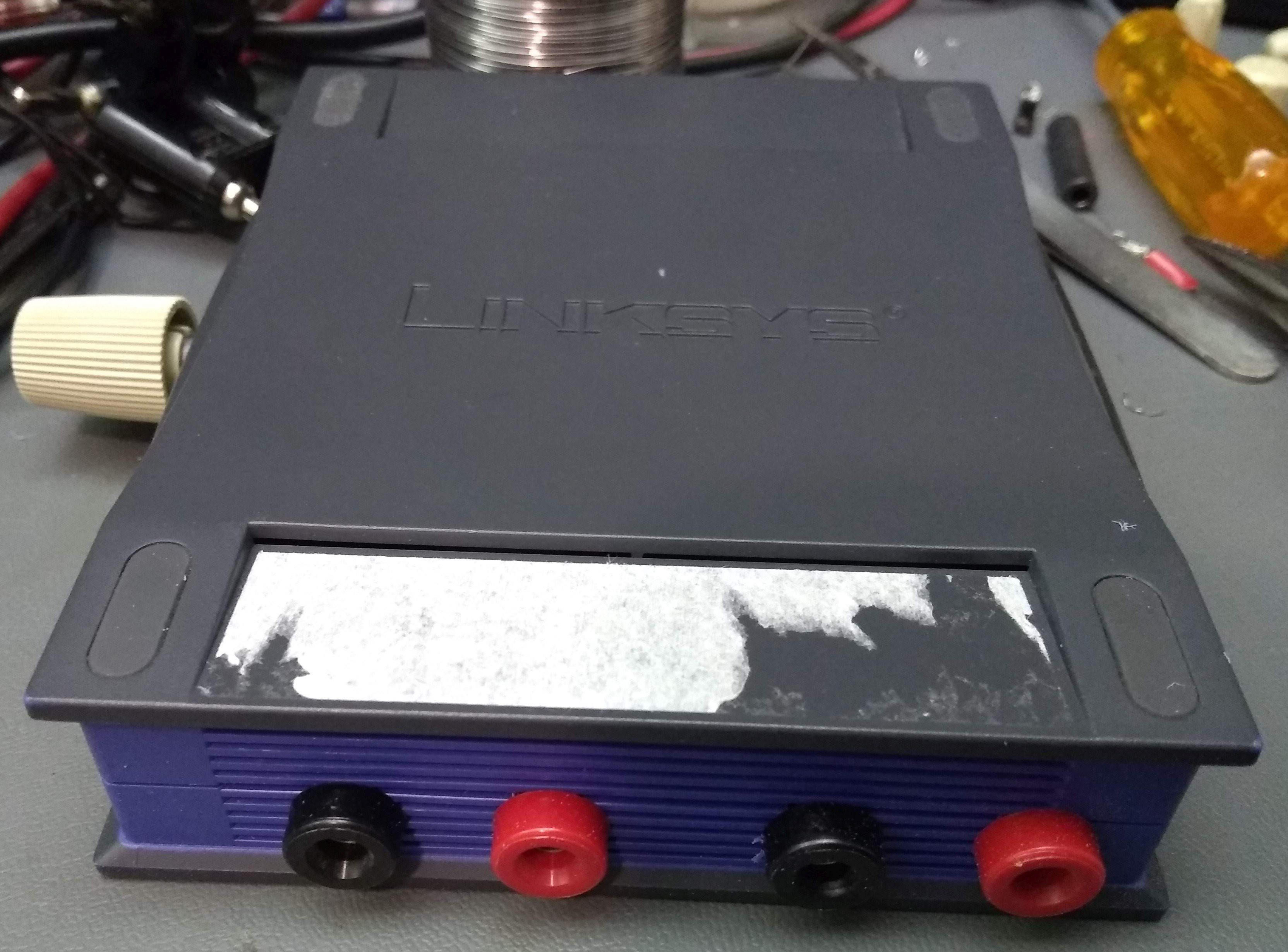
- Case
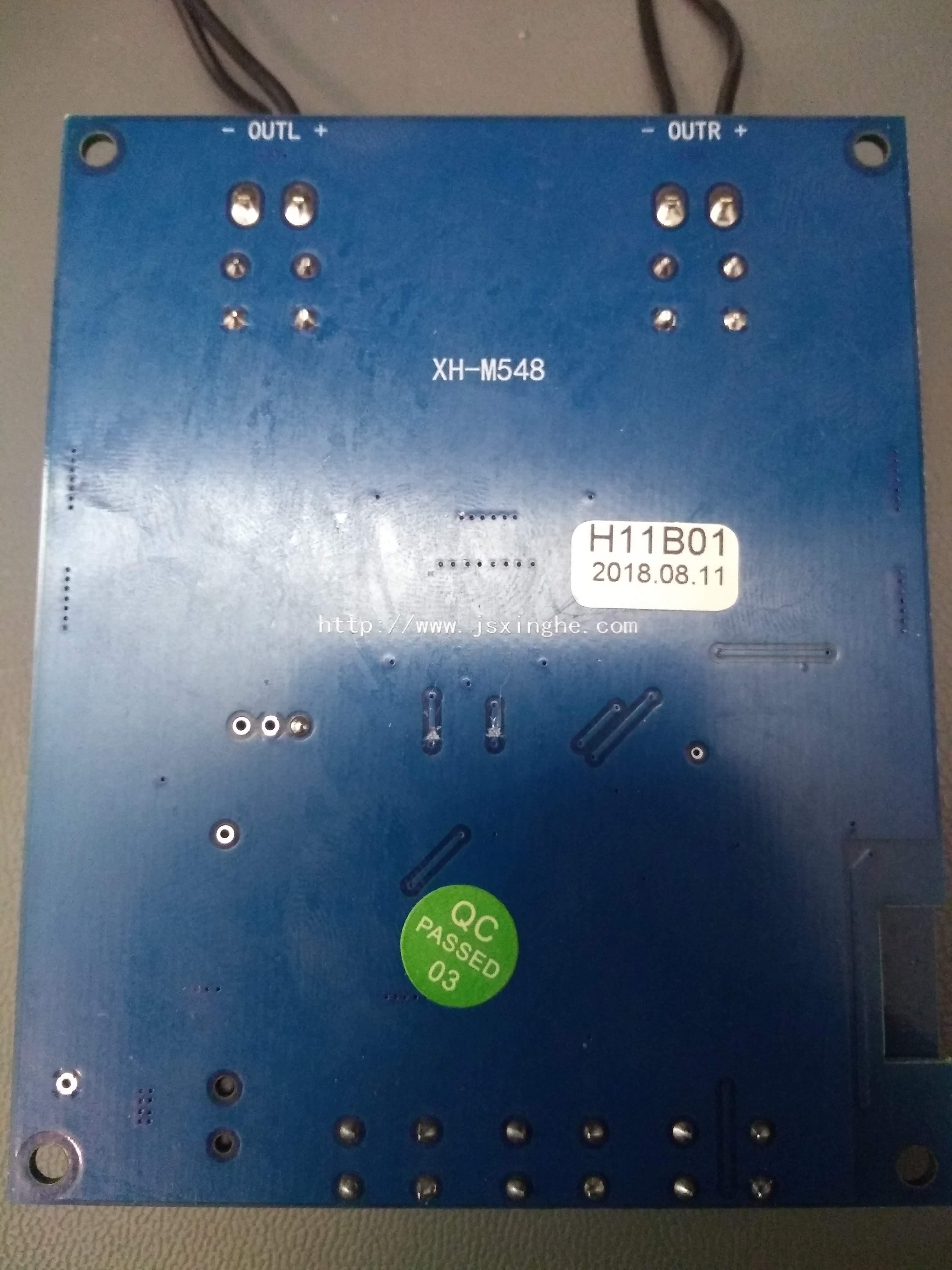
- Outputs
- Volume
- Board mounting
- LEDs
- Finished
- Final
- Future changes
- Portable speaker
 Arno
Arno
 Davide Ercolano
 Justin Scott
 John Wetzel