 Dilshan Jayakody
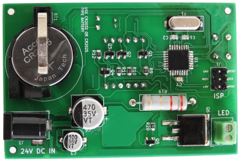
The core component of this programmable light is ATmega8 low power CMOS microcontroller. The main reason to select this microcontroller is it’s lower cost and higher availability. Except for the above two reasons this microcontroller also bundled with a rich set of peripherals which including 23 GPIOs, 3 independent timers, Two-wire serial interface, EEPROM, etc.
Apart from ATmega8 microcontroller, this system uses DS1307 real time clock to maintain system time. Like ATmega8, DS1307 is also a very popular RTC in the market.
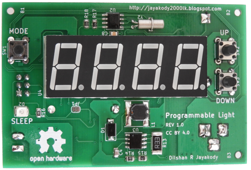
This controller is designed to work with a 24V DC power supply. The main reason to select 24V is that most of the medium power LED modules in the market are designed to work with that voltage. During my search all the medium power LED modules which I found are designed to work with 20V - 28V range. Out of those LED modules, the majority of modules are rated for 24V input.
For this circuit, the recommended power supply is 24V 1.5 A portable switch mode power supply. Except for the LED driver stage the all other parts of this light controller is designed to work with 5V. MC34063 DC-to-DC converter is used to supply 5V to those components.
To reduce the size I design this system using surface-mounted components, but this system can also build using through-hole type components. At the prototype stages, I build this system entirely on a breadboard using through-hole type parts.
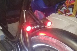
To build 7W light, I used LED lamp parts available in the market which including Warm white 7W LED panel, aluminum lamp shell (heatsink) and diffusing cap (lamp cover).


 cheperboy
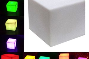
 Toby Jackson
 Christoph Tack
 Niel Malan
So I think adding a GPS clock would be easier instead of adding WWVB (the antenna for the WWVB is massive compared to this board). Has been on the back of my mind and then I saw KK99's work on the hackaday blog. Only issue would be clock updating indoors.
https://hackaday.io/project/164955-self-adjusting-clock-with-e-display
Looks like it is doable. Upgrading to a DS3231 for better accuracy would be nice too.