 Alan Green
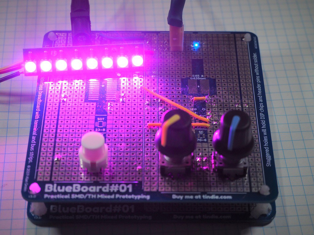
This project uses BlueBoard#01, and other components I had in cupboard. I'm pretty pleased with the result - it works, it's useful and it's acceptably tidy.
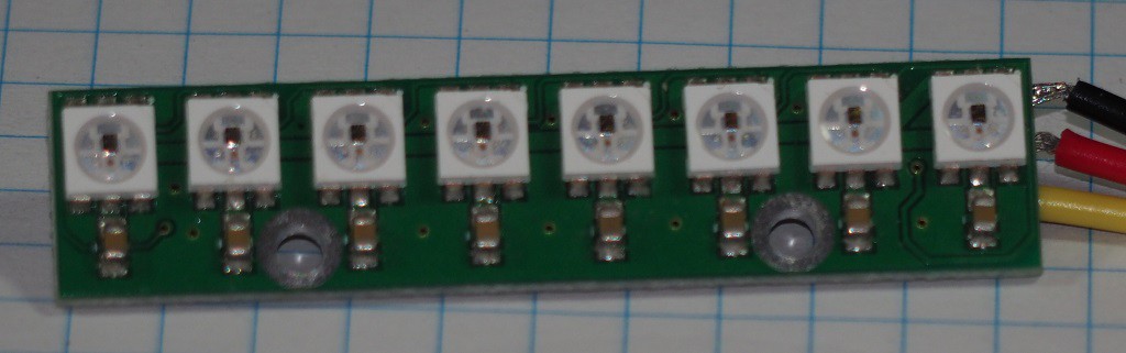
This was the final prototype of BlueBoard#01 before it went into production. The differences are:
- It uses HASL (solder) instead of ENIG (gold) plating.
- The placement and size of the mounting holes changed.
This project serves as an example of how to use BlueBoard#01 for one off projects.


 Matthias Kampa
 Crypto [Neo]
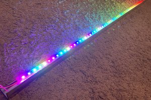
 Jon Kunkee
 mulcmu