 Leo Vu
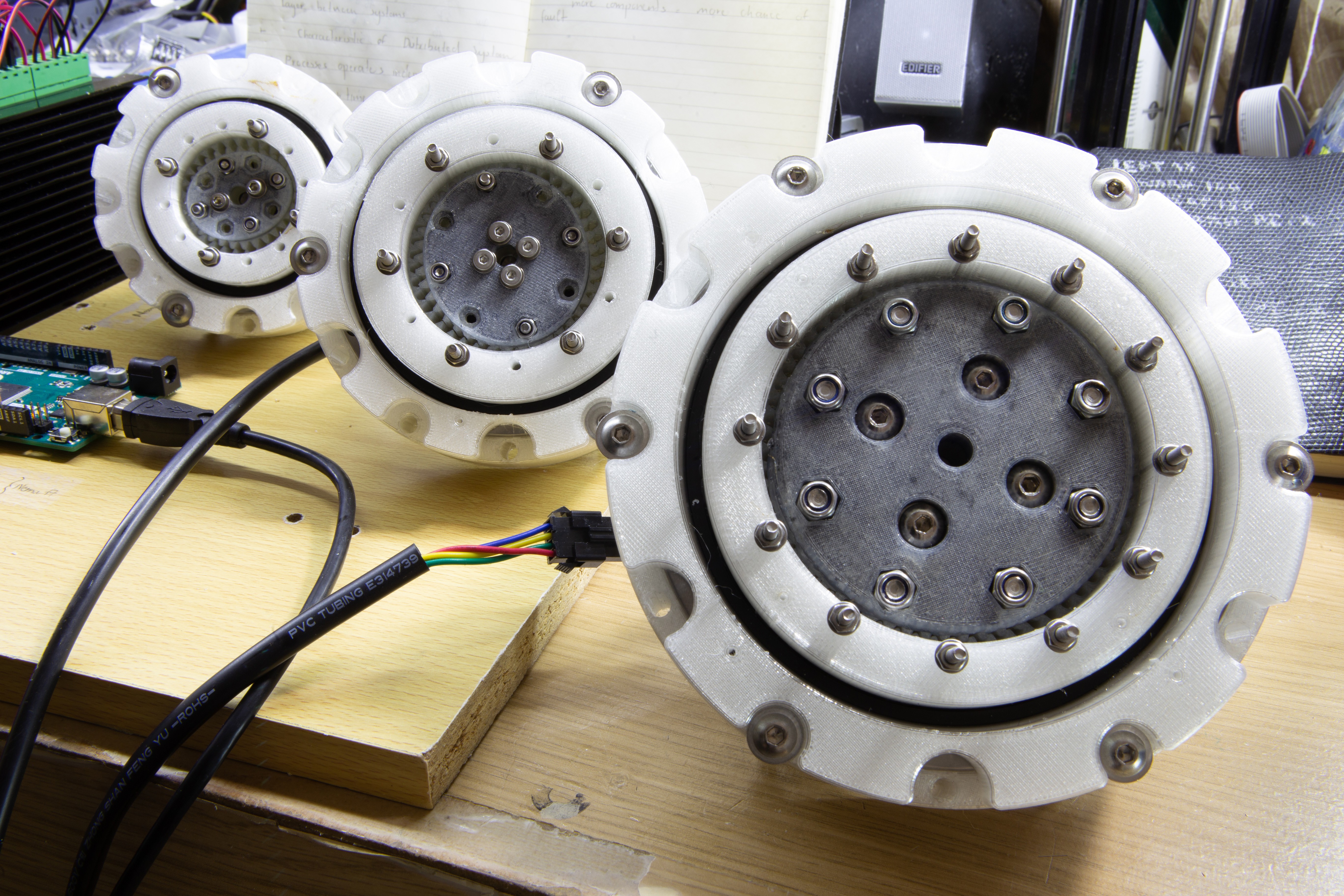
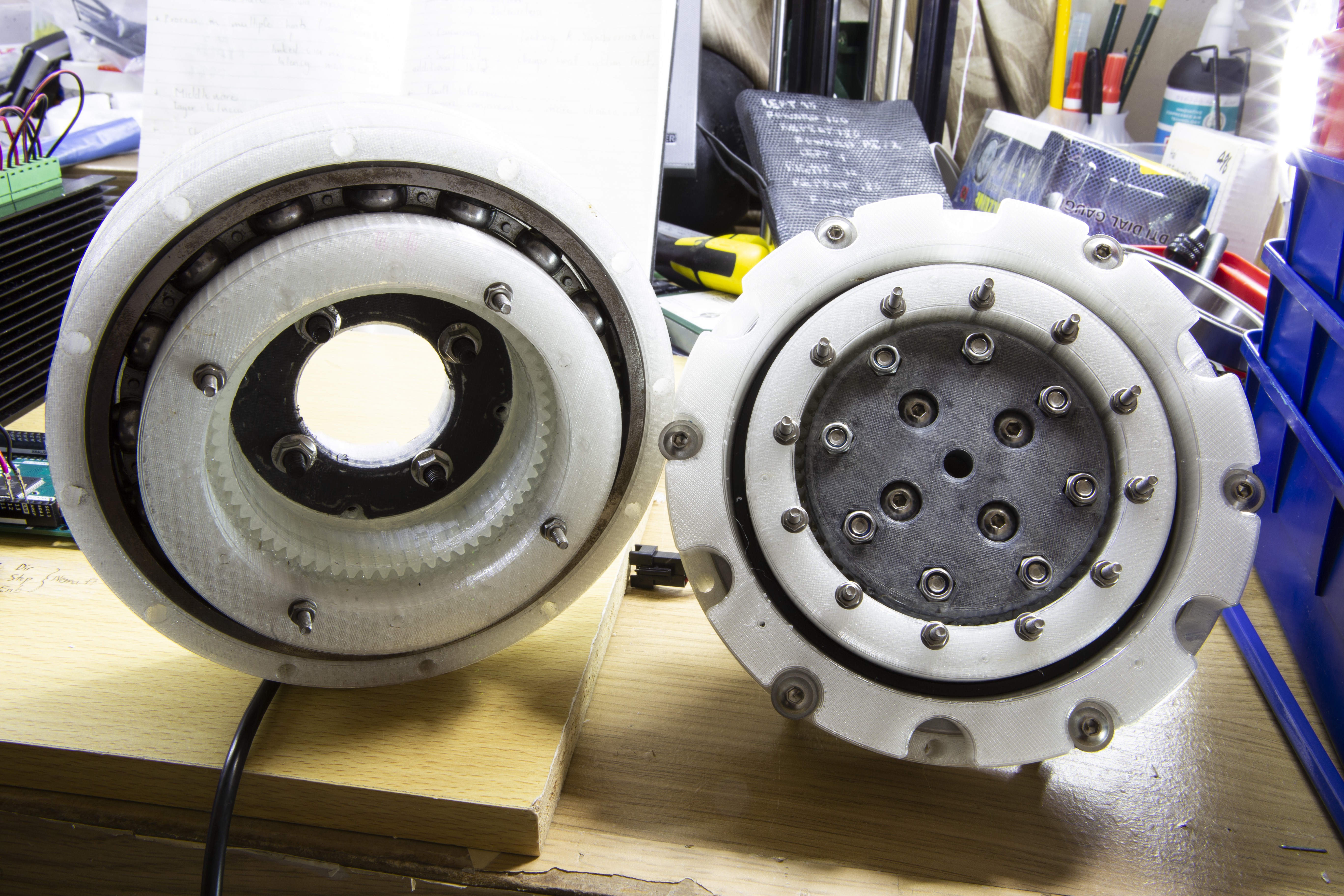
Final set test (1:15, 1:21 and 1:31 ratio).
Specs:
- Strain wave gear, ratio 1:31, 1:21 and 1:15
- Weight (no motor): 1241.1 g (1:31)
- Overall diameter: 145 mm
- Cooling: passive
- Backlash: < 5 arcmin
A compact modular design of the strain wave gear for general robotic applications.
Already have an account? Log in.
To make the experience fit your profile, pick a username and tell us what interests you.
Final set test (1:15, 1:21 and 1:31 ratio).
Specs:
Sorry for the incomplete upload.
6 axis robot project: https://hackaday.io/project/165680-3d-printable-6-axis-robot-dauphine
Uploaded the assembly .step file for application integration.
Version 1.0 used a Deep Grove Ball Bearing instead of a Cross Roller Bearing. I just want to see how good the gear teeth meshed with each other.
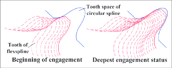
This is the tooth template I used. It's a double arc profile for additional rigidity of the flex spline.
*Source: https://www.harmonicdrive.net/technology/harmonicdrive
And the meshing analysis:
Thanks for posting this design!!!! I would love to see some torque numbers on the prototypes you made. I did a quick prototype in PETG and it seems to work pretty well. I shrunk it to fit a 70mm ID bearing and ran out of room inside the wave generator so I made an elliptical bearing which turned out pretty good. Here is a link to my thoughts on doing a printed elliptical bearing. https://youtu.be/2rg56Bp5kjA
I did some torque testing today on a PETG 77% scale version. I was able to move around 900 grams at the full RPM of my drill input and stop immediately with no failure. Ratcheting occurred at around 8Nm. It is notable that the full assembly was not completed and the outer ring was riding loosely on the bearing with about 1mm of potential axial play. The wave generator was also not firmly fixed in position and I noticed ratcheting would occur if it crept out. The best torque was observed when it was seated fully inside the flexspline. I'm interested in what results others have seen?

I really like this design. I am working (probably foolishly) on integrating a 3D printed bearing into this design to avoid the cost of the crossed roller bearing. Photo here. I have just completed the build and waiting for controller to arrive to test the motor.
https://drive.google.com/open?id=1ycgIQaFZAFqVjEharbUmqq09vW8Fon5X

Hello.
Can you tell me what material of FlexSpline?
I don't know what is it ? PETG, TPU or Nilon ?
Best 3D printed strain wave reducer seen so far! I wonder is it back drivable? Also I am waiting for your experiment results on maximum torque.

Hello!
We are in the US and ordering the ‘big bearing’ (*** See below!). Has anyone located a US supplier or perhaps a MasterCarr link we could purchase this from? Or maybe a cheap alternative for quick prototyping? Lowest we found is about $150. Thanks so much!
RB9016UUCC0 P5 Crossed Roller Bearings (90x130x16mm) Machine Tool Bearing TLANMP type High rigidity Medical Device Bearing***

I do not have one that is shareable, apologise for the late reply.
Very well done, the most serious attempt I've seen so far with a 3d print of one of these. What kind of tooth profile did you use for the circular and flex gear: normal involute?
Yes, I linked some papers and materials that I used for tooth involute in the project log section.

I'm trying to build the mid sized version, 1-21. I wonder what bearings you used for the ellipse drive? 3x6? 3x8?
It looks like the ellipse drive is far too big. It fits perfectly in my gears without the bearings, just using on the heads of the M3 hex bolts. At least I can see the strain wave moving, it looks like your teeth profiles fits really well and is smooth running.
I printed the spur gear in PP to get a very smooth ride. It might be bad for the backlash since it is quite flexible. We will see once the ellipse gets sorted.
Forgot to mention that, I used 683ZZ 3X7X3 for both of the smaller one. Do note that I only used 4 of them not 8, because the teeth are quite large and the curvature of the smaller one doesnt really allow smaller motors to output enough torque for the rotation. In additional, even two bearings are viable as the smaller gears dont tend to vibrate as much as the bigger one.
Now come to the size of the wave generator. Once you have the bearing in, the bolts are squeezed inwards for the bearings to fits the inner curve, that is the pretensioning for zero backlash. However, I believe that most of the printers out there suffer dimension problems. This is due to the nature of FDM 3D printer, link here: https://www.3dhubs.com/talk/t/printed-dimension-differ-from-original-model/5440, and your part maybe too much oversized, maybe due to the material used, I dont know. I printed my part on the Markforged Mark 2, which itself has compensation. Not to say that it is 100% accurate, but it worked for me.
What you can do is try to scale down the part, either uniformly or just the longer axis. Then drill the holes for the bolts. Don't use an oversized drill bit because if you look carefully you will see that I designed a built-in spacer for the bearing to rotate smoothly even if you over tighten the bolts. I will also try to print one on my custom printer to check, I guess it should also be bigger than the part printed on the Markforged. I will see what scale I need to set for it to fit.
Thanks for the reply. Measuring the CAD model I can see that the ellipse drive is 1mm oversized. Measuring my printed model it looks about 2mm oversized. The extra mm is probably from the extra ~0.2 you get from each printed surface connecting to another printed surface. Scaling or some CAD work will get it sorted.
My printers produce very exact measurements, size difference are mostly down to the surfaces not being totally even.
I'm reworking the model to be smaller. Same gears but smaller outside. I want to use it on a parallel Scara arm I'm working on and I do not need that beefy (and expensive) cross roller bearing.
Sure, feel free to modify the parts as you need as long as it is not for commercial products.

Nice work! How did you measure backlash? Is there any way to decrease it?
I'm also interested in max torque. This may be useful for telescope mounts... Cheers! Tyler
The output flange of the gearbox was mounted to a 100 mm VSlot and then calibrated to touch the dial indicator at 50 mm mark on the bar and 0 mark on the indicator. Then the motor was set to move 2 step at full step mode many times. The dial indicator ranged between 2.05 - 9.2 indicating the max backlash of (2 * 1.8 / 31 * 50 - 2.05) / 50 = 0.0752 deg, around 4.51 arcmin. So to be safe I just say that the maximum backlash is around 5 arcmin.
With my stepper motor the gearbox has already provided quite a good resolution, as you can see there I had to use a very short vslot distance to make the measurement in range with the dial indicator. Provided that I have had a better resolution motor, I would still not benefit much since if I make the size of the wave generator tighter to reduce backlash, teeth deformation would certainly cause extra play (not backlash, but mechanical deformation).
That's a clever method of measuring backlash. Good point about the added play, it would also probably require more torque from the motor. Thanks!
Awesome job that looks one of the most robust 3D printed strain wave gear I've seen so far. I will definitely consider your design in the arm I'm building
Could you please upload the step file of the 1:15 and 1:21 too ?
Yes sorry I thought I uploaded them, somehow the file management systems messed up the files with the same name. I uploaded the stl as well as the step files for the 1:15 and 1:21.
Remember that you need a very precise printer to print the circular spline, the flex spline and the ellipse drive (wave generator). I used my Markforged Mark 2, if say your ellipse drive wont fit you need to scale down some part while scale up some other part, best to go slightly with finer details.
Thanx man I guess I will try to play with the printer settings a little bit and calibrate it to get good results . Good luck with your robotic arm it looks awesome !

Have you tested for backlash or hysteresis? I imagine these could put to a decent amount of torque -- though I'm curious as to how rigidity compares to something like similar-cost planetary gears once you account for flexing in the 3d printed components. Very cool and will follow along
Yes I dis use a dial indicator for backlash measurement, although not officially. The reason was that I will eventually replace the Nema 23 motor with a bigger closed loop hybrid motor that is capable of outputting far better resolution, hence the better precision for backlash measurement. At the moment the max backlash is as suggested 5 arcmin, can be smaller I dont know because that is the maximum reliable resolution I get with the motor.
About the rigidity, I have been messing with these type of 3D printed gearbox for around 2 years since I saw Simon Merrett's video about it on youtube (who I believe is also on Hackaday, https://hackaday.io/smerrett79). The thickness of the flex spline was adjusted many times to maximise the strength of both the ring and the teeth while keeping it fairly flexible for radial deformation. Each of the different ratios have different thickness for the flex spline ring. I am fairly confident that before the part broken by deformation it will have greatly deformed by the heat from the fiction, hence the large amount of silicone grease as in the assembly timelapse video. I once run the 1:31 ratio gearbox continuously around 52 hours and I believe the whole thing is just slightly hotter than normal due to the heat dissipated from the motor itself, without anything break of course.
The strength of the teeth is another story. Deflection and backlash could certainly come from teeth deformation under high load, although I used module of 1.25 mm that is fairly large for a gearbox. As mentioned in the previous reply I will have to wait for the motors to come from China, then testing with the robot will be much easier.

Have you measured max torque? Very curious on that
No I have not. But I will definitely do that because I am using this gearbox for my 6 axis robot. I am waiting for the motor to come.

 Carl Strathearn
 Ric Real
 Josh Cole
 Josh Starnes
I enjoy your work. I am interested in creating a strain wave gear assembly. I am reviewing the 1:31 unit step file because I am using NEMA 23 motors. I found that the motor shaft does not connect to any part within the unit. Is this something you overlooked?