 Maave
MaaveWHY:
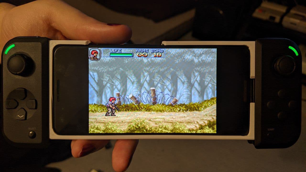
I want to play action/platformer games on my phone. The straw that broke the camel's back was "Prinny: Can I Really Be the Hero?" - I couldn't beat a boss because my fingers kept missing the intangible touchscreen controls. I want a gamepad that is compact to carry, comfortable to hold, and works with multiple phones.
HOW:
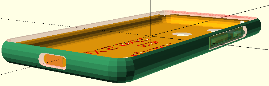
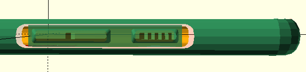
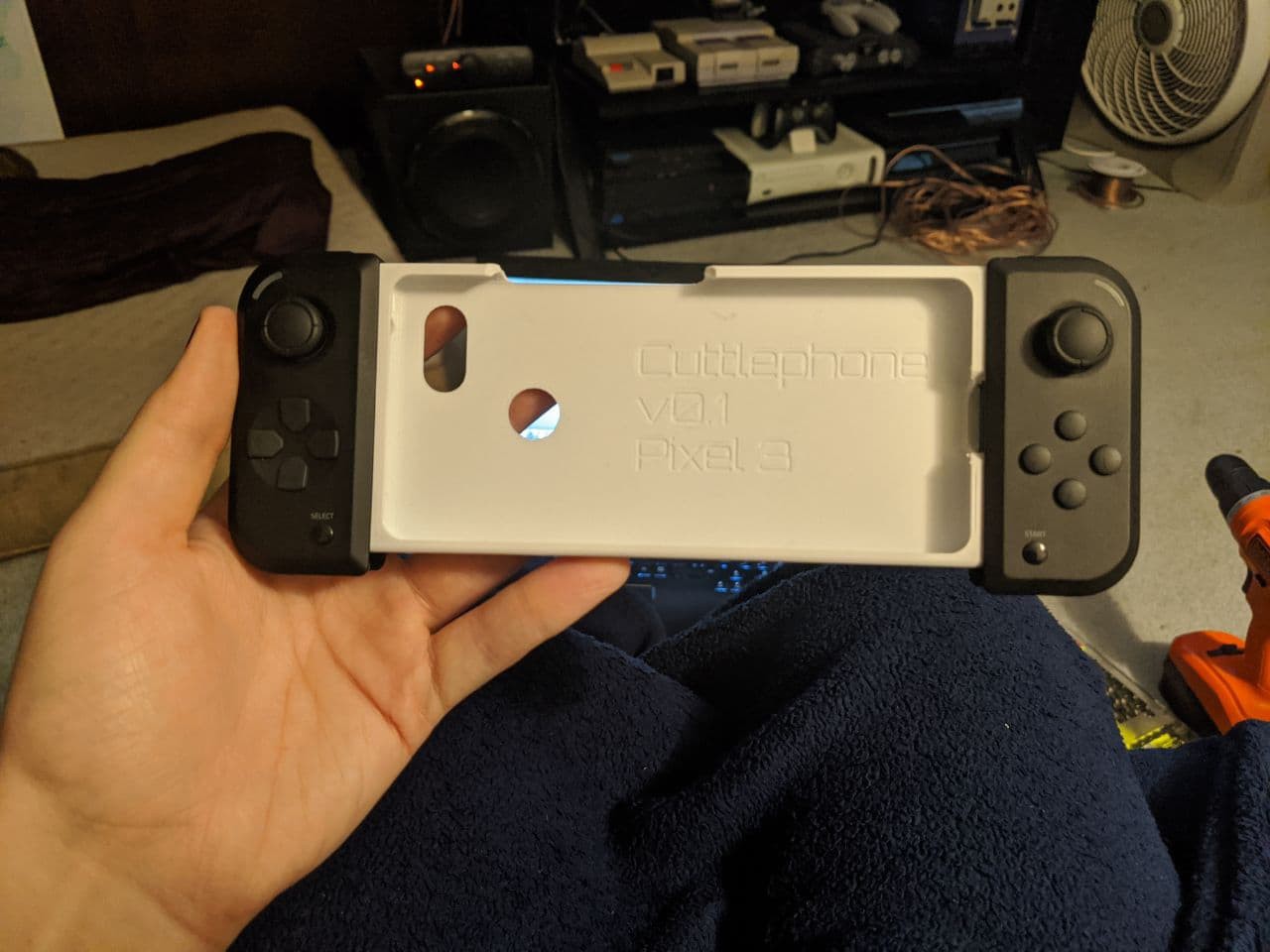
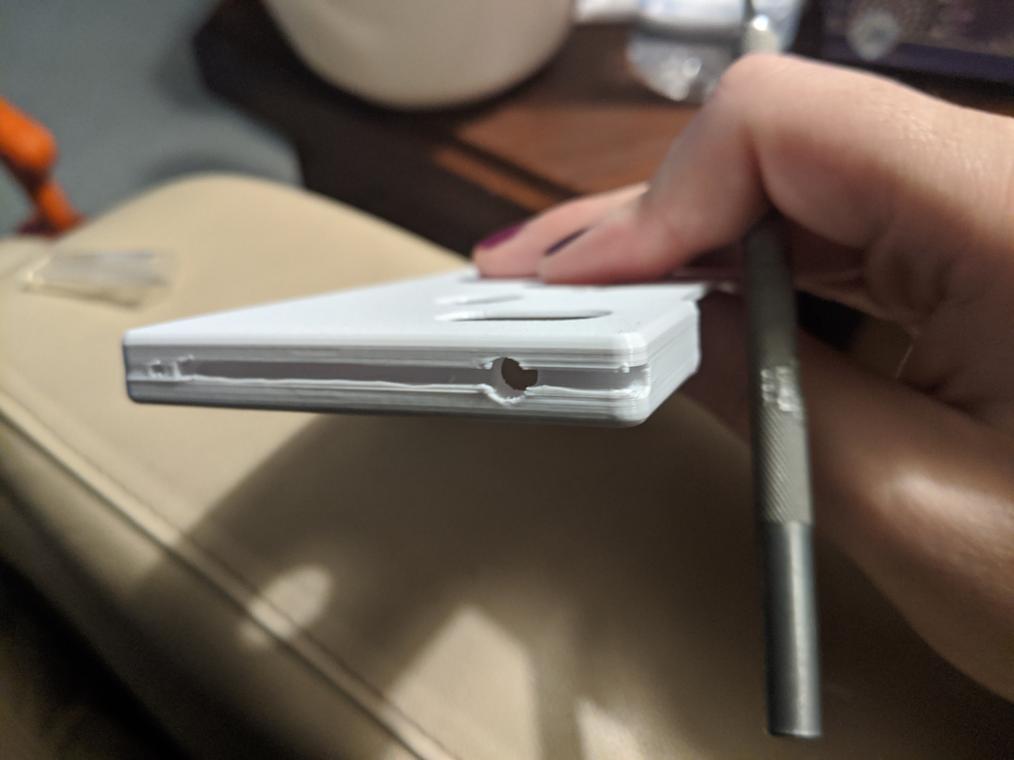
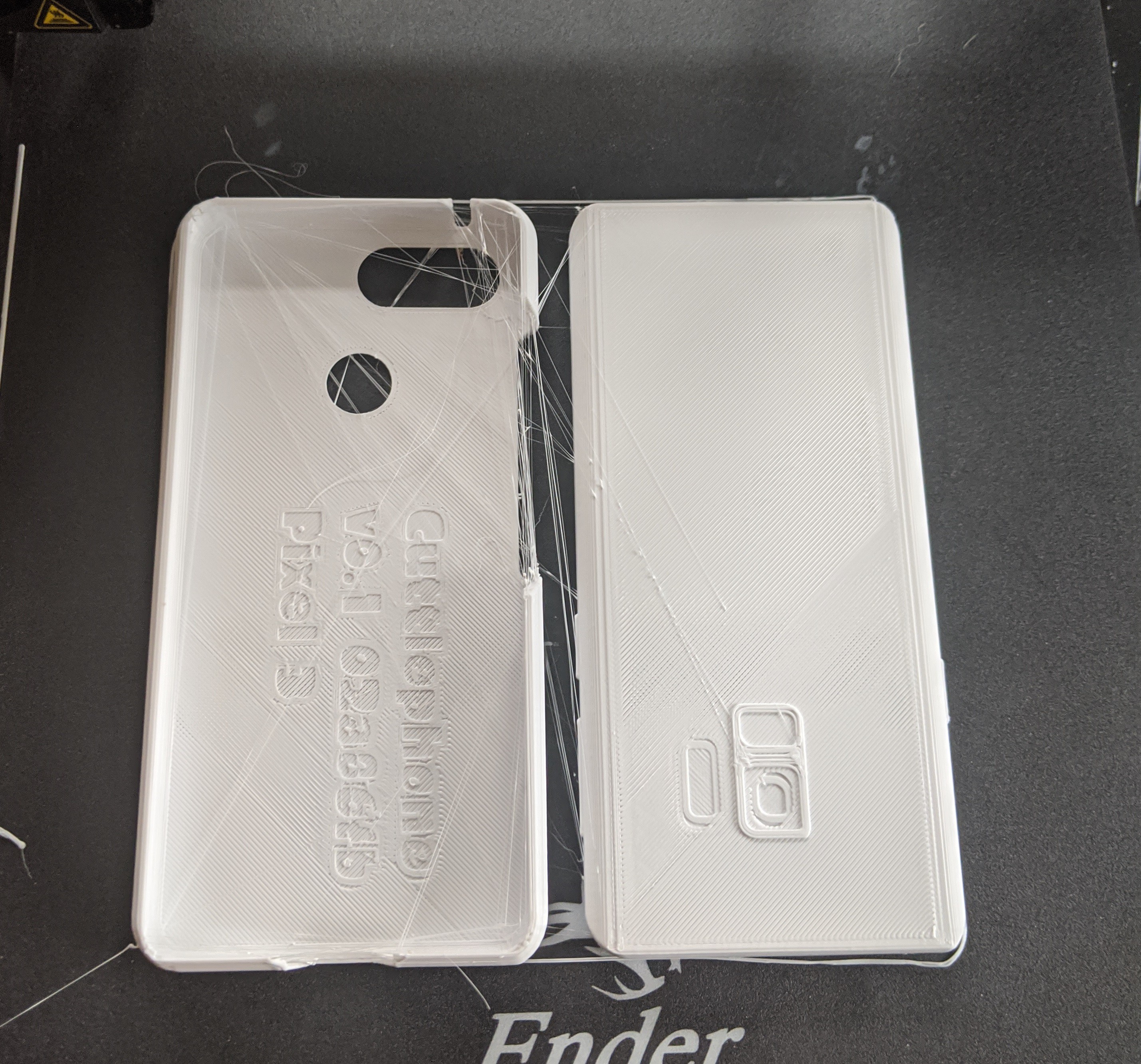
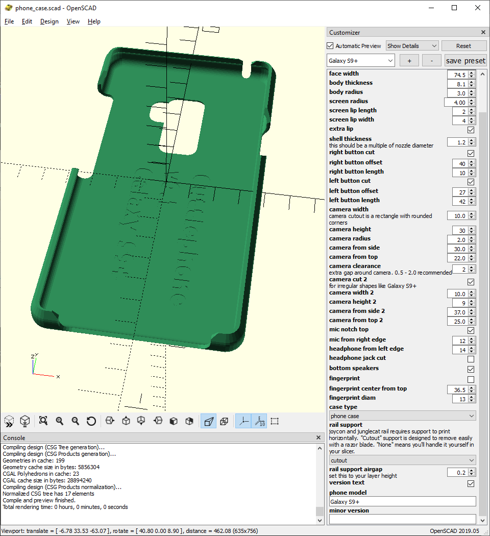
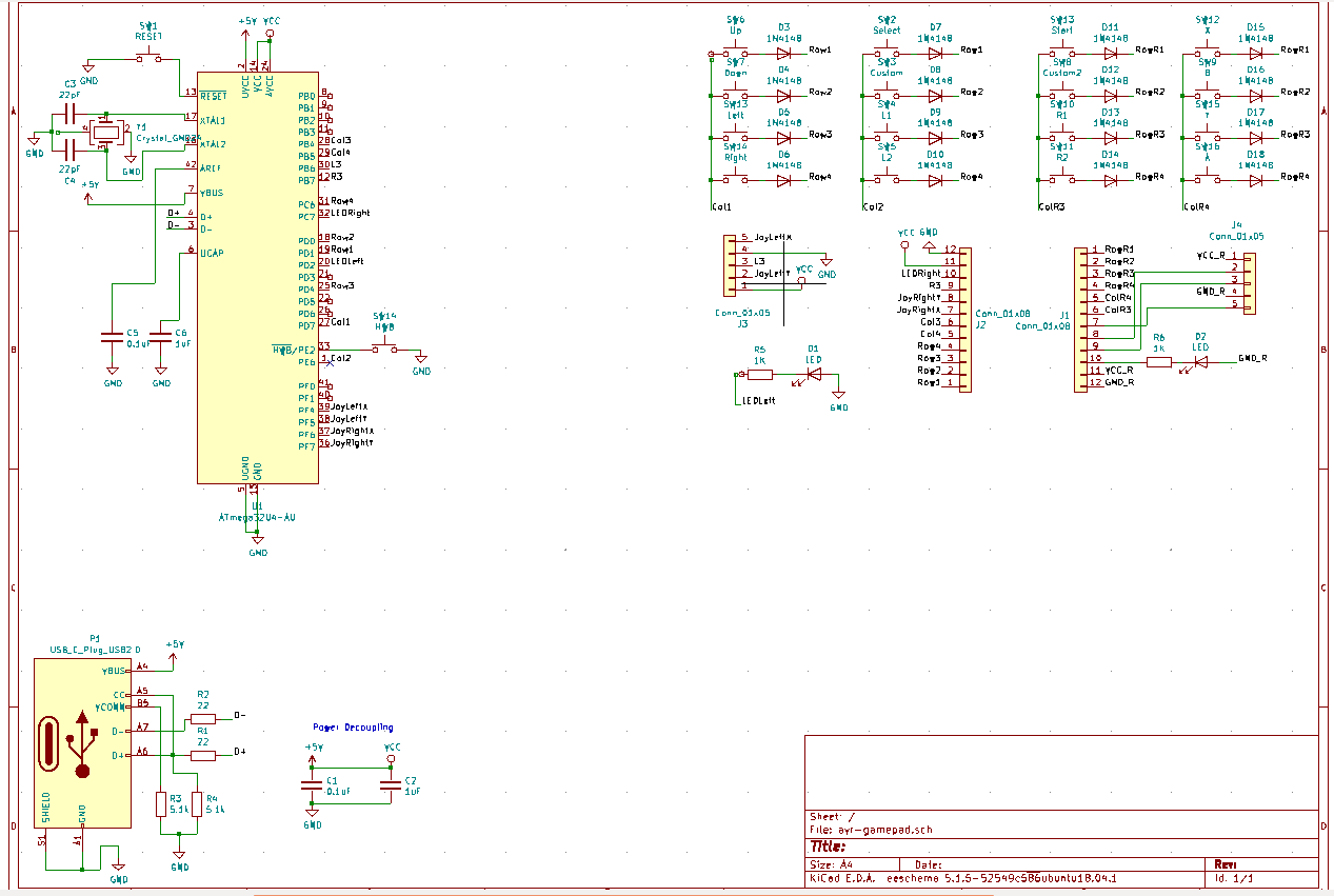
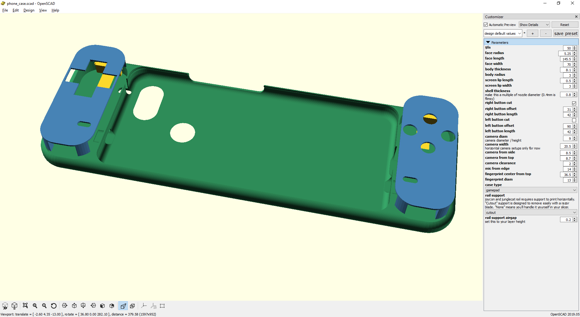
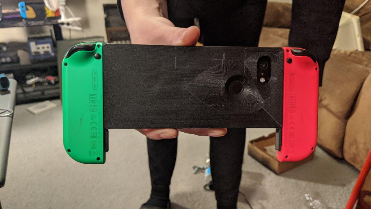
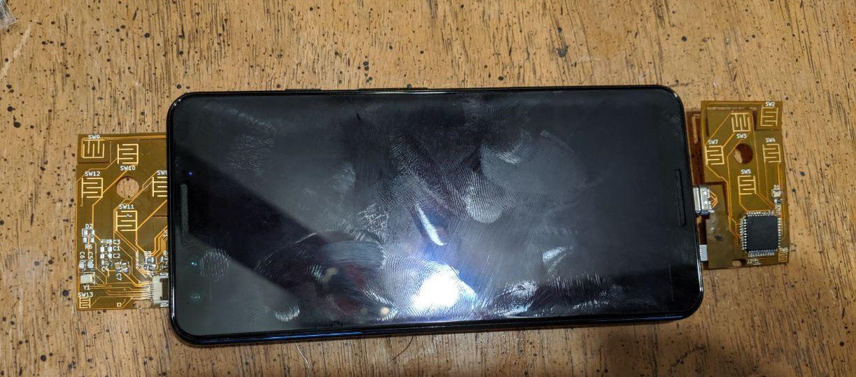
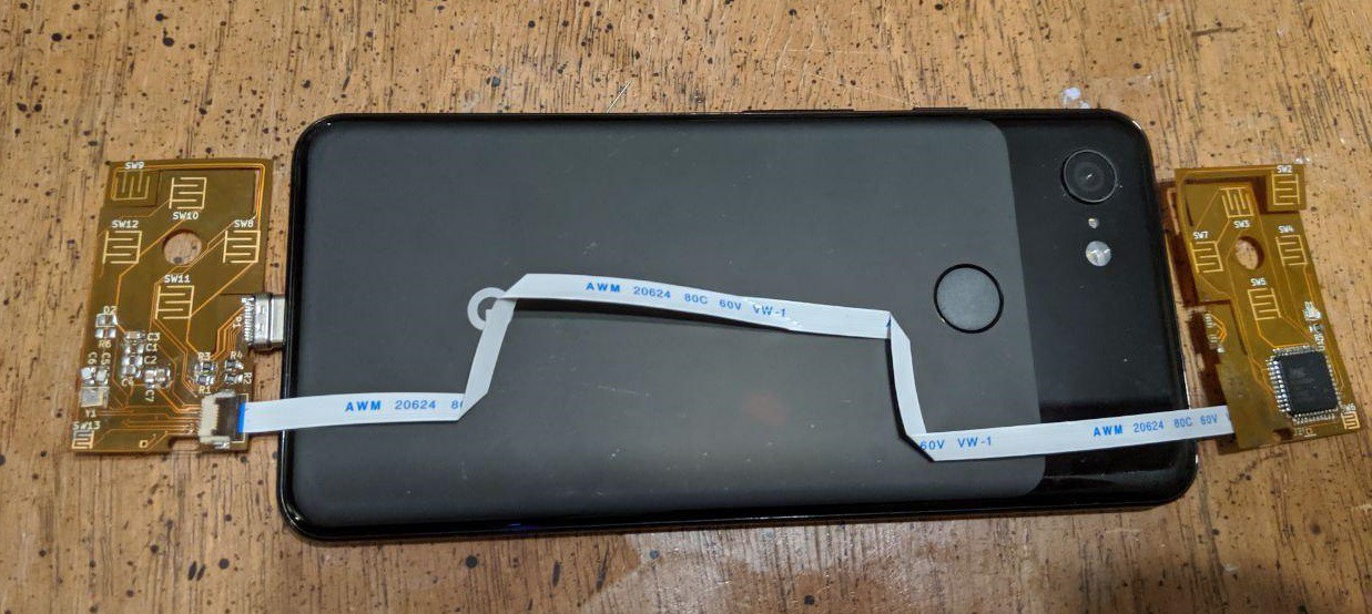
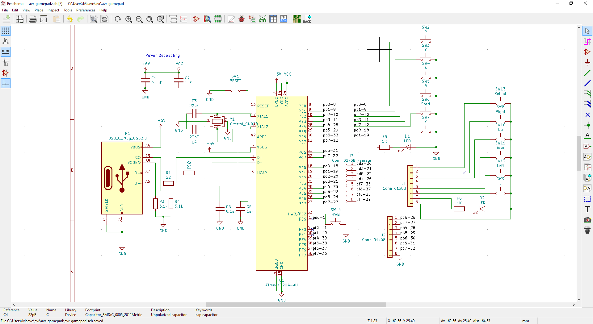
This version of the project uses USB-C to directly connect to the phone, and I plan on using an AVR chip to handle USB communication. Using a physical connection complicates phone compatibility but eliminates the battery and has better upgrade potential (battery bank for the phone, headphone jack, microSD slot, etc) through USB. The shell is 3d printed to adapt to multiple phones. Future versions can involve the community for improvements, support for more phones, and artwork.
INSPIRED BY (R.I.P.):
Xperia Play, OpenPandora., HTC Dream (G1), DS Lite, PSP

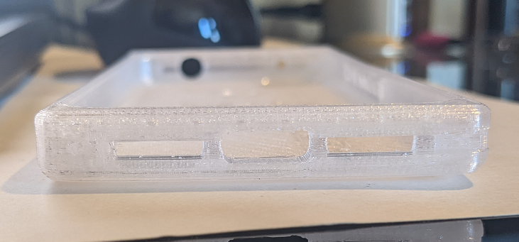
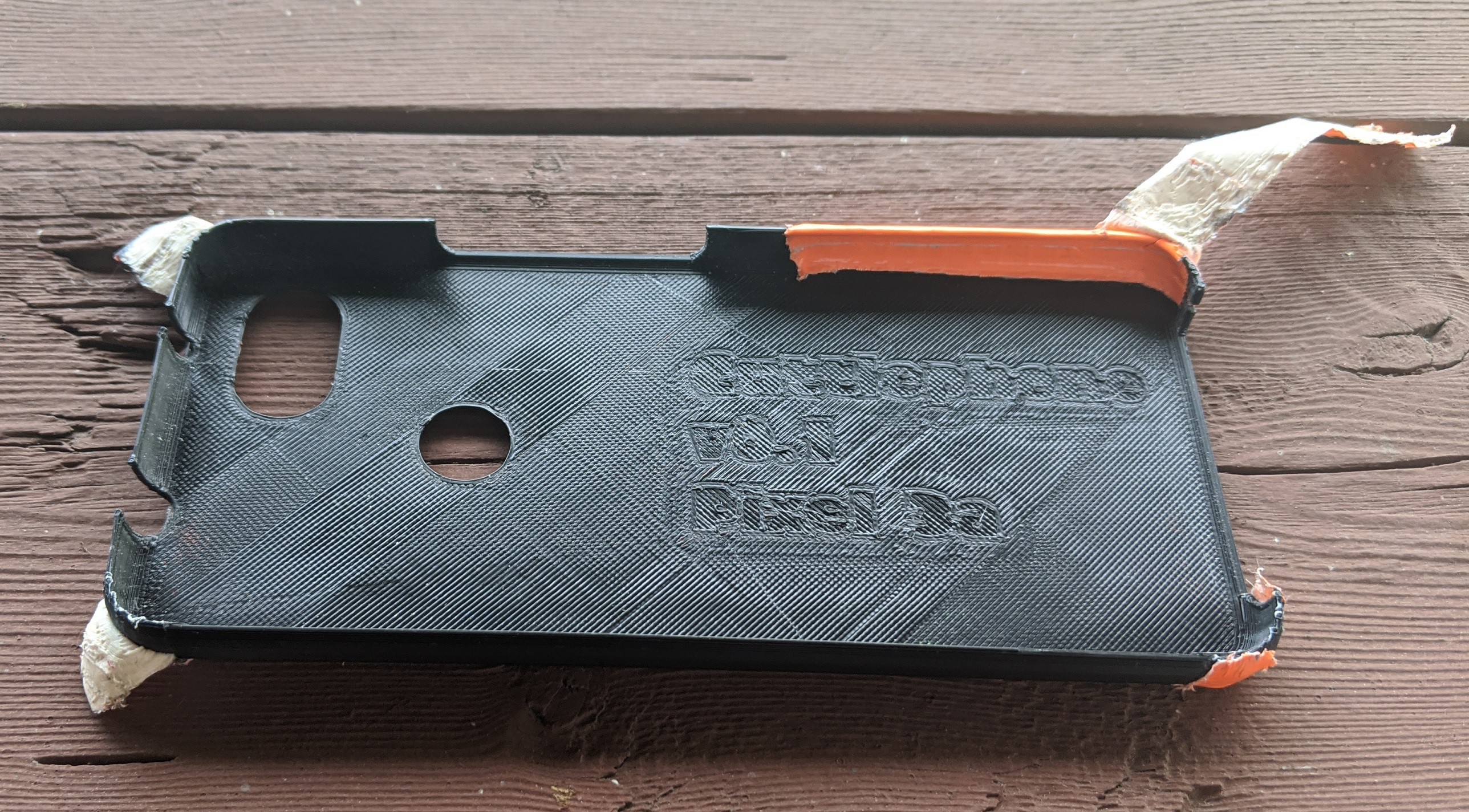 Here's my friend's case after a month of beating on it. He used duct tape to patch the corner and improve for visibility. We'll be trying different colors later.
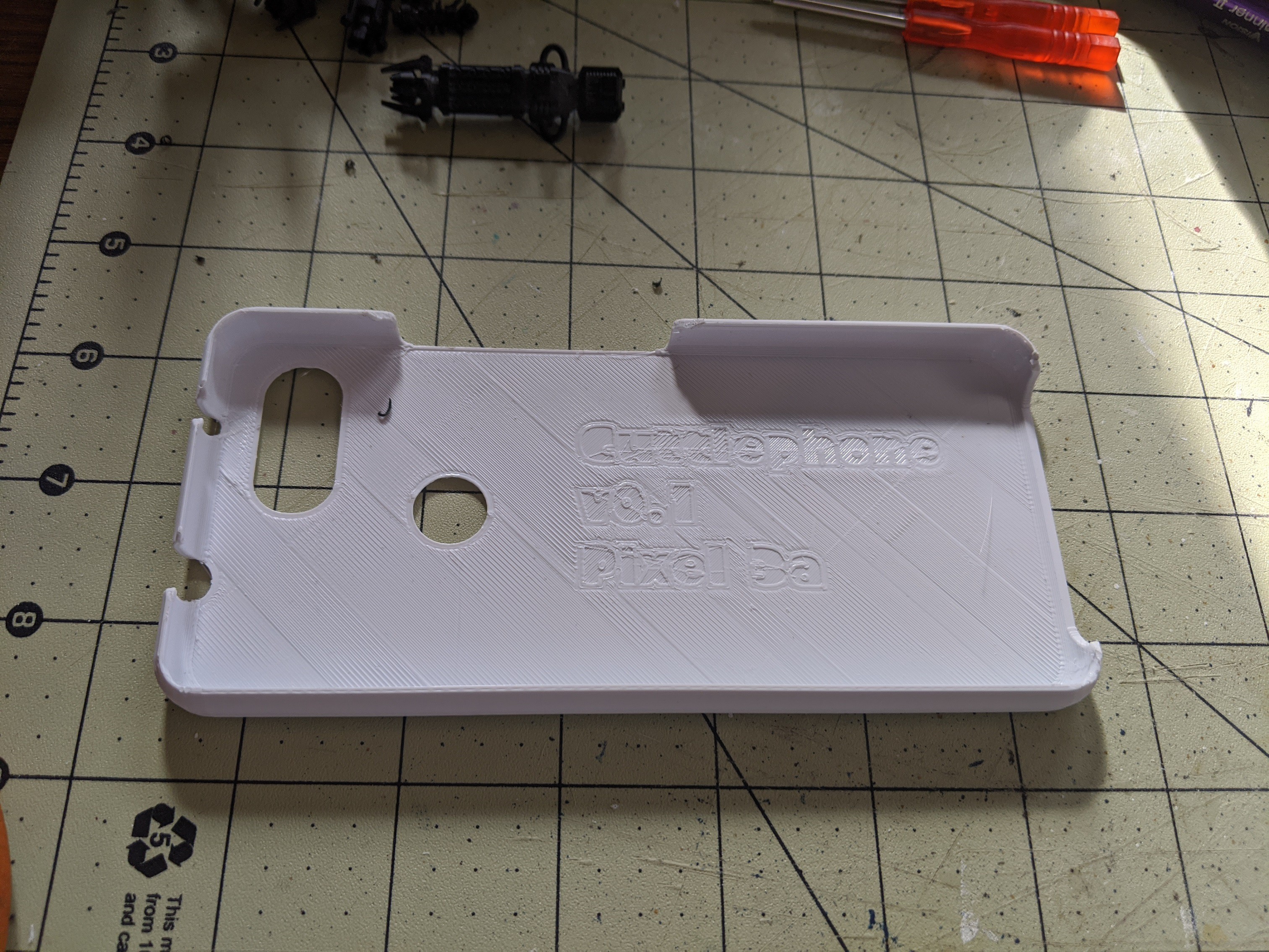 It looks similar but performs much better.
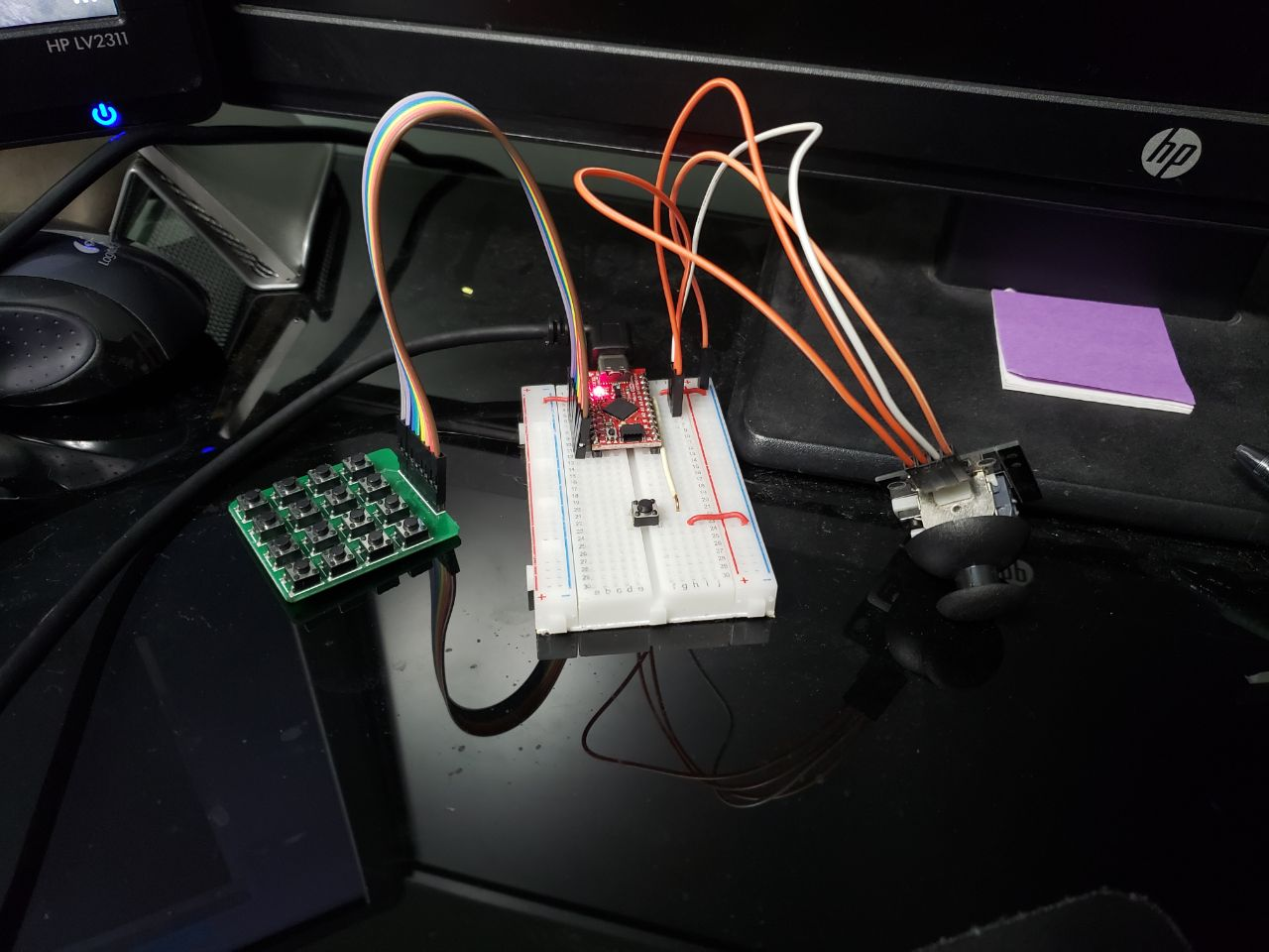
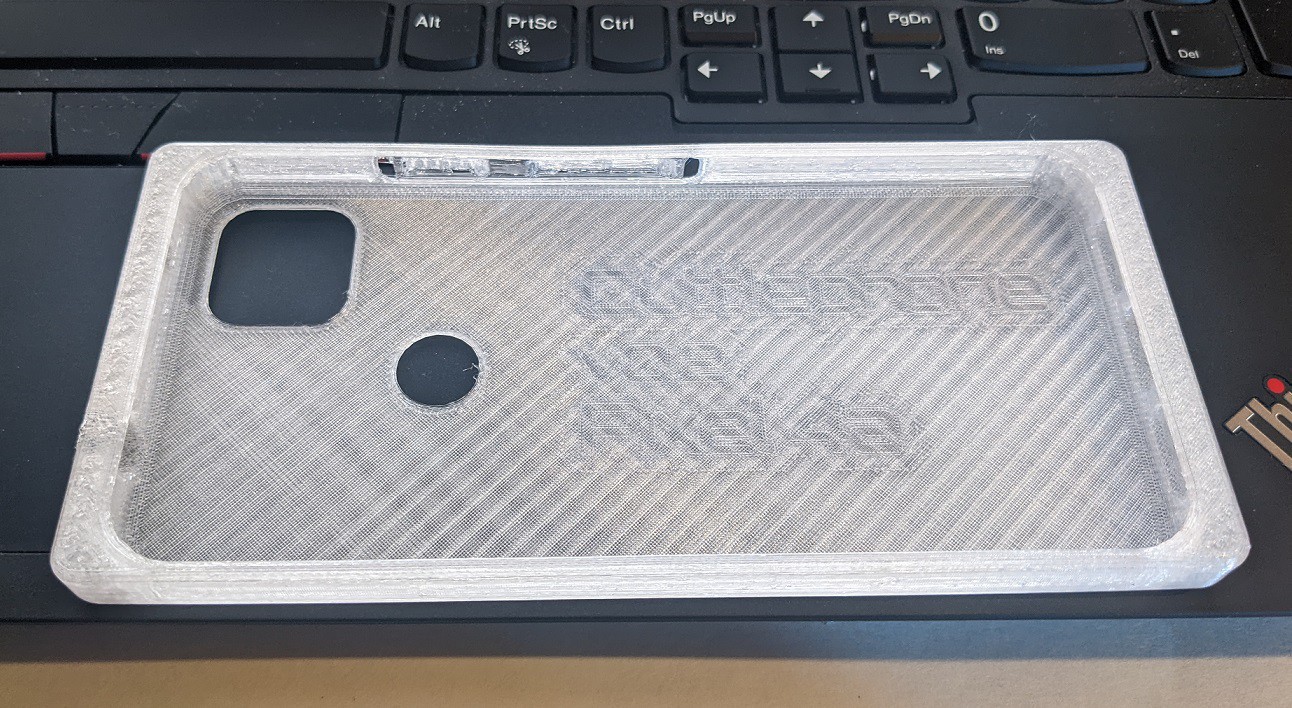
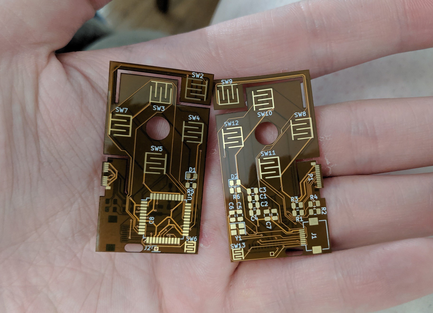
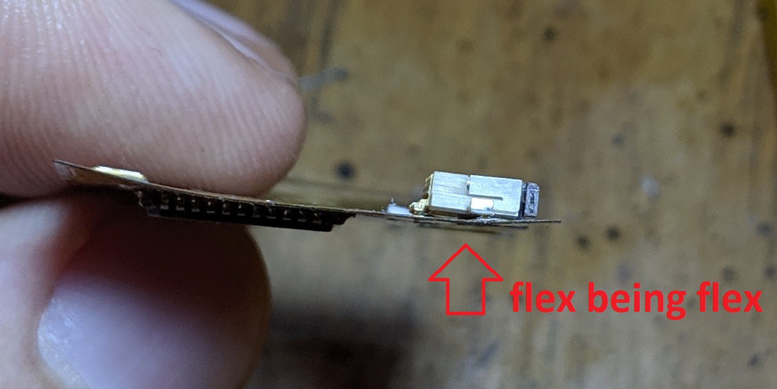
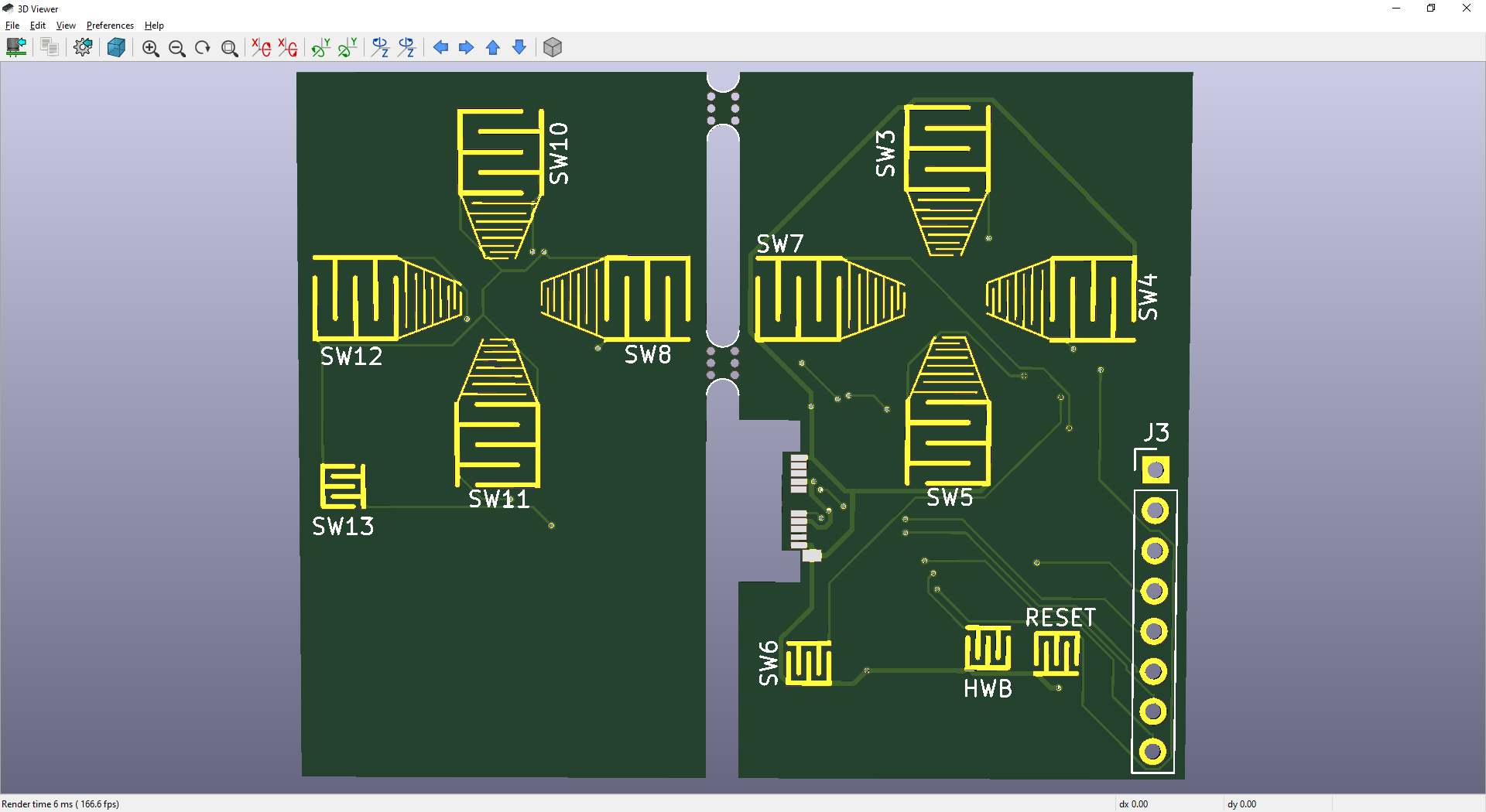
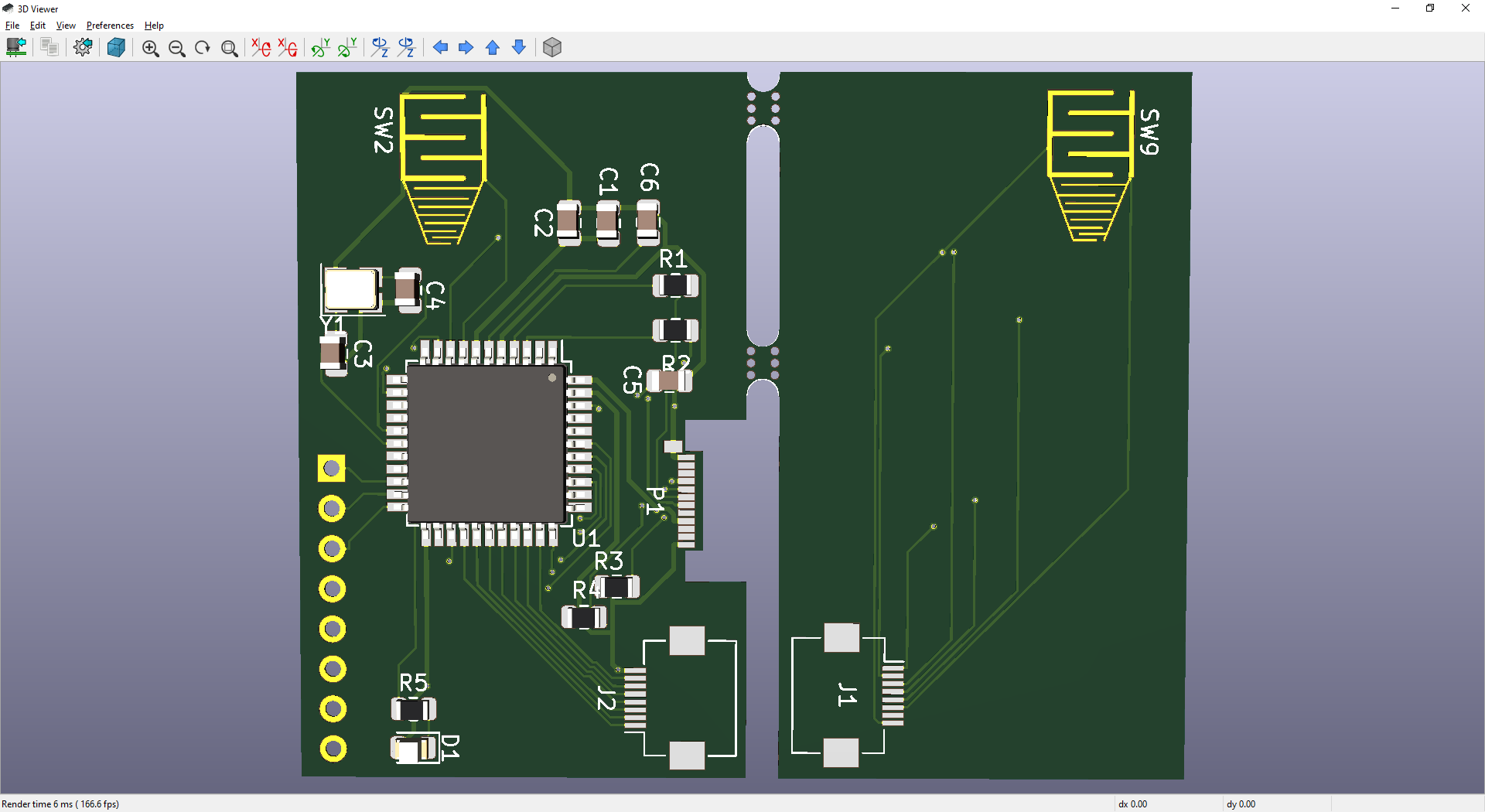
 Old gamepad PCB sitting in the last print the CEL Robox was able to achieve. This version had several overhang issues in the 3d model that I've fixed. Phone fit was also whack.
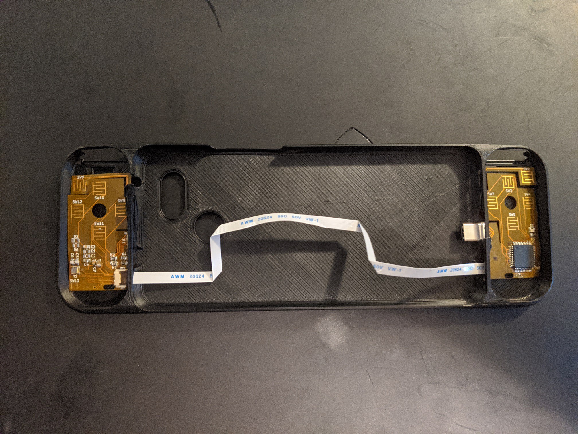
 Phone case simply has no gamepad features.
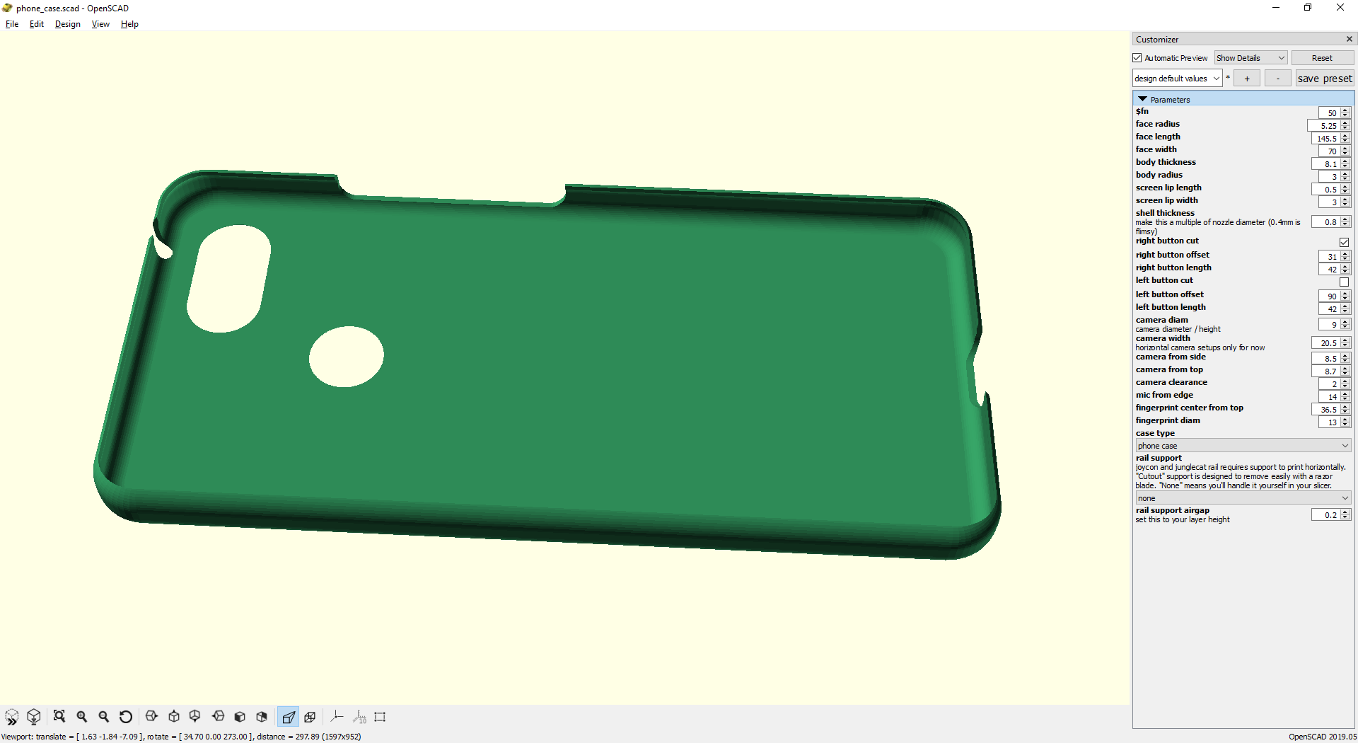
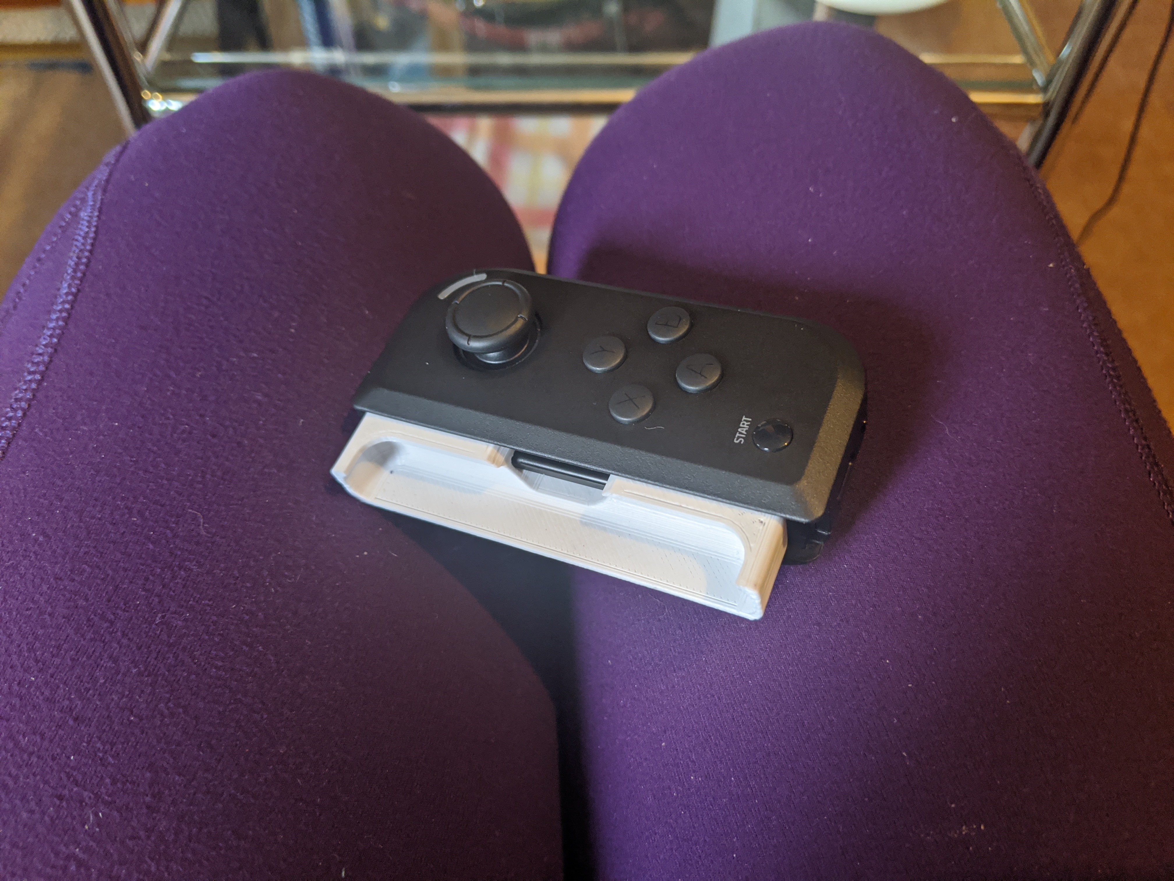
 The case works. Unfortunately many emulators (RetroArch, PPSSPP) don't support input from 2 devices at once. Dolphin emulator handles it though. On top of that, my phone gets the infamous Joy-Con lag which makes these unusable until I can find a patch.
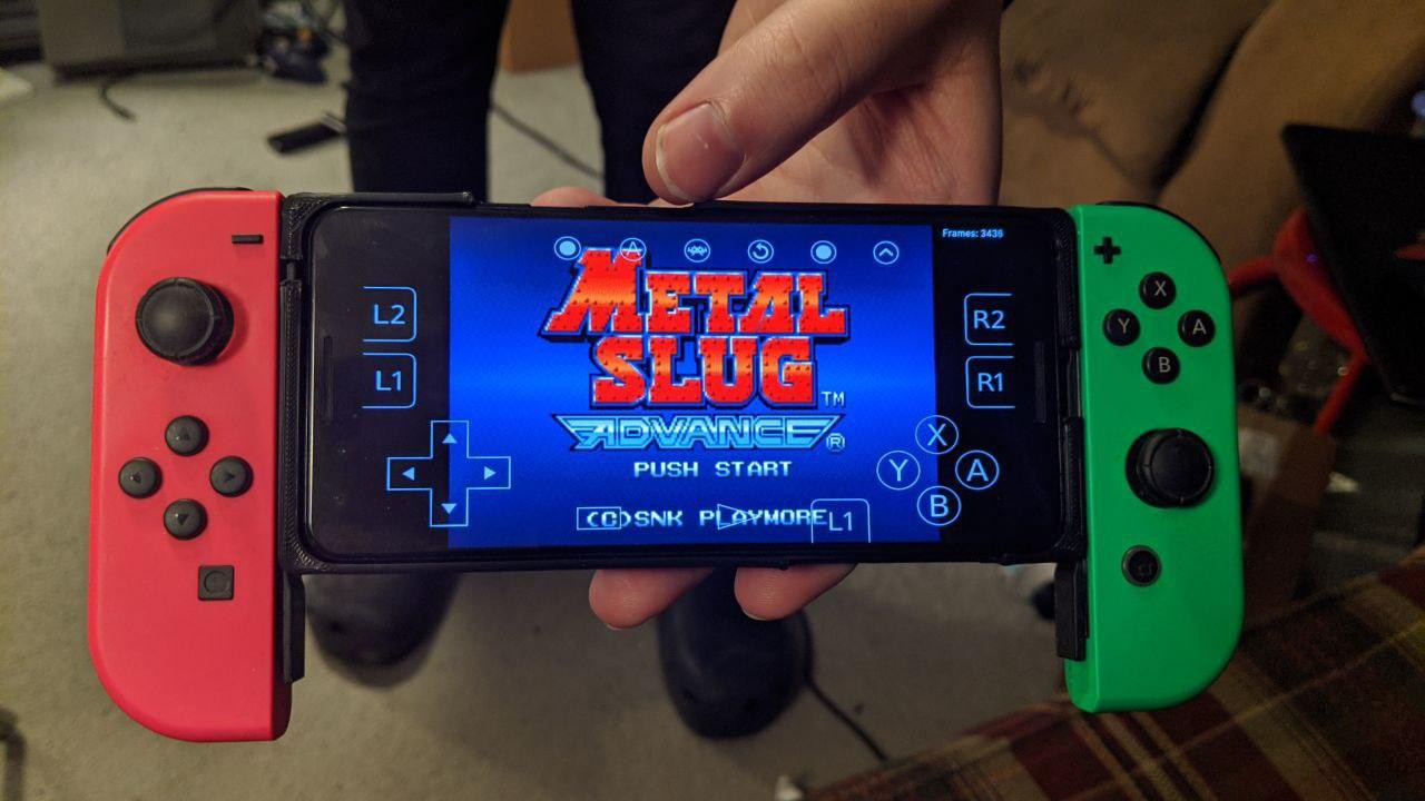


 Andrey Kalmatskiy
 Peter Lyons
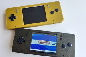
 Miroslav Zuzelka
 Ben Holmes
It's funny. Around the time you posted this project, I was working on this exact idea. I'm no electrical engineer so the extent of my knowledge (for now) is limited. I used dmadison's ArduinoXInput library on GitHub with a Teensy LC to communicate with my phone via USB-C. It only went as far as the breadboard stage with one button and one analog stick.