 Miroslav Zuzelka
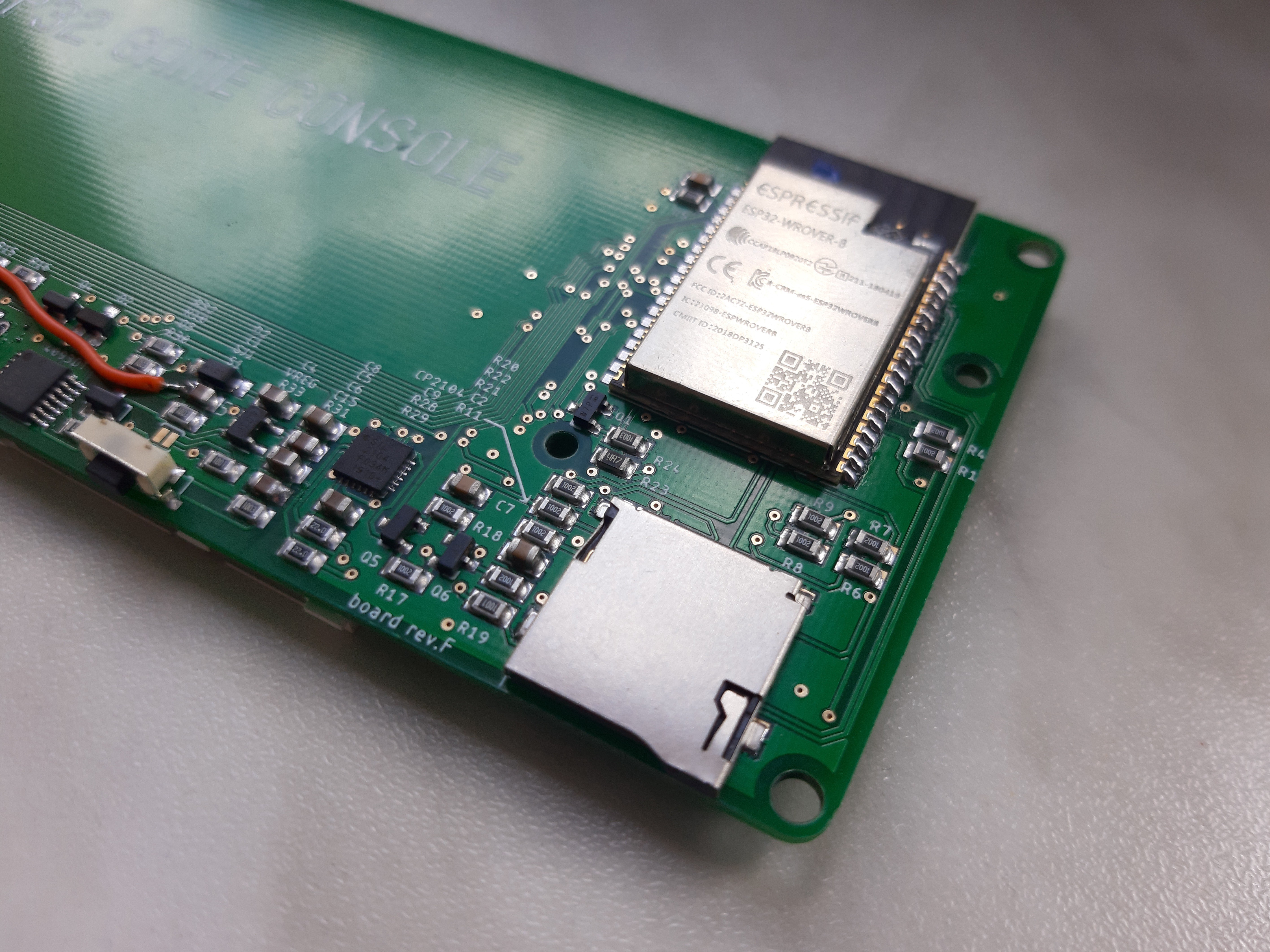
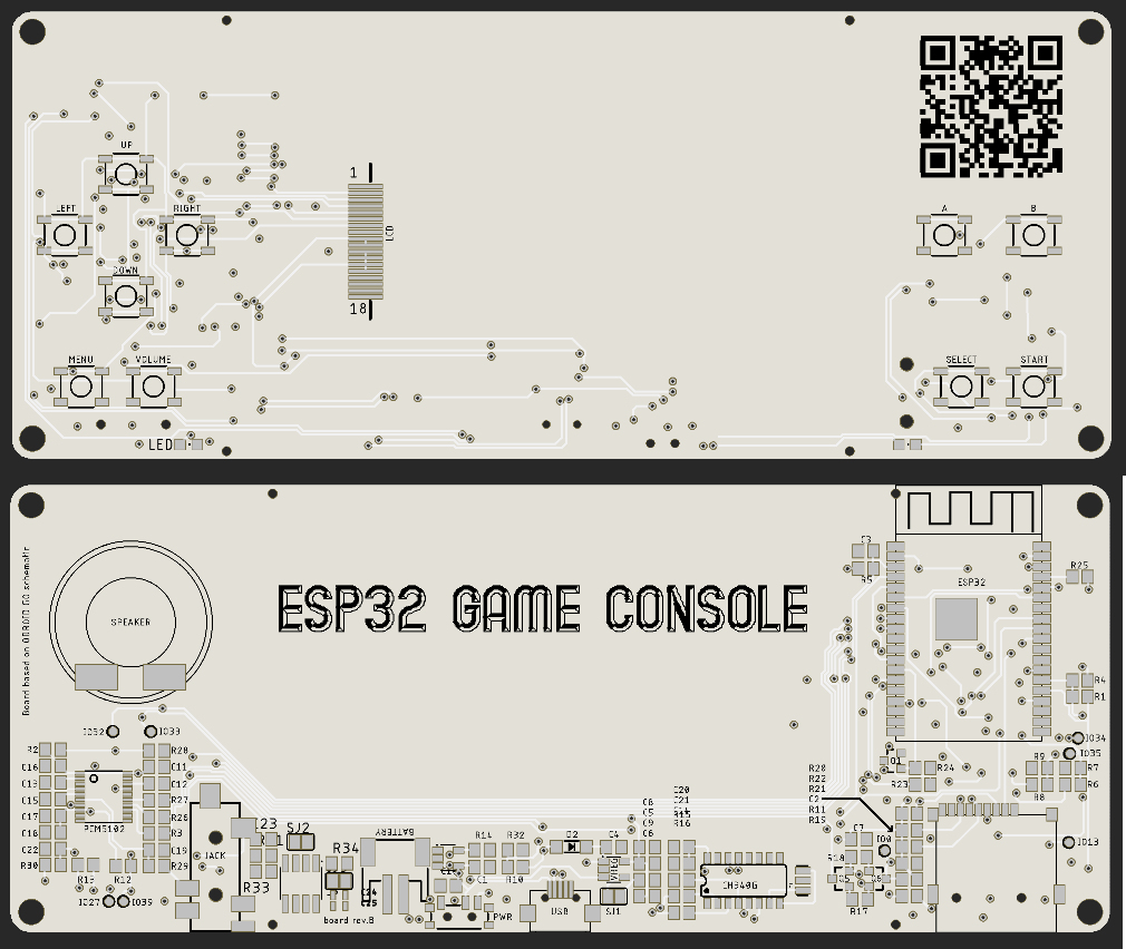
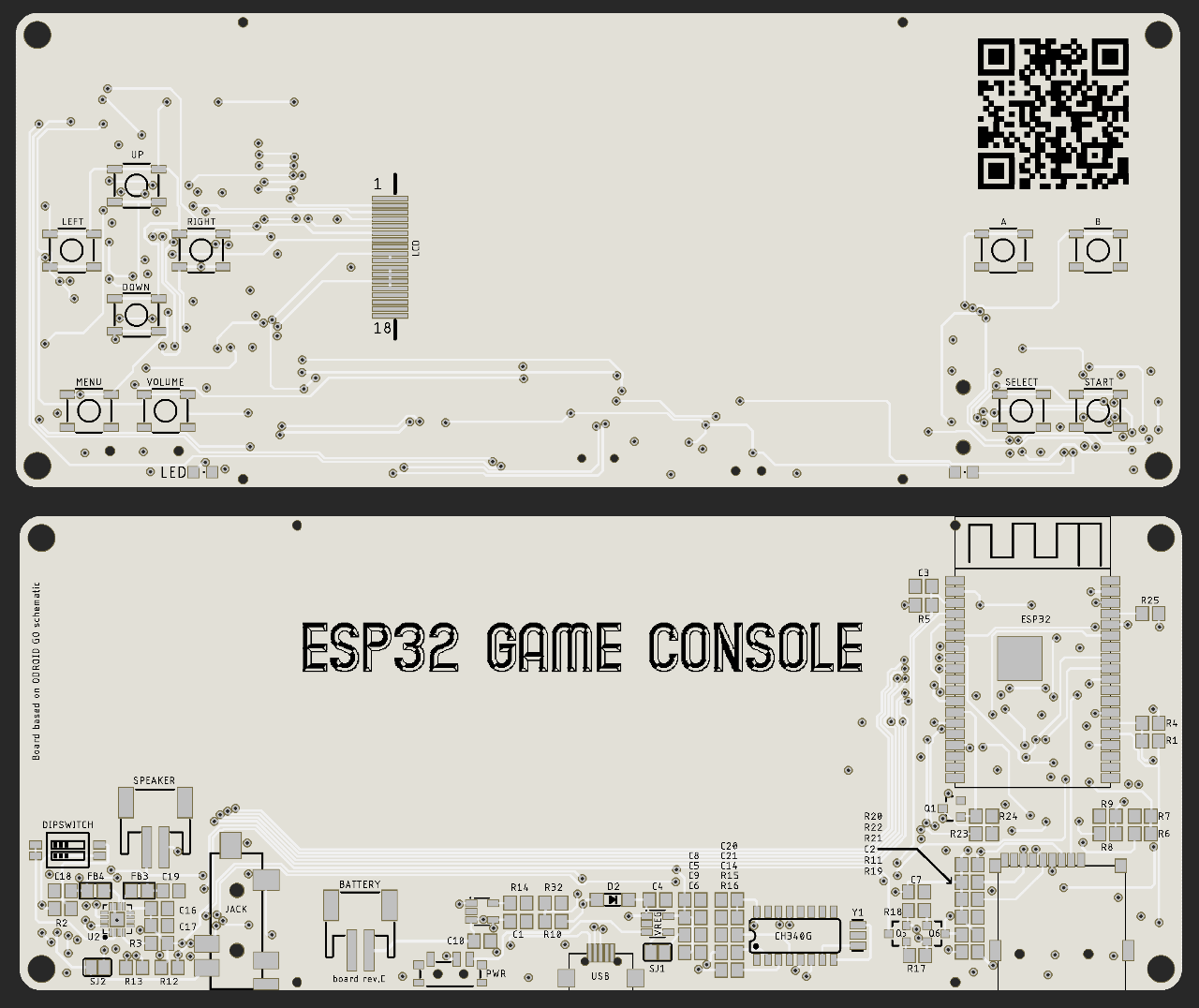
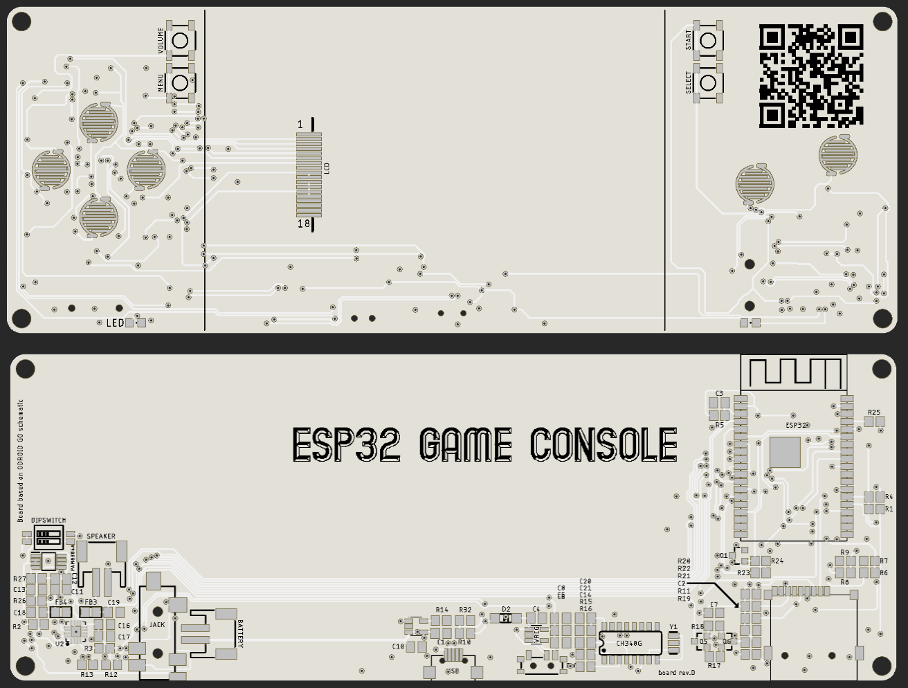
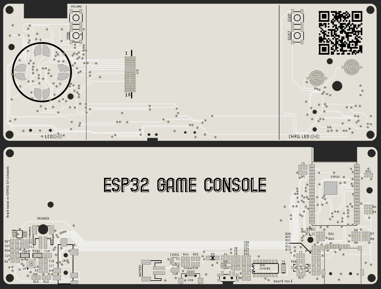
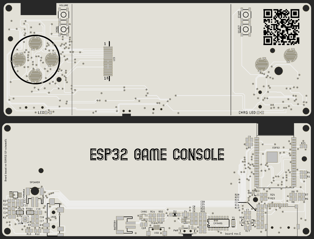
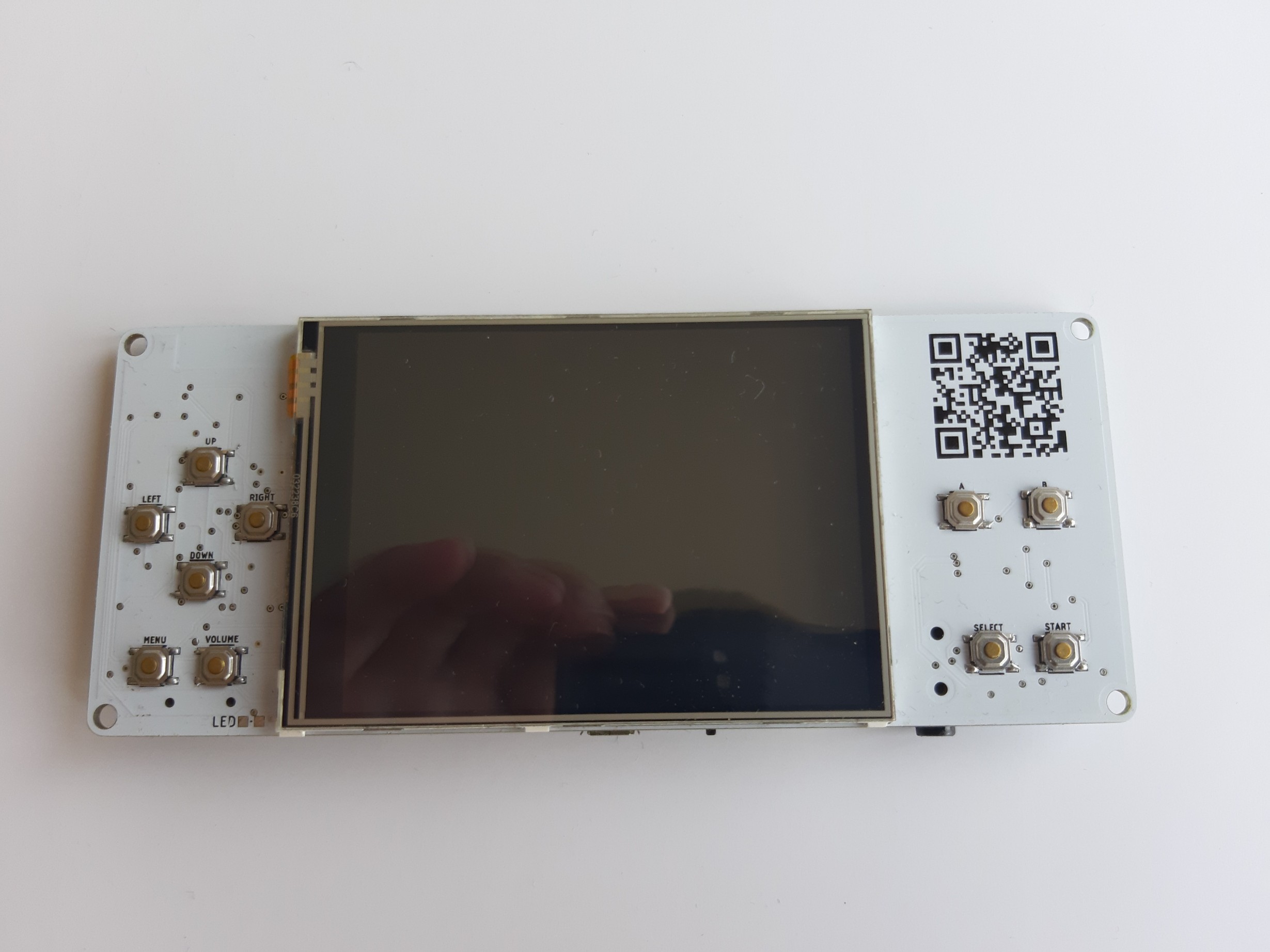
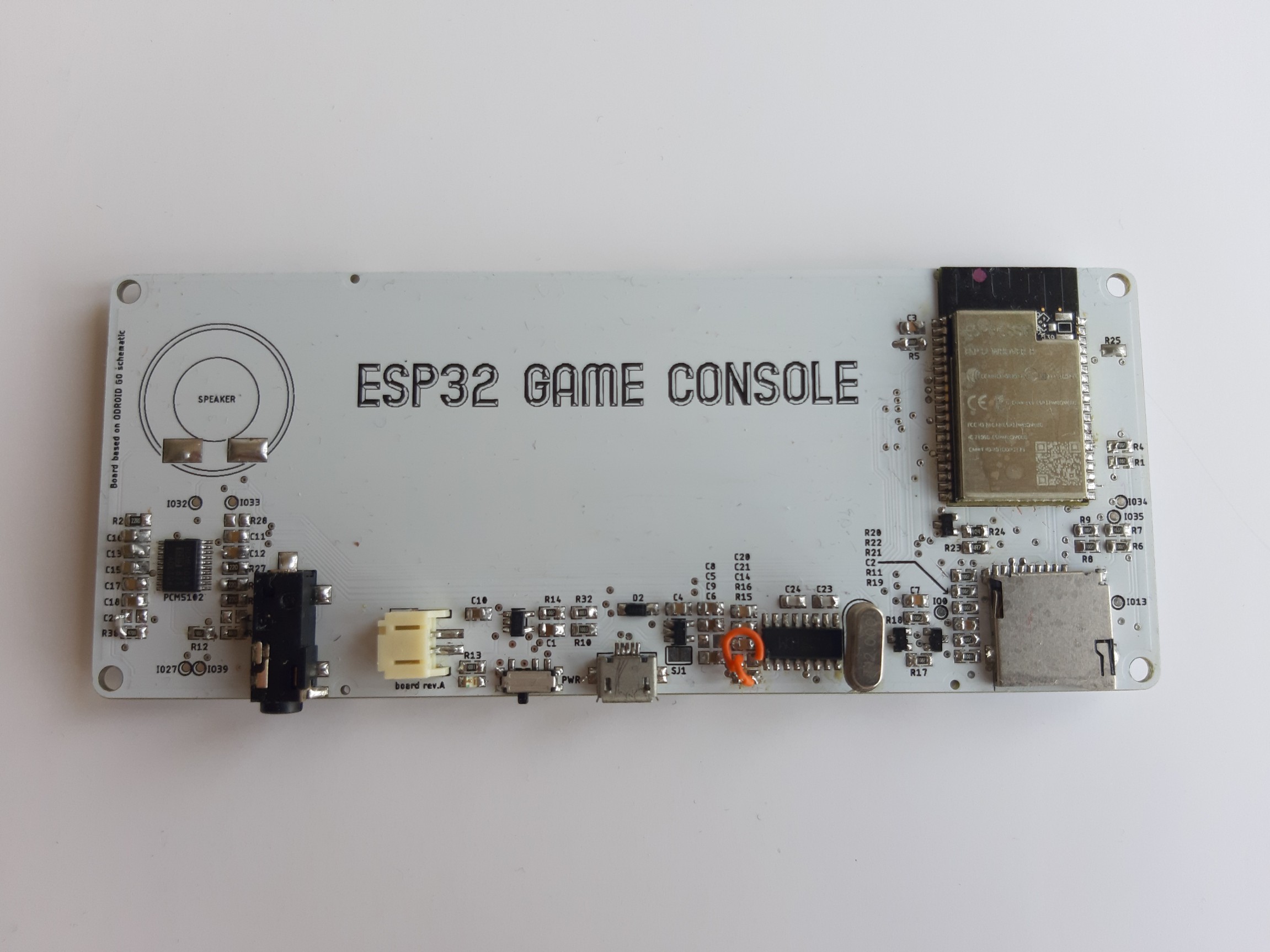
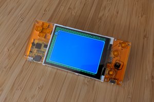
This is should be direct clone of Odroid Go (fully compatible) with some added features:
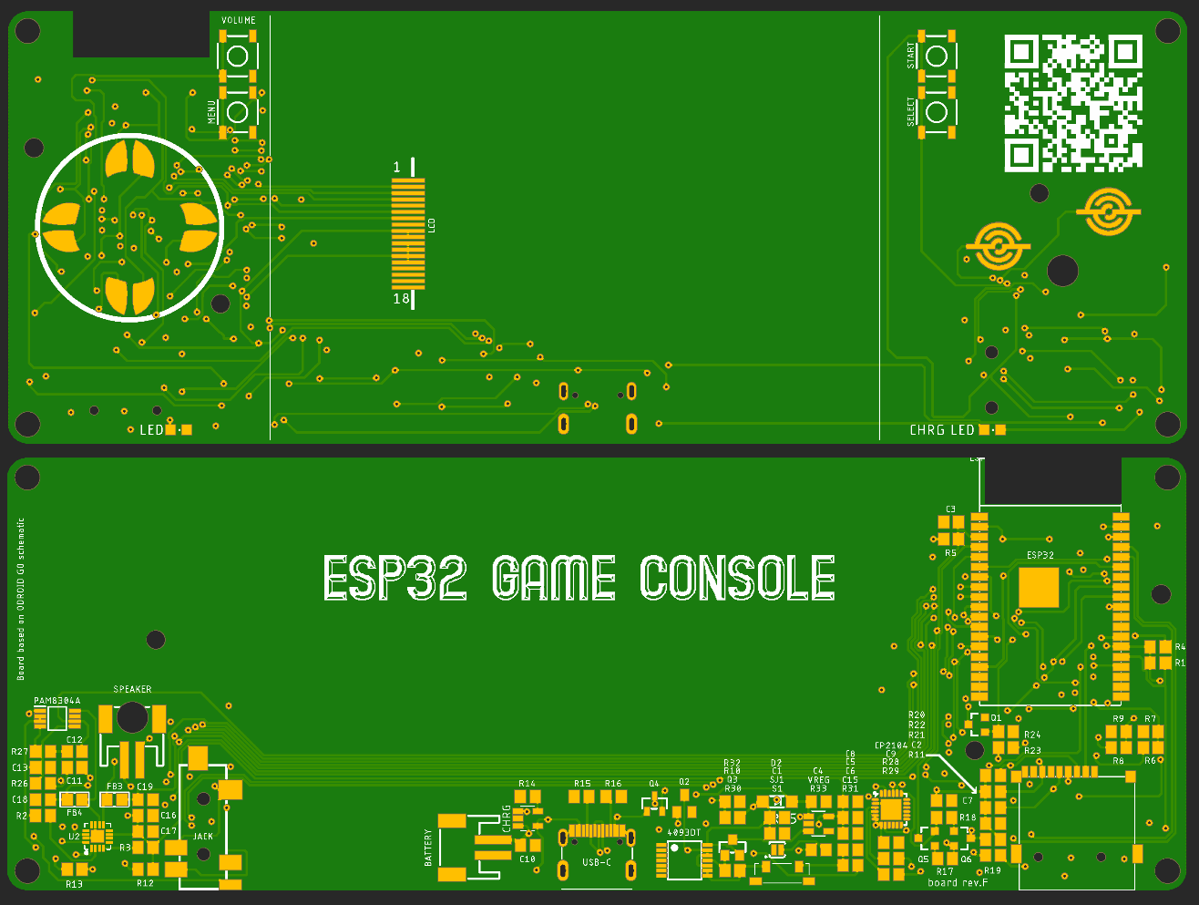
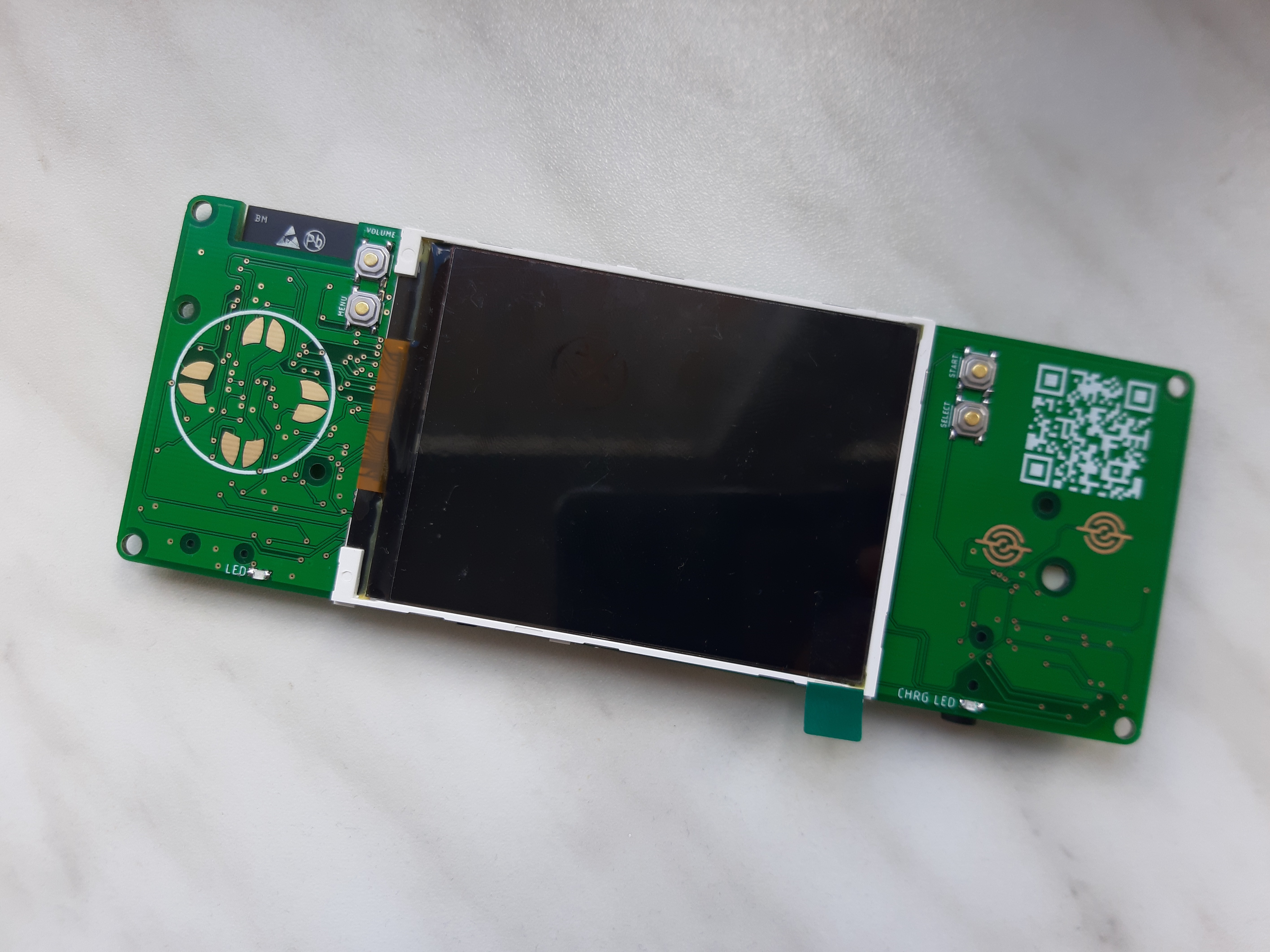
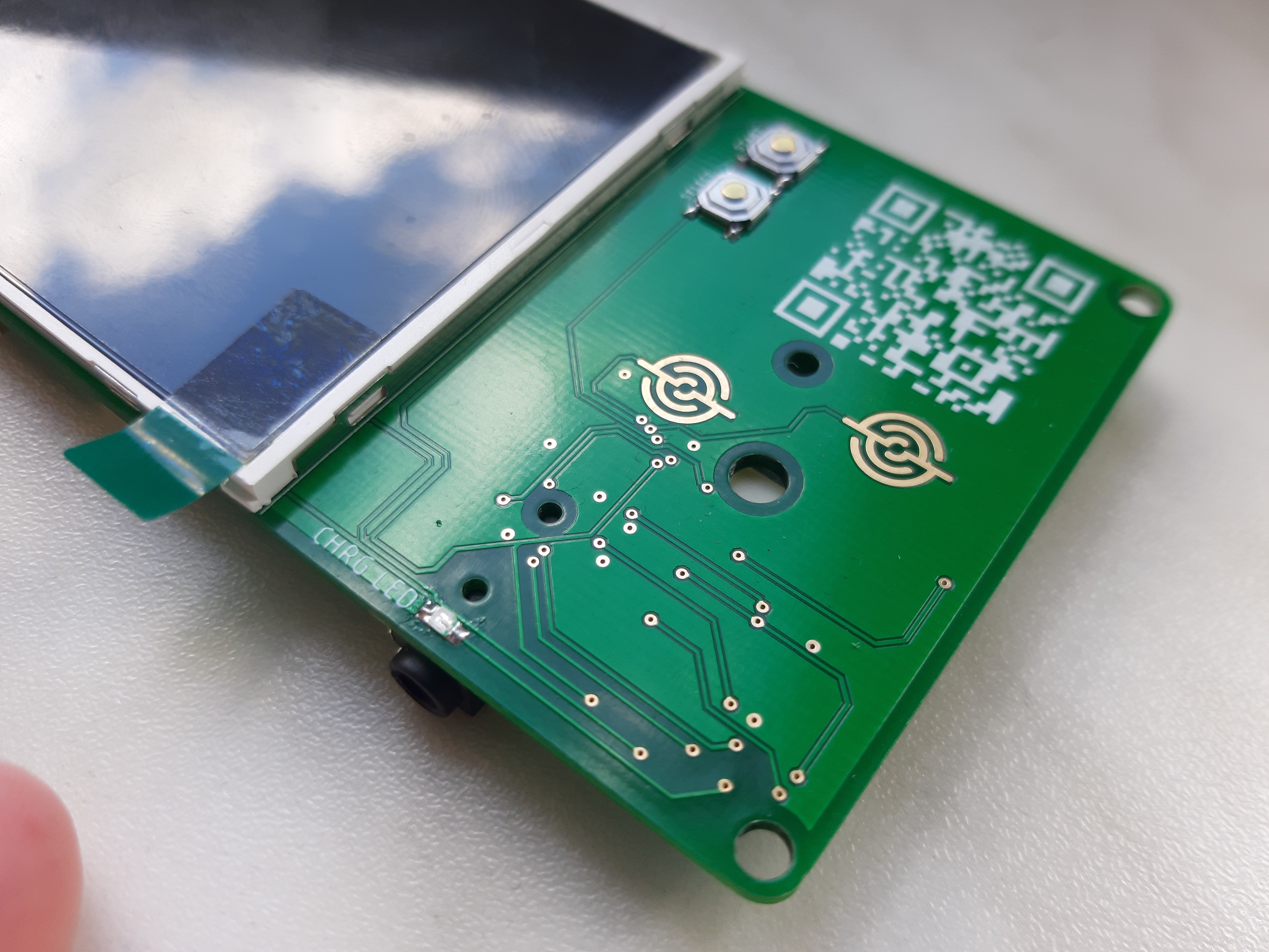
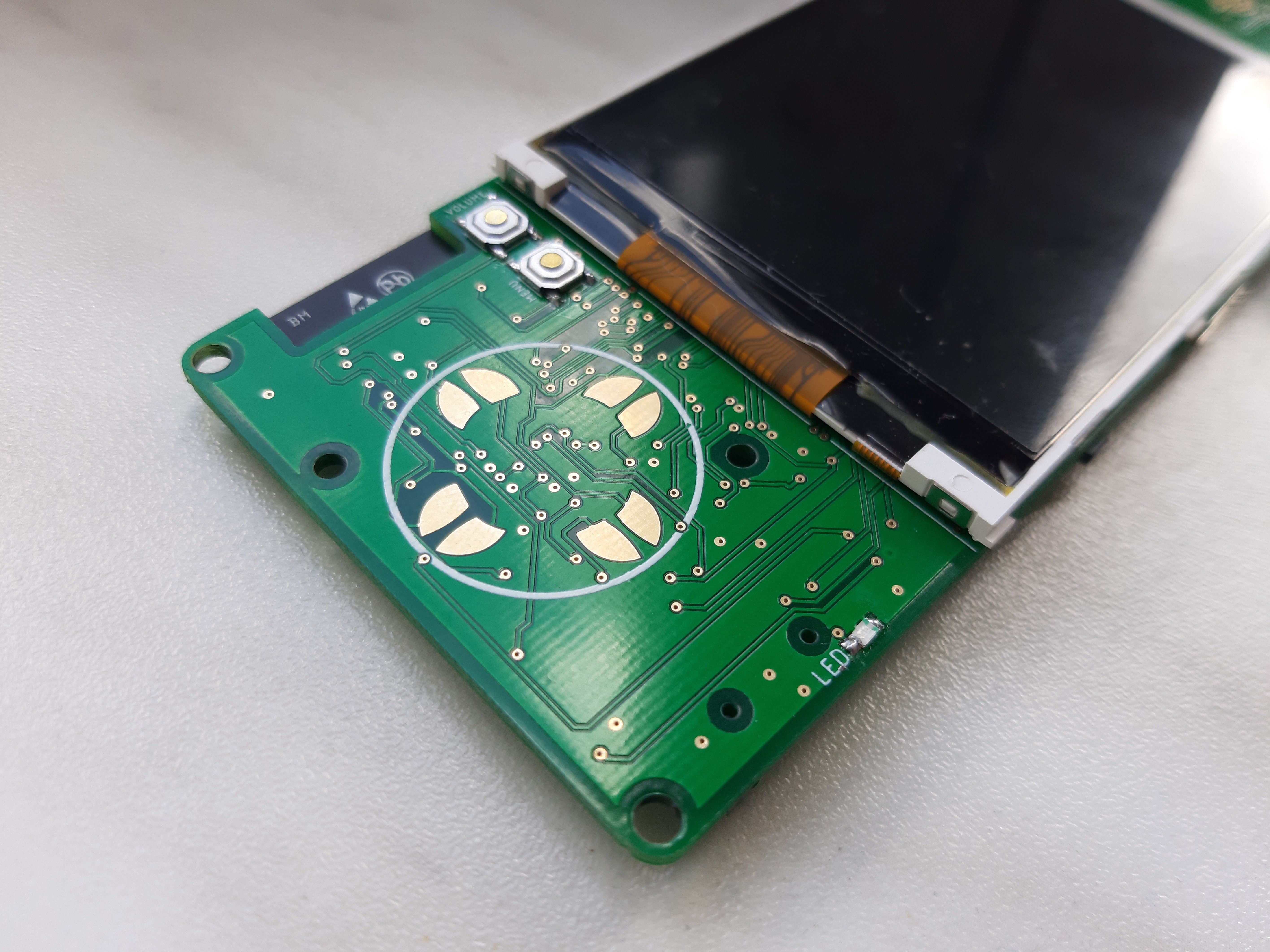
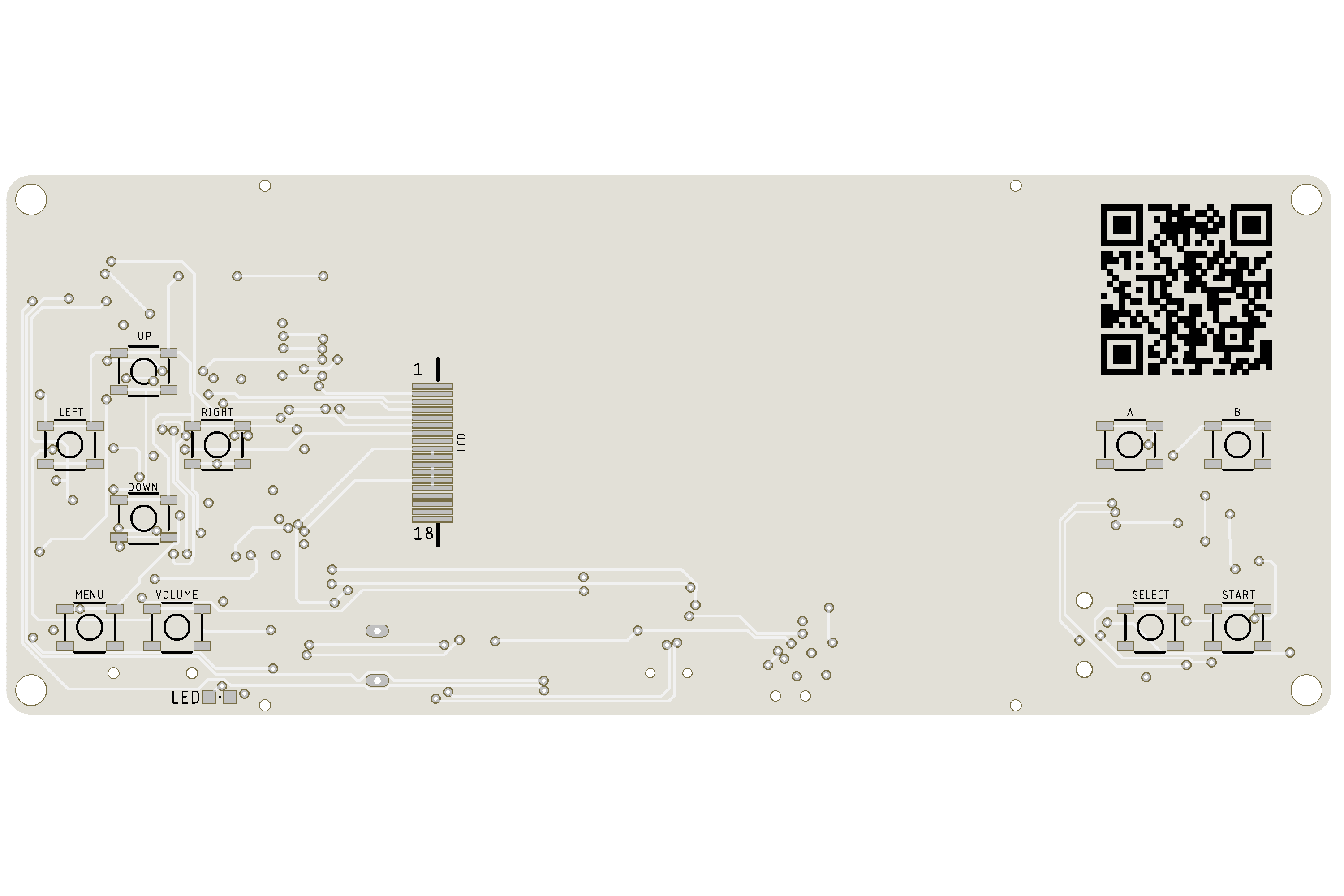
- 3.2" ILI9341 TFT LCD
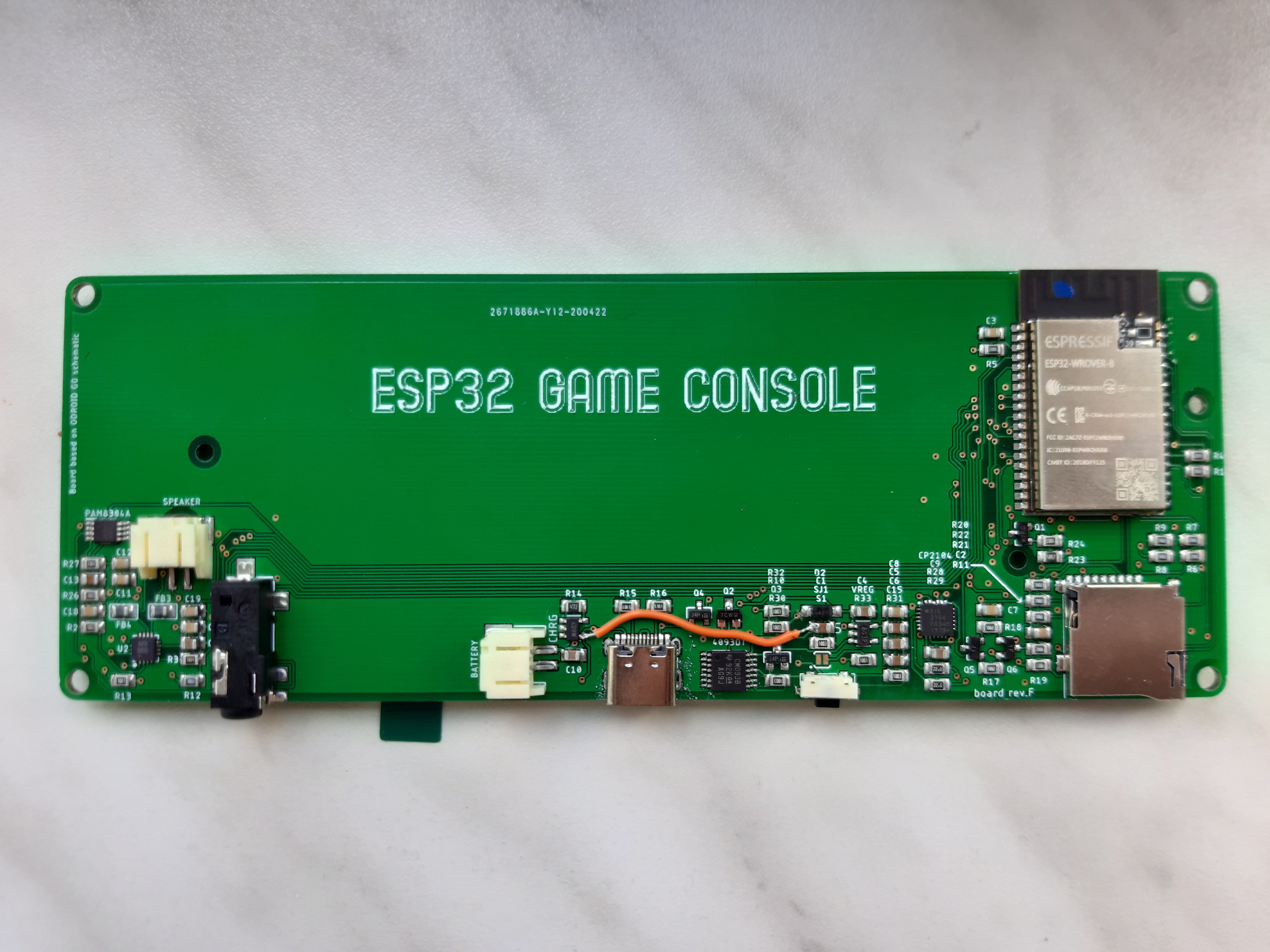
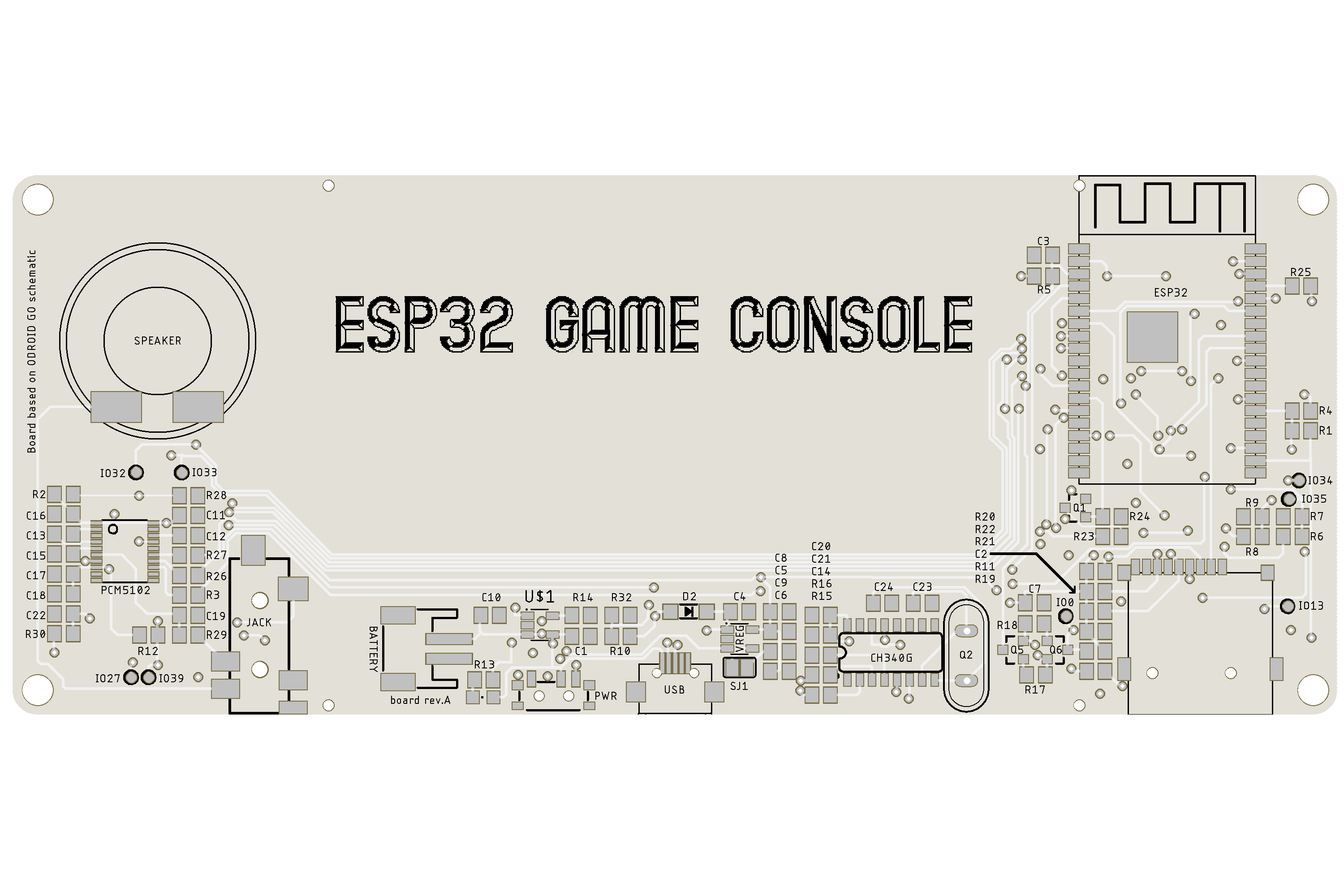
- ESP32 WROVER with PSRAM (16MB)
- micro SD card
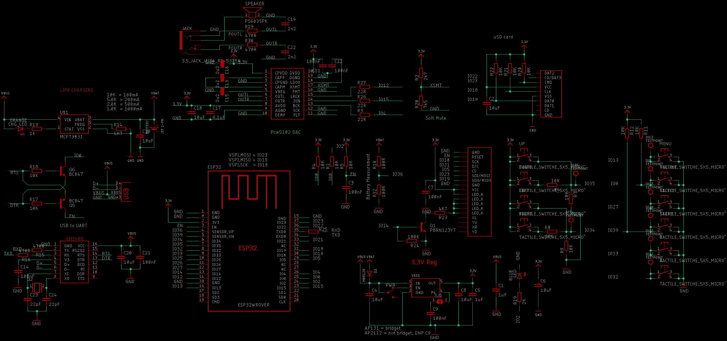
- built-in charger based on MCP73831
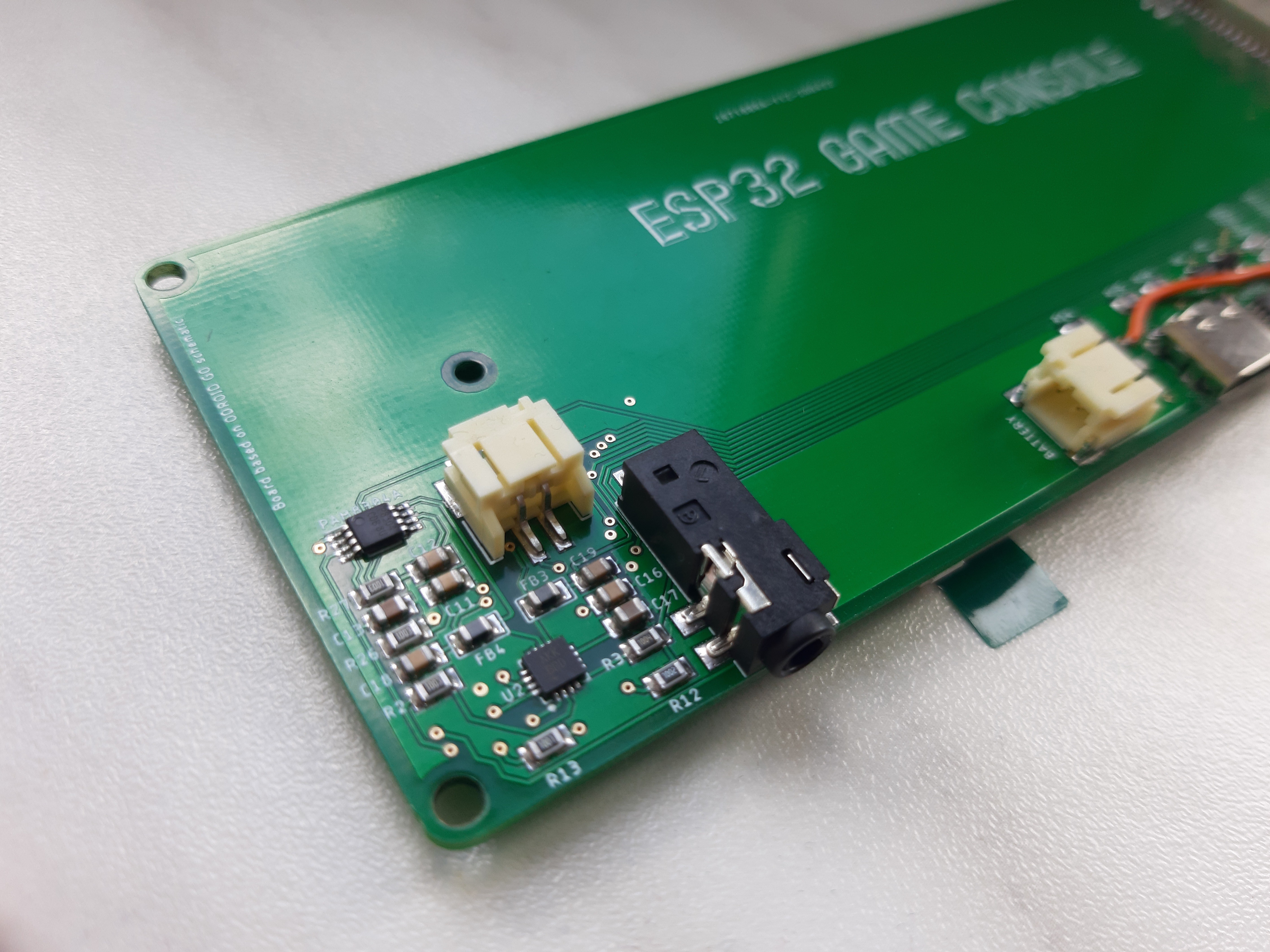
- integrated audio through PAM8304
- integrated I2S audio through MAX98357 (early version was with PCM5102)
- 3.5 mm audio jack
- 2000 mAh Li-Po battery
- USB to UART via CH340G
This game console can be programmed with examples from Odroid Go library or you can use this library to program your own games. This can also be used with Micropython.

 deʃhipu
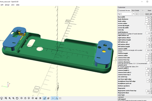
 Maave
Maave
In case anybody else is wondering: the schematic and PCB Eagle project, and STL files for the housing can be found at https://github.com/dronecz/esp32-game-console