 Jacob Still
Late last year, I found Mohit Bhoite's instagram. He had posted a picture and video of an HP 5082-7415 that he was going to use in a project. This prompted my unnecessarily large order of all sorts of vintage LED displays including an HDSP-2111, a couple TIL311s, and many more.
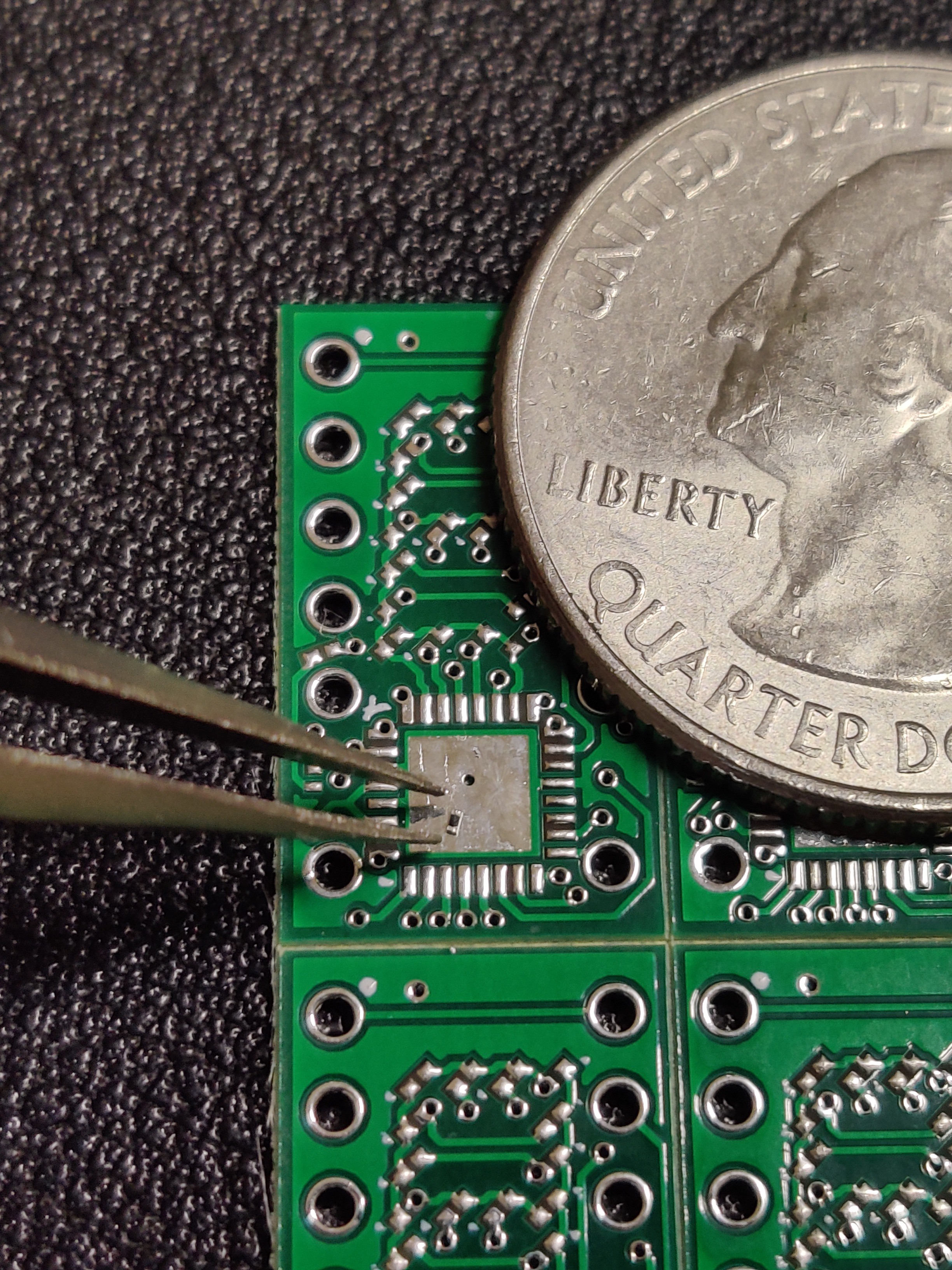
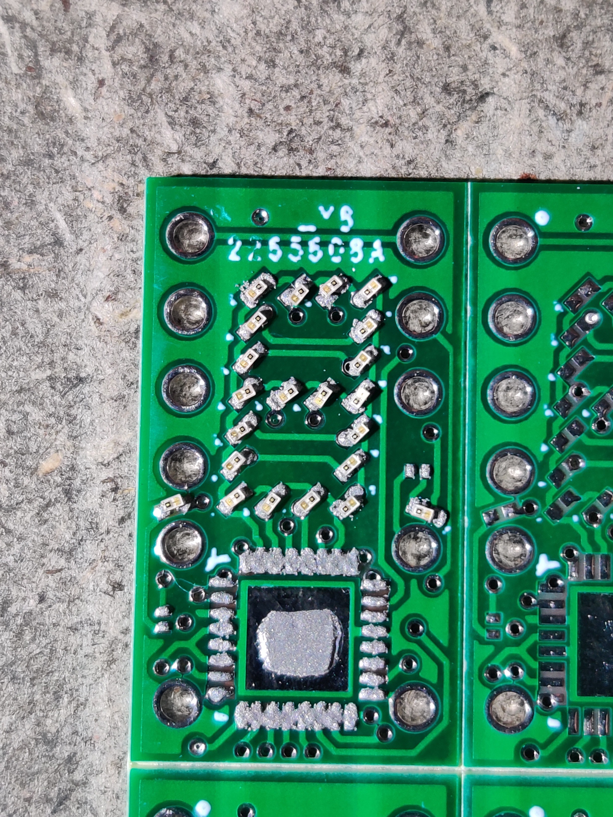
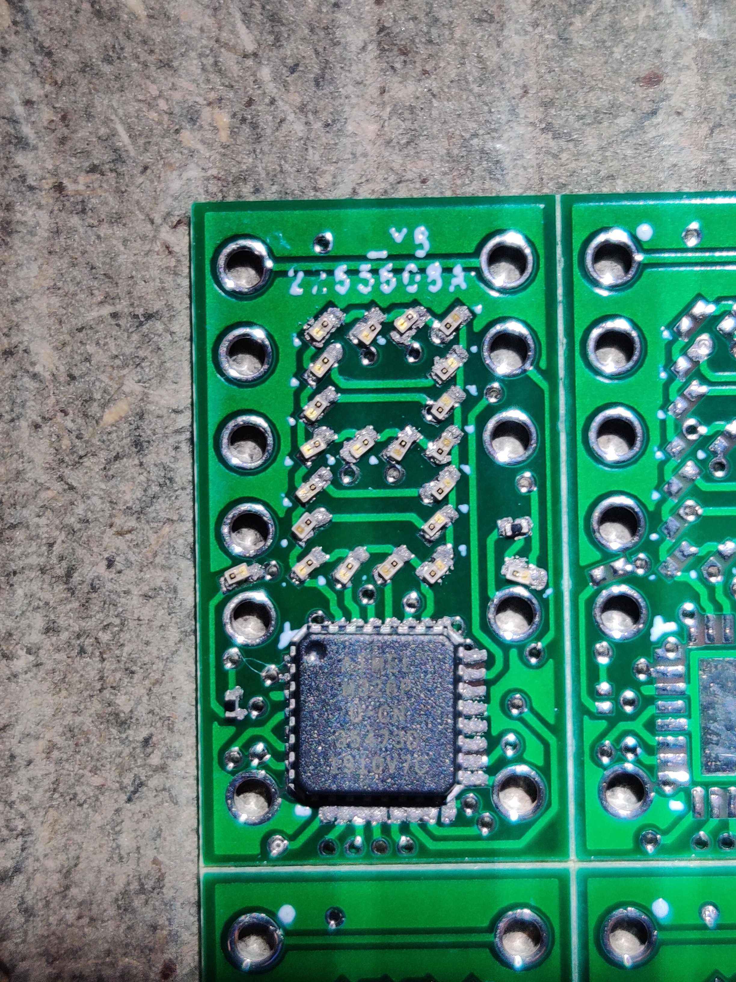
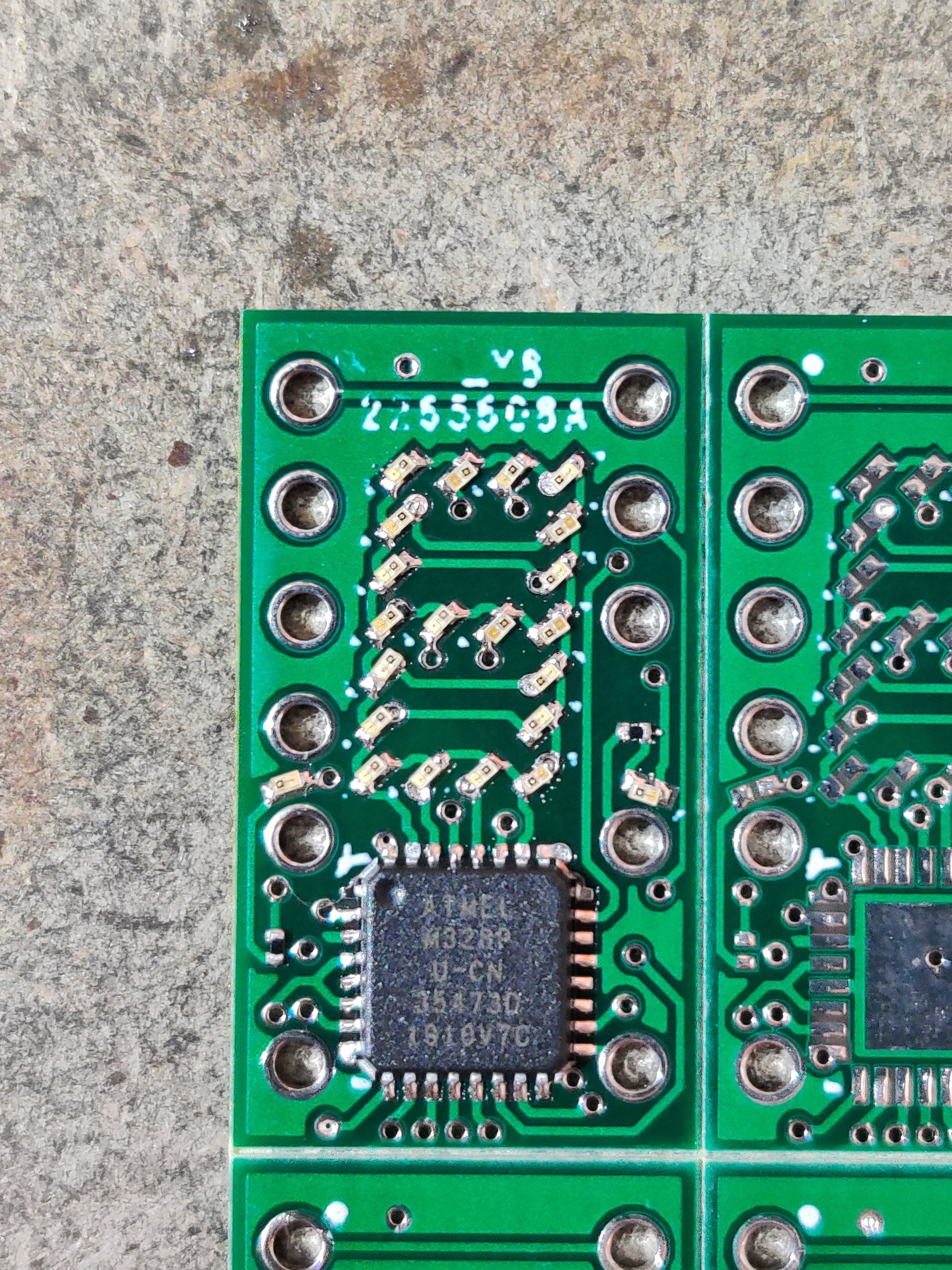
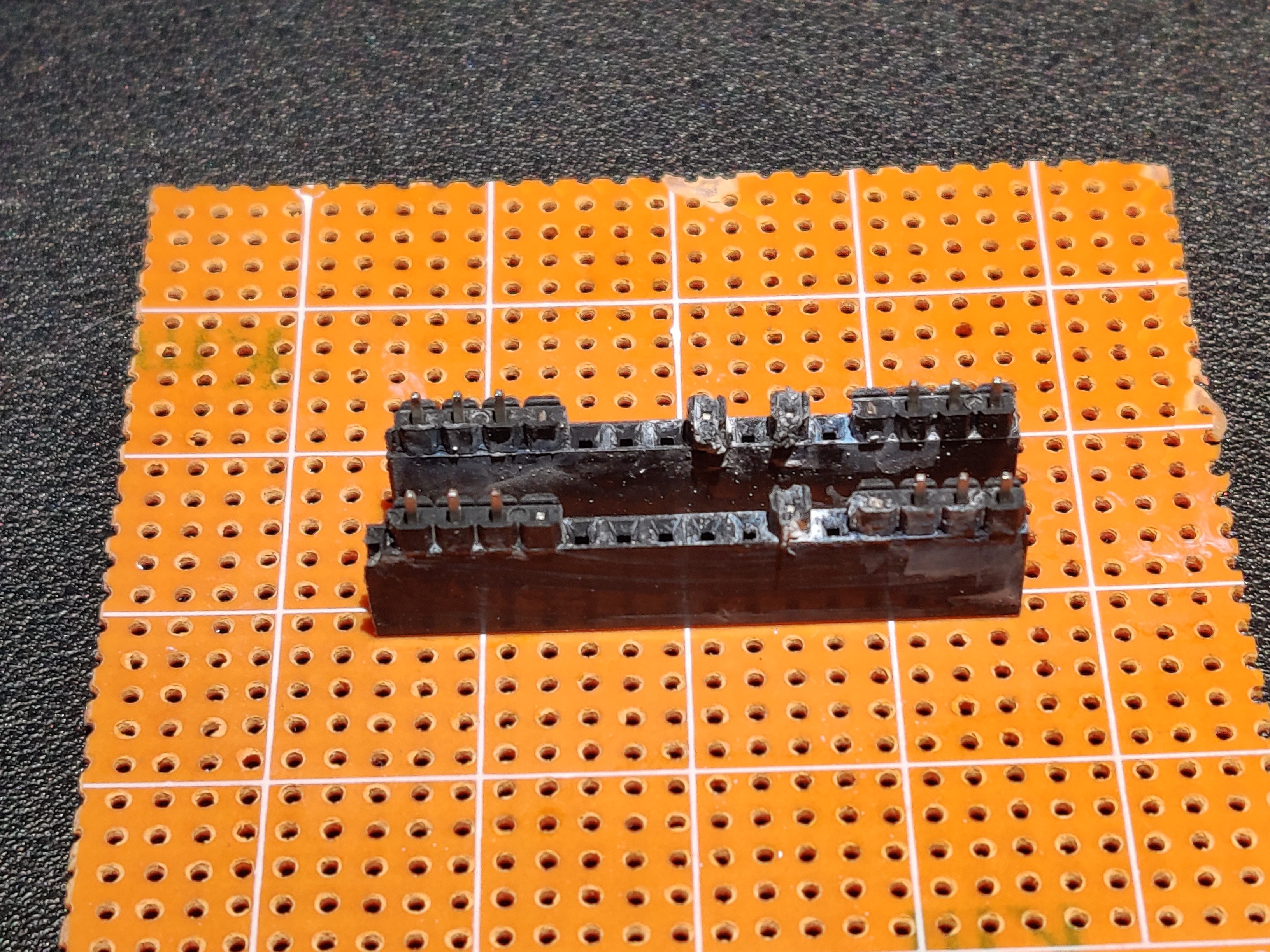
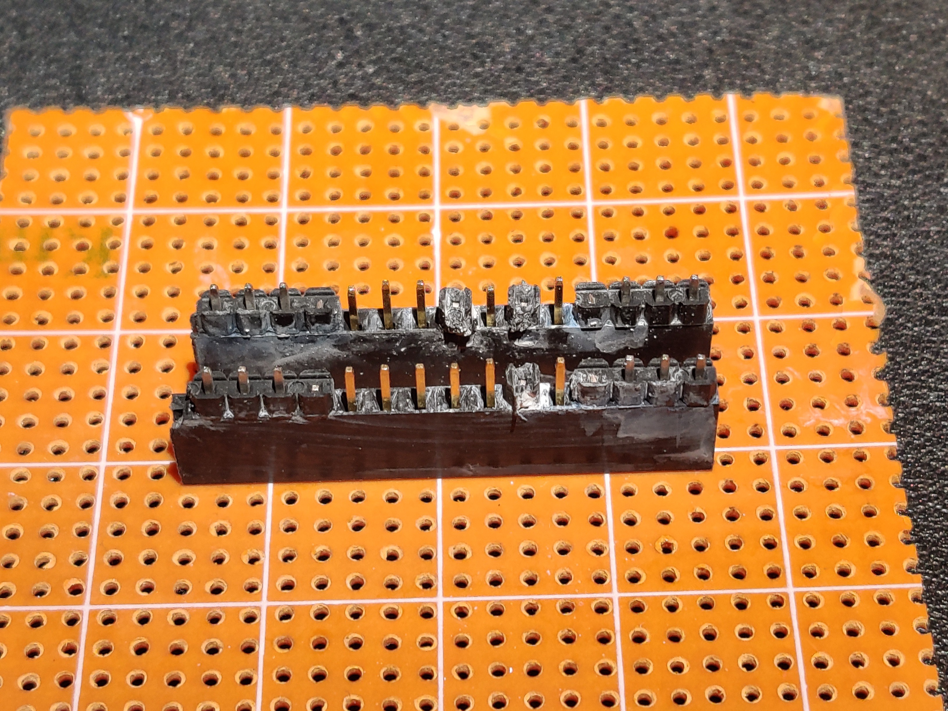
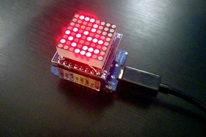
At the beginning of this year, I stumbled upon Mile's instagram page. At the time, he posted a picture of his DIYTIL305. This inspired me to do my own sort of display board. I decided to do a reprogrammable TIL311 replica.
I didn't really have time to do anything on this because of school and work. Now with school done, I have begun work.
BTW, only at the time of writing this did I find that Mile's project is based on Alex's and Yann Guidon / YGDES's PICTIL project. Thanks to all of you who inspired this long endeavour.


 arduino nano")

")
")


 deʃhipu
 Jackson Keating
 Wing Tang Wong
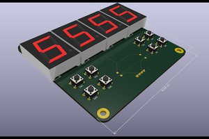
 Ken Yap
Love those retro display projects. Eagerly waiting for someone doing an affordable version of flip dots and nixie tubes. There are manufacturers (millclock.com, flipdots.com) but they're quite expensive.