 Alex
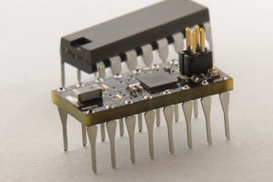
AlexThis project was original created by @Yann Guidon / YGDES out of frustration about this. Yann got some TIL311 to go forward in his project. The modules are cool for hobbyist projects but they have some issues. However it looks straight-forward to make such a module oneself, so why not DO it ?
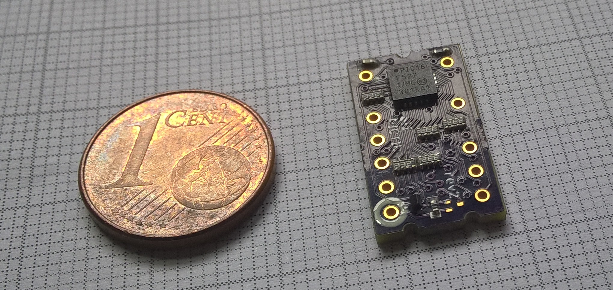
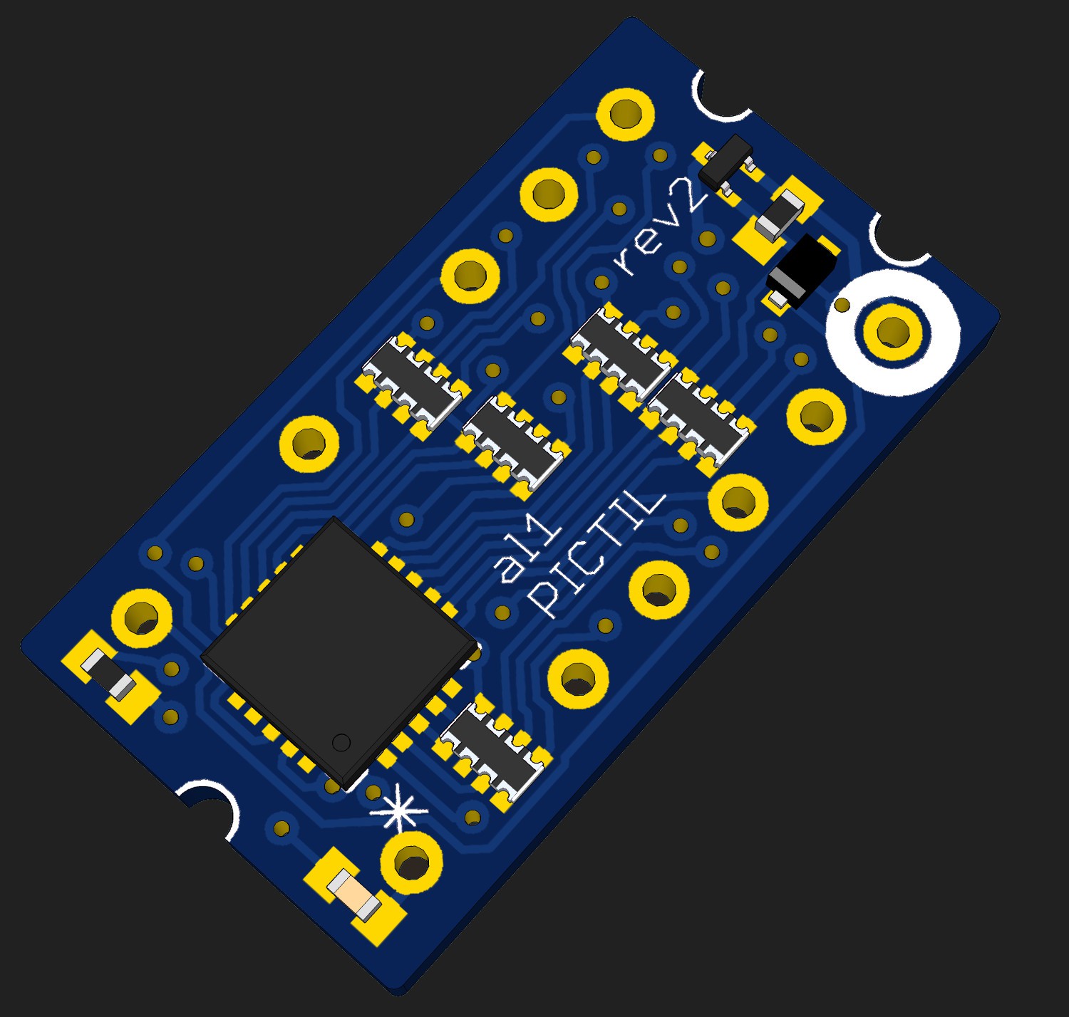
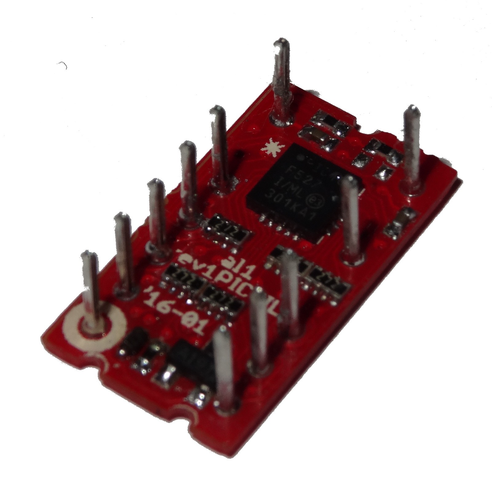
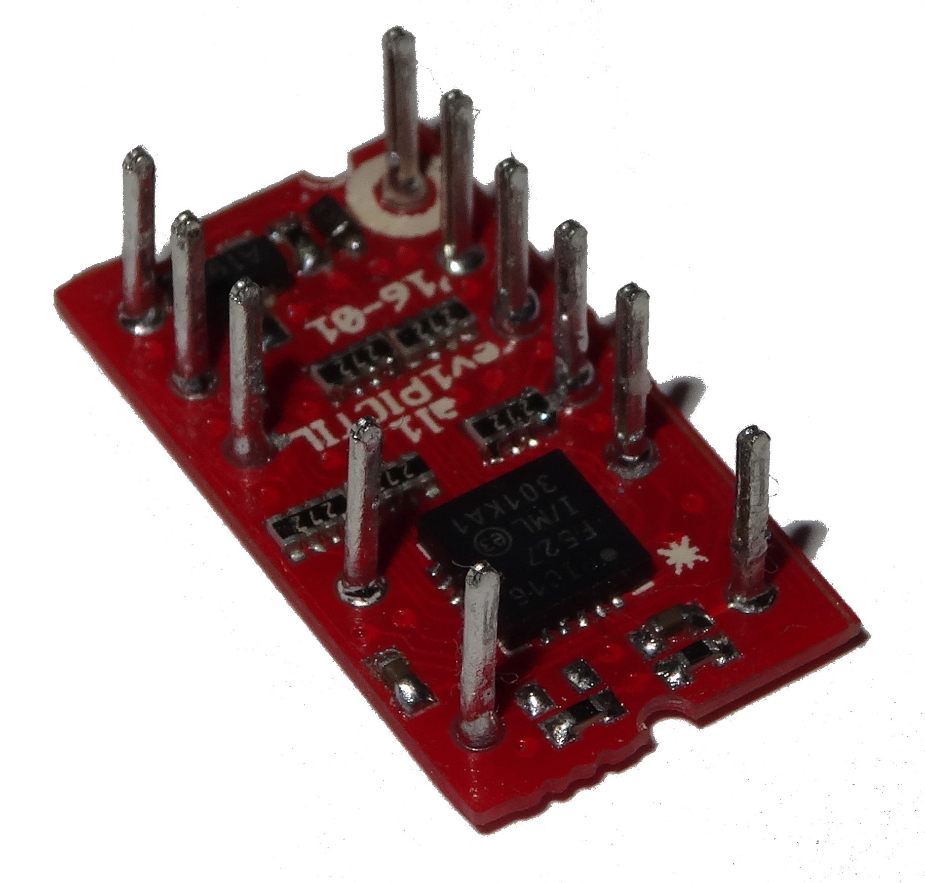
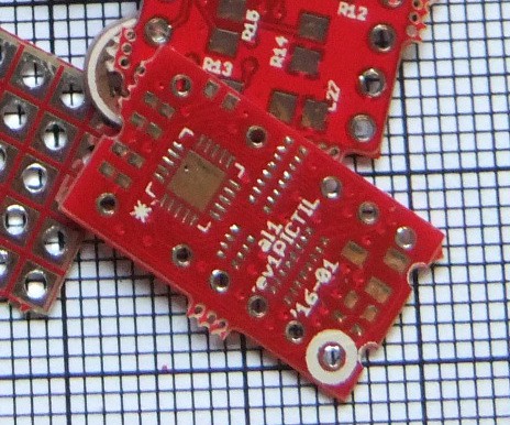
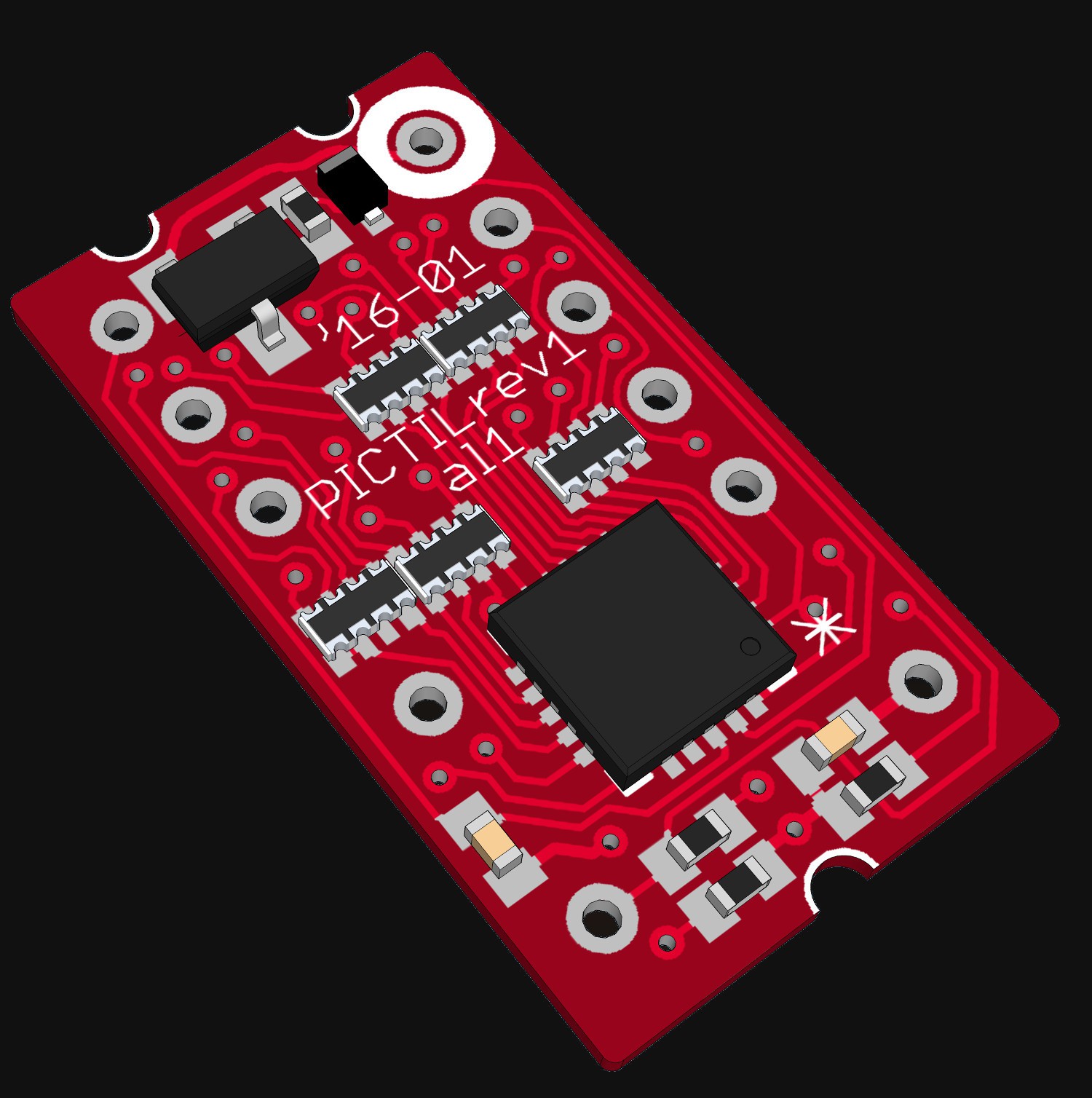
Out of the suggestions I ( @al1 ) joined this project. I had some fun designing this little PCBs. Some iterations can be found in the project logs and comments. The goal behind these PCBs to get a very similar replacement for the TIL311. The size of the PCB is the same and at least the pin mapping is similar (timing could be different). The PIC16F527 is a very good micrcontroller for this: Cheap and exactly the right number of IO.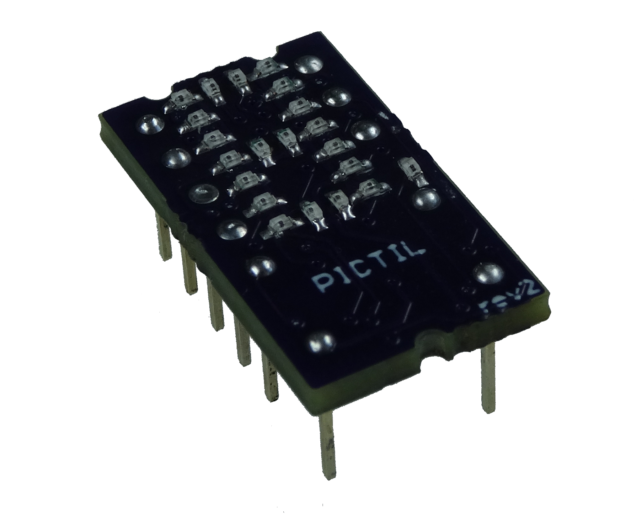
Something about the Hardware
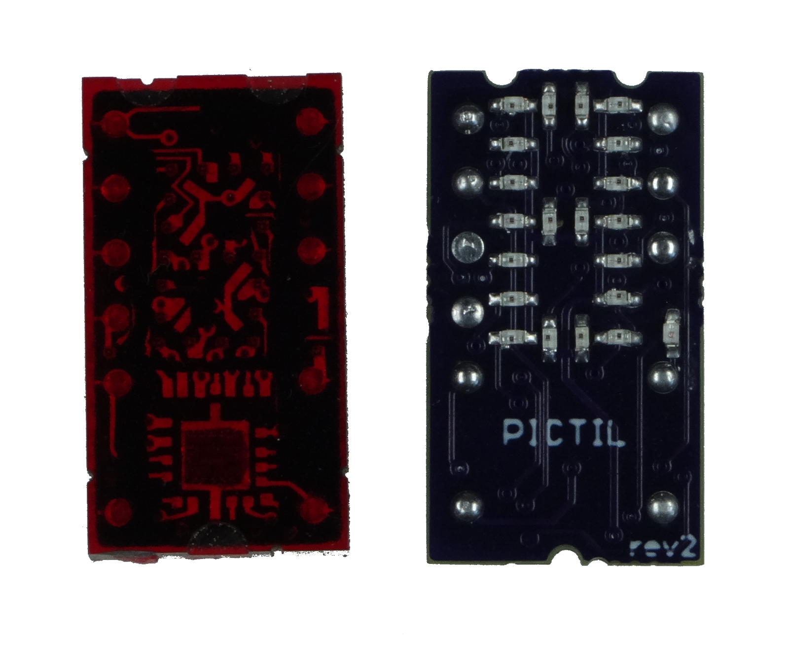
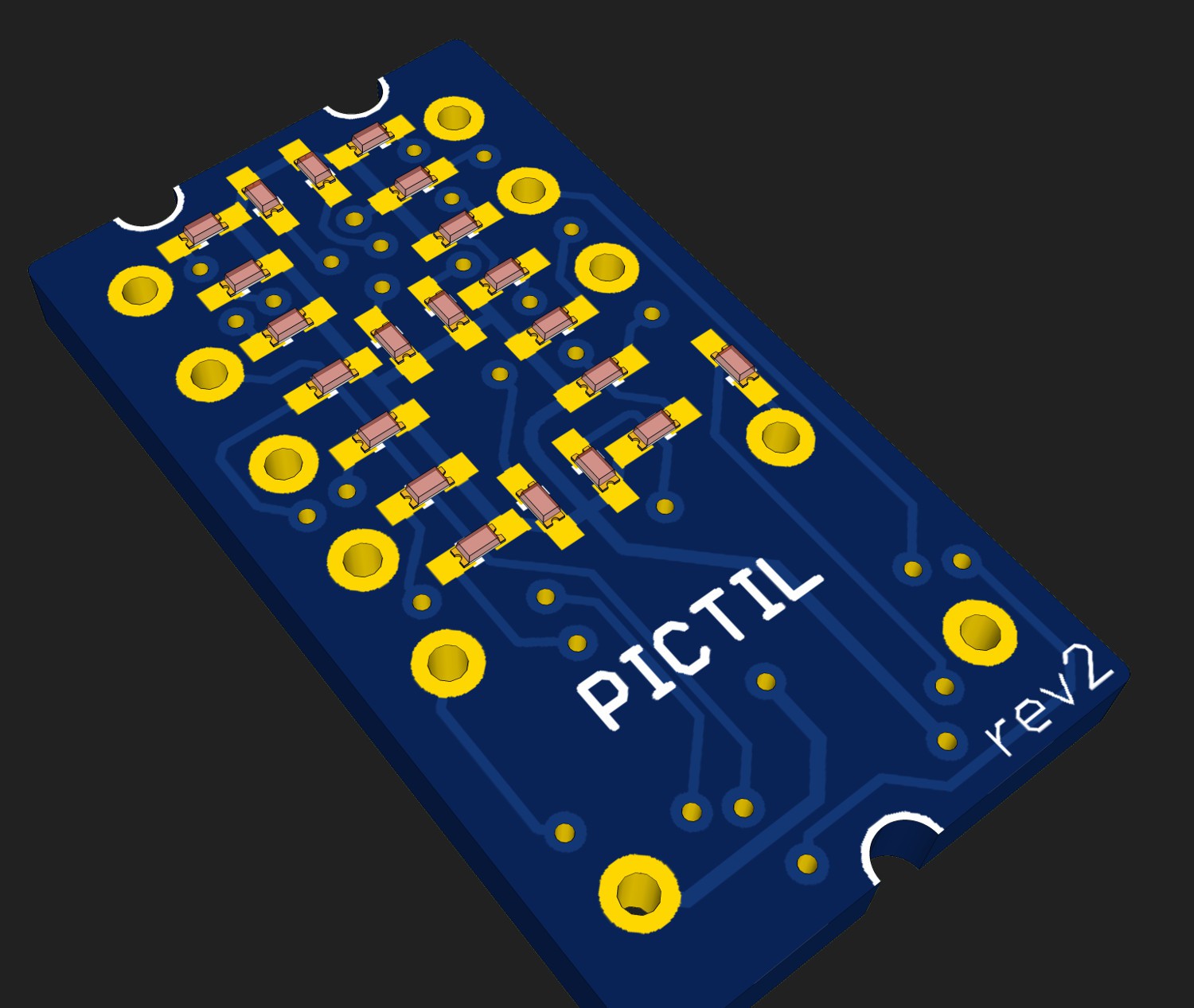
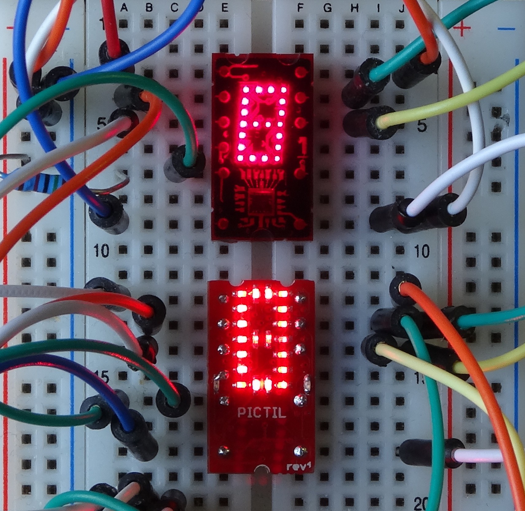
Not much to say about the Hardware. Its an quite basic schematic. The 20 (rev1 and rev2) or 13 (rev0) LEDs are controlled by the PIC. There are four inputs for the value and one latch input. The blank input is built discrete with a p-channel mosfet.
You can find schematic down in the file section.
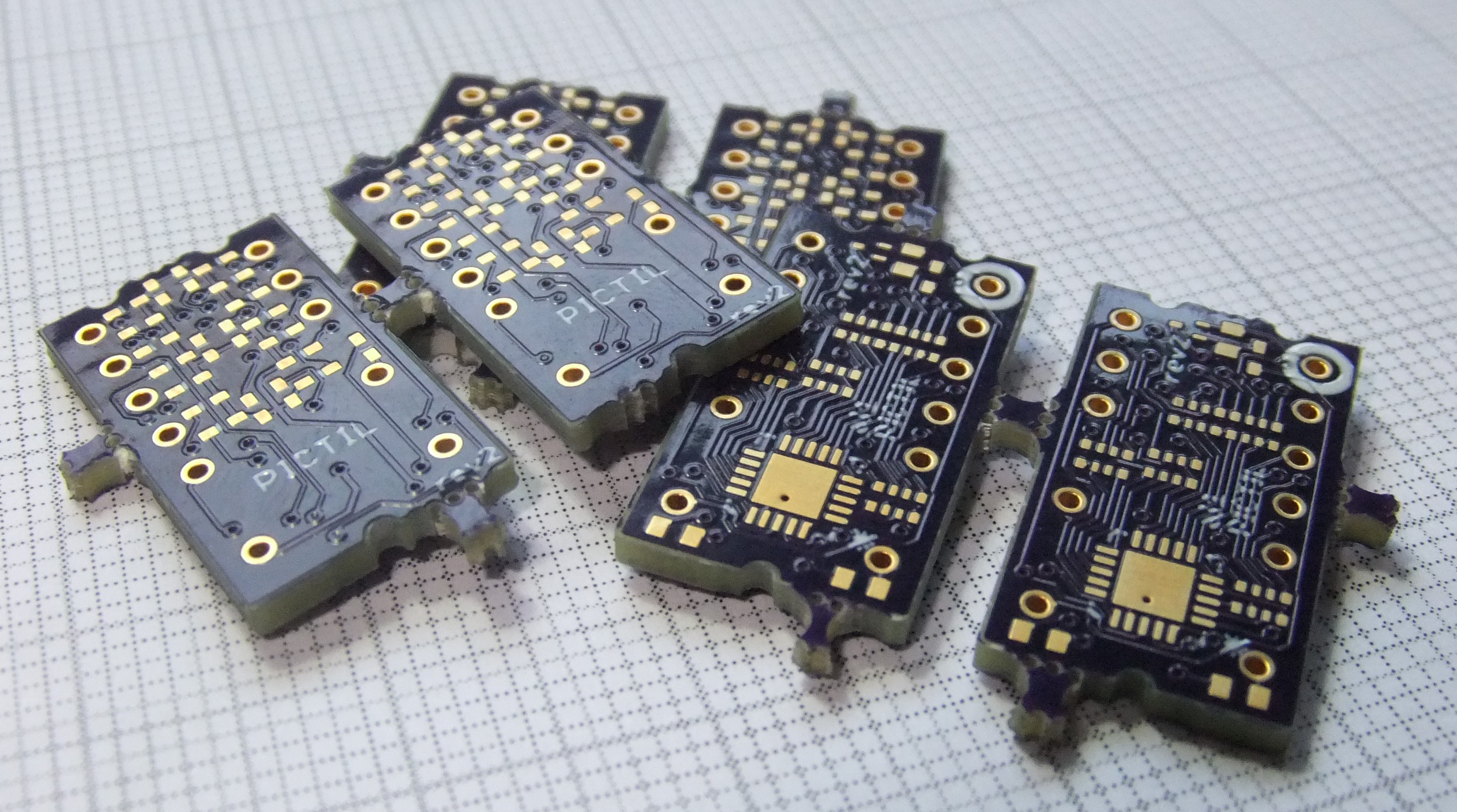
There are different Hardware revisions available. Only rev2 and rev1NEO boards are working completely (see Errata). Following some additibnal information about the two working versions:
rev1NEO
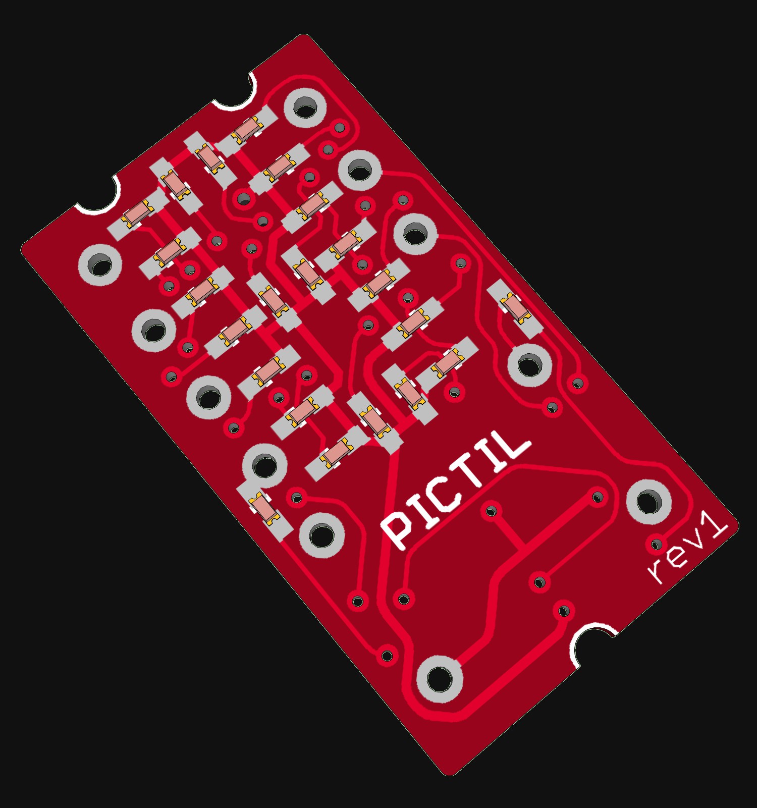
This is a correct version of rev1. It uses the now working blank circuit of rev2. The benefit of this version compared to rev2 is that also the left dot is available. This dot is not present in rev2. The downside of this revision is that is uses to small traces to fulfil OSH parks design rules. 5mil traces/space and 12mil min Vias are used. This is manufacturable by dirtypcbs for example.
rev2
This Hardware Version does not have the right dot. Only the left dot
is available. That is because rev2 conforms OSH Parks design rules (6
mil traces/space 13mil min Via),
Software
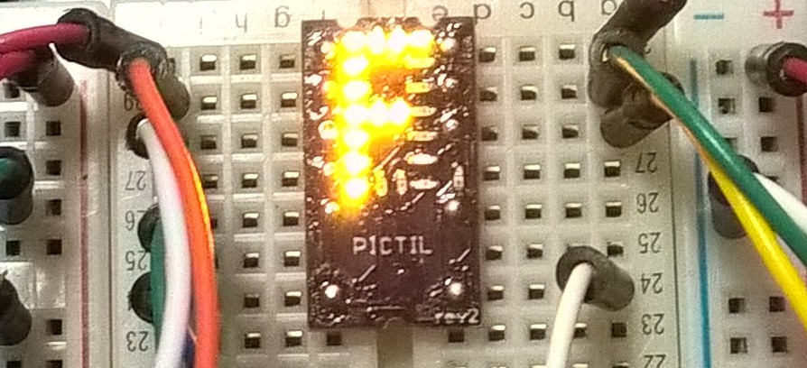
The software is nothing special yet. After some setup there is a endless loop. In this loop the led status gets updated if the input status changed and if the latch pin is low. The fonts for the LEDs is stored in a array. You can find the c-code as well as ta compiled hex-file in the bitbucket repository.
Future
- Update and Improve the software
- going in sleep mode if latch in high (saving energy)
- interrupt on falling edges of RA3/latch to react faster and more like original TIL311
- optional alternative control scheme (serial? /i2c? )
- Get alternative software for other use cases
- pulse counter
- bus-controlled Display
- #tiny7 replacement software
- clock / timer /counter / thermometer....
- Sell / Shop / Tindie
- Some already did ask about that. I am thinking to sell some ( or at least PCBs).
- Or maybe crowdfunding? mh? would be a good case to test that.
- Crazy Idea in my mind
- RGB version
- Version with Bluetooth or other radio
- Programming/Testing jig
Errata
rev0
There is I mistake in the schematic and because of that also on the circuit board. I should had noticed that before but source and drain are interchanged. This can be fixed by not using the blank-circuit and bridging the transistor by a 0 Ohm resistor. See also this log.
rev1
The error is still there. Thought I did fixed it. (see rev1NEO for a fixed rev1)
rev1NEO
No known (yet)
rev2
No known (yet)


 Philip
 C. Scott Ananian
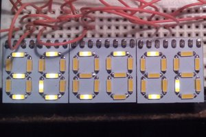
 Yann Guidon / YGDES
 deʃhipu
try the attiny3226 in 3mmX3mm vqfn, no?