Close
0%
0%

Arduino RF Controlled Robot

Arduino RF Controlled Robot

Public Chat
Similar projects worth following
What sup guys!!! Today we will make an Arduino controlled robot. It is somewhat similar to my previous project. The only difference is that instead of using a gyroscope sensor I used a Joystick module. The robot is controlled wirelessly using the Rf (ASK) transmitter and receiver module. Both the circuits consist of two Arduino Boards and both are powered using 9 V batteries.

Working -

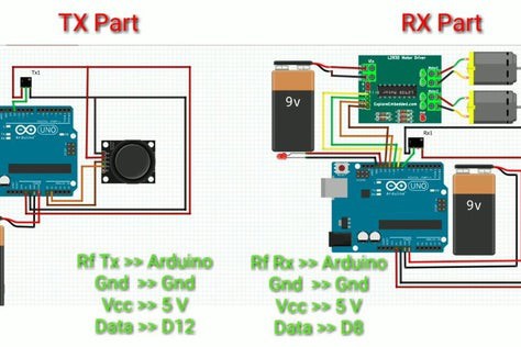
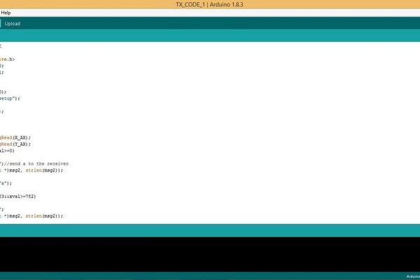
The working of this project is quite straight forward. The Joystick module gives analog values for the X and Y axis movement. This values are then compared with the set values by the help of various if else statements. And according to that a character is sent to the receiver. Like in this case a character 'a' is sent for forward movement of the robot.

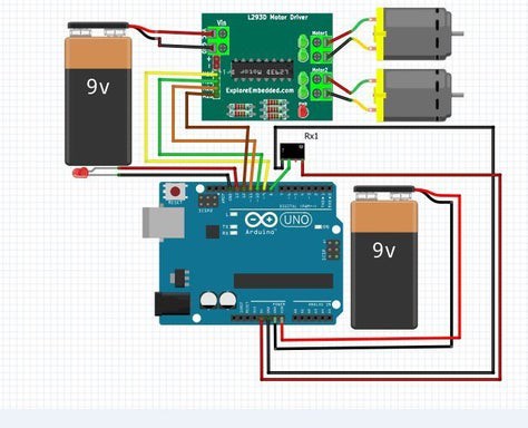
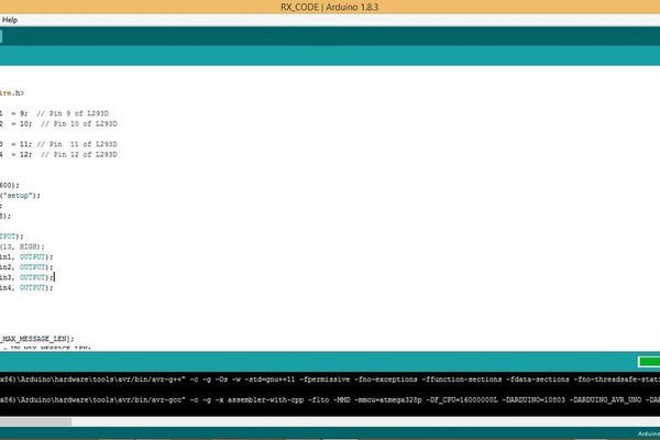
These characters are then received by the Rf receiver at the other end. The receiver's job is to just receive the character and send it to the Arduino. The Arduino then moves the robot according to the sent character. The movement is controlled by the L293d Motor driver module. This is the basic working of the project. Now let's head on to build this robot.

ino - 1003.00 bytes - 02/11/2020 at 19:27

Download

ino - 2.15 kB - 02/11/2020 at 19:26

Download

  • 2 × Arduino Uno Board
  • 1 × Joystick Module
  • 1 × Rf transmitter and receiver module
  • 1 × Motordriver Module (L293D)
  • 2 × Breadboard Electronic Components / Misc. Electronic Components

View all 9 components

  • 1
    Get the Supplies!!!

    Buying supplies is a crucial part for any project. And most importantly at right prices. And for that I recommend you to buy them from UTSource.net website. They provide good quality components at low cost and fast shipping. They also provide high quality PCB's for manufacturers and prototypers. Do check them out now and avail their free one month Plus membership trial which gives a lot of benefits to customers.

  • 2
    Circuit Diagram

    The circuit diagram for this project is quite simple. And it takes about only 10 minutes to build this project. The connections are shown in the circuit diagram above. The joystick module is connected to two analog inputs and the transmitter is connected to a digital pin. Here I used pin 12. You can use the serial port but that will cause problems while uploading the sketch. So instead use the Virtual wire library and make some other pin a tx pin.

    The receiver part consists of the motor driver module and the RF receiver. Again here we used the Virtual wire library. A led is connected to get the status if a charater is received or not. Both of the boards are powered using 9 V batteries. And one separate battery is used to power the motor driver module.

  • 3
    Upload the Sketch

    Now let's upload the sketches to the Arduino Boards. You can get the sketch from below.

    // TRANSMITTER CODE

    #include <VirtualWire.h>
    const int X_AX = A0;
    const int Y_AX = A1;
    void setup()
    {  Serial.begin(9600);      Serial.println("setup");  vw_setup(2000);   vw_set_tx_pin(12); }
    void loop()
    {  int xval = analogRead(X_AX);  int yval = analogRead(Y_AX);  if(xval<=261&&xval>=0)  {   char *msg2 = "a";//send a to the receiver   vw_send((uint8_t *)msg2, strlen(msg2));   vw_wait_tx();   Serial.println("a");  }  else if(xval<=1023&&xval>=782)  {   char *msg2 = "b";   vw_send((uint8_t *)msg2, strlen(msg2));   vw_wait_tx();   Serial.println("b");  }  else if(yval<=261&&yval>=0)  {   char *msg2 = "c";   vw_send((uint8_t *)msg2, strlen(msg2));   vw_wait_tx();    Serial.println("c");  }  else if(yval<=1023&&yval>=782)  {   char *msg2 = "d";   vw_send((uint8_t *)msg2, strlen(msg2));   vw_wait_tx();    Serial.println("d");  }  else   {   char *msg2 = "e";   vw_send((uint8_t *)msg2, strlen(msg2));   vw_wait_tx();    Serial.println("e");  }
    }

    // RECIEVER CODE

    #include <VirtualWire.h>//Motor A right
    const int motorPin1  = 9;  // Pin 9 of L293D
    const int motorPin2  = 10;  // Pin 10 of L293D
    //Motor B left
    const int motorPin3  = 11; // Pin  11 of L293D
    const int motorPin4  = 12;  // Pin 12 of L293D
    void setup()
    {    Serial.begin(9600);     Serial.println("setup");    vw_setup(2000);      vw_set_rx_pin(8);        vw_rx_start();          pinMode(13, OUTPUT);    //digitalWrite(13, HIGH);    pinMode(motorPin1, OUTPUT);     pinMode(motorPin2, OUTPUT);    pinMode(motorPin3, OUTPUT);    pinMode(motorPin4, OUTPUT);
    }if (vw_get_message(buf, &buflen))     {  int i;  for (i = 0; i < buflen; i++)  {     if(buf[i] == 'a')//if button a is pressed.... i.e.forward buton      {        digitalWrite(13, HIGH);        Serial.println("Forward");        digitalWrite(motorPin1, LOW);        digitalWrite(motorPin2, HIGH);//FORWARD        digitalWrite(motorPin3, LOW );        digitalWrite(motorPin4, HIGH);      }     if(buf[i] == 'b')      {        digitalWrite(13, HIGH);        Serial.println("Backward");        digitalWrite(motorPin1, HIGH);        digitalWrite(motorPin2, LOW);//REVERSE        digitalWrite(motorPin3, HIGH);        digitalWrite(motorPin4, LOW);      }      if(buf[i] == 'c')      {        digitalWrite(13, HIGH);        Serial.println("Left");        digitalWrite(motorPin1, LOW);        digitalWrite(motorPin2, LOW);//LEFT        digitalWrite(motorPin3, LOW);        digitalWrite(motorPin4, HIGH);      }     if(buf[i] == 'd')      {        digitalWrite(13, HIGH);        Serial.println("Right");        digitalWrite(motorPin1, LOW);        digitalWrite(motorPin2, HIGH);//RIGHT        digitalWrite(motorPin3, LOW);        digitalWrite(motorPin4, LOW);      }     if(buf[i] == 'e')      {        digitalWrite(13, LOW);        Serial.println("Stop");        digitalWrite(motorPin1, LOW);        digitalWrite(motorPin2, LOW);//STOP        digitalWrite(motorPin3, LOW);        digitalWrite(motorPin4, LOW);      }      Serial.print(" ");  }  Serial.println("");
    }
    }

    Once you upload the code connect the batteries and give your project a run. If the robot moves in the opposite direction of the joystick then just swap the motor wires. 

View all 4 instructions

Enjoy this project?

Share

Discussions

Similar Projects

Does this project spark your interest?

Become a member to follow this project and never miss any updates