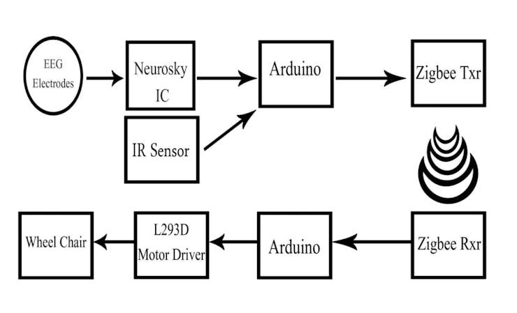
• 1
    Step 1

    Story

    It is very clear that EEG sensors and headsets are becoming more commercialized and thus accessible to users for building custom brain-machine interfaces with various functionalities from switching TV channels to controlling wheelchairs as in this case. We decided to take it one step further. Here we will show you how we created a Mind-Controlled Robot using Arduino which was later converted to a wheelchair.


    About our Sponsor

    This Project is Sponsored by WIN SOURCE. WIN SOURCE is a leading electronic components supplier from China.


    NeuroSky produces and supplies an IC that can provide filtered, raw EEG data from electrodes connected to our head. But they also produce awesome hardware equipment for toys such as MindFlex (a game in which a ball is mind-controlled using the focus and relaxation level of our mind). For us, this was a cheaper option to get the EEG data for our project. It could give us everything, neat and filtered for less than half the cost.

    Components Required

    Hardware list:

    • Mind Flex • AAA batteries for the headset • Arduino • Some hookup wire. • A PC • L293D Motor Driver IC • DC motor Driver Board • DC motor Power Supply

    Software list:

    • Arduino Brain Library • Processing Brain Visualizer • Processing GUI

    MindFlex

    Mindflex is actually a game from Mattel which uses our brain frequency to move a ball through obstacles. The brain waves (EEG Signals) are captured using electrodes that are placed in the headband and these waves are processed to get the attention and meditation level, which is later fed to the base station via Bluetooth and uses it to control the fans and the movement of the ball.

    We could modify the circuit in such a way that instead of transmitting the raw signals into the base station, we grabbed the signal directly form Neurosky EEG Chip, before being transmitted using an arduino micro controller leaving a schematic that looks more like this

    We could process these raw signals using an arduino library and extract the value of meditation and attention from the signals. These signals are then used for moving the robot/wheelchair.

    Click here to know how we modified Mindflex gaming headset to extract what we needed.

    Eye Blink switch

    This Eye Blink sensor is IR based. Since the sensor works by looking for reflected light, it is possible to have a sensor that can return the value of the reflected light. This type of sensor can then be used to measure how “bright” the object is.This is useful for tasks like line tracking. The variation of brightness across the eye will vary as per eye blink. If the eye is closed means the output is high otherwise output is low. This to know the eye is closing or opening position. This output is give to the microcontroller.

    TCRT5000 sensor consist of an IR diode that constantly fires IR rays and and the output stays low until the power of the reflected IR wave is above the threshold value. Here, the infrared sensor is used to switch between straight movements and sidewise movements. It is fixed in a spectacle and it is placed in front if eye. The blinking of eye for a particular time is detected by the infrared sensor and hence the switching action is done. The output of the infrared sensor is given to Arduino microcontroller along with EEG input signals for further processing.

    Below is the Circuit Diagram and PCB layout of the control Board

    The Algorithm

    The values of Attention and Meditation signals can be adjusted by the patient after some practice. The attention and meditation signals can be divided into three regions as shown. The variation will be fuzzy and will vary with each patient. According to a patient’s response, the levels of these signals can be adjusted and can be used to control the wheelchair according to the following algorithm. Either attention or meditation signal value is taken. This value is used to control the wheel chair to move the chair forward, backward, right or left. The switching between straight movements and sidewise movements can be done using an infrared switch.

    The digital values of attention and meditation signal can be obtained from the Neurosky EEG chip and these values can be processed using Arduino microcontroller. The algorithm for processing is shown in the figure.

    The Robot/Wheel Chair

    Now lets get down to the moving part of Mind Controlled Robot using Arduino. Two wheels of the wheel chair are connected to the L293D motor driver. The L293D Dual H-Bridge Motor Driver Board is a great value and can be used with a variety of robot controllers. It features a powerful L293D motor driver module with a heavy duty heat sink. It is powerful enough to drive motors from 5-35 V at up to 2 A peak. This post explain everything about H Bridge and L293D and helps you get started with wheeled robots.

    Below is the Circuit Diagram and PCB layout of L293D Motor Driver Circuit

    Follow the steps below to configure the motor controller board to work as a typical robot motor driver for use with two DC motors.

    • Attach your robot’s motors to the green Motor A and Motor B screw terminals.
    • Connect the ENA and ENB to PWM capable digital outputs on your robot’s microcontroller.
    • Connect the IN1, 2, 3 and 4 pins to any digital outputs your robot’s microcontroller.
    • Apply 5-16V to the board by connecting positive (+) to the blue VMS screw terminal and ground (-) to the blue GND screw terminal.
    • See herefor details on controlling the motors with your robot’s microcontroller.

    Get Complete Code and instructions for Mind Controlled Robot.

    Wireless Version of Mind Controlled Robot using Arduino and Bluetooth Module

    The same can be made wireless by intercepting the bluetooth signal by employing a HC12 Bluetooth module or incorporating a ZigBee in Transmitter and Receiver Units.

    Full tutorial for wireless version of the Mind Controlled Robot using Arduino will be posted soon.