Jeff Cooper
-
First Log: Inspiration
02/16/2020 at 00:11 • 0 commentsThe project is still very much in the design phase, and I can't publish any code yet until I've gone through the copyright release process with my employer (this is a purely personal project, and is not associated in any way with my employer).
This project took inspiration from these projects:
Motivation
I've never wanted a smartwatch, because I never really saw the value proposition. I've worn a Casio G-Shock since I was 11. It's durable, solar-powered, and atomic-set. I'm only on my second one because the first one's rubberized casing started to fail; the watch itself was fine.
Nevertheless, that hasn't stopped me from wanting to design and build one. I consider myself a proficient programmer and competent at designing simple PCBs, but I've never done anything that required low power consumption, nor anything that needed to fit in a space as small as a wristwatch, nor anything with a battery. So this should be fun.
Inspiration
I'm basing this project around a few different points of inspiration. In addition to the two projects linked above, I've been recently fascinated by the power consumption numbers of Sharp Memory LCDs. A display that's always-on and requires tens of microamps to sustain yet requires no complex driver circuitry seems like the perfect blend between e-ink and LCD technology.
Then I came across the nRF52840, which claims a 1.5uA sleep current with RTC wakeups and RAM retention enabled, and an average of ~30uA in BLE advertising mode. I'm sure this is neither the lowest consumption available nor the first to promise these numbers, but coming from the world of the ESP8266 / ESP32, this was staggering. Combined with Memory LCD, it suddenly seemed like wrist-mounted technology was within reach. After all, a 500mAh battery will fit comfortably in a device the size of a typical smartwatch. Even if I assume 500uA average power draw for the system, that's 41 days of life.
This got me thinking. If I had a completely programmable, BLE-enabled device on my wrist at all times, what would I do? If I paired it with my phone, suddenly that BLE radio can call webhooks into my home automation system. I could pair it with my laptop using an HID profile, and use it as a remote when giving presentations. And I've always believed that watches should have flashlights in them; now I finally had a chance to make that happen.
-
Memory LCD
02/16/2020 at 00:48 • 3 commentsChronio, the amazing project from which I've drawn a lot of inspiration, is the first place I saw a Memory LCD. The model used in that project is no longer produced, but a similar one, the 1.28" LS013B7DH03, is readily available. So I bought one, and realized three things right away
- 1.28" diagonal is crazy small. I wanted something bigger, and fitting all the circuitry I wanted on an appropriately-sized PCB was going to be tricky.
- I definitely wanted to include a light of some kind in my design.
- Generating a 60Hz signal, which is required by the display to prevent burn-in, is going to be a bit of a pain.
Size
The next biggest memory LCD available from Sharp is the LS027B7DH01A, which is 2.7" diagonal. I figured this was just too big for a smartwatch, so I was frustrated. Until I stumbled on something fortuitous:
Lighting, a pleasant surprise, and a baffling discovery
When reading about lighting options for memory LCDs, I came across Flex Lighting, who manufacture an ultra-thin frontlight that laminates on to memory LCDs. The product looked promising, but I couldn't find any way to buy the light membrane by itself; everywhere seemed to only sell the lights pre-attached to a display. However, in the process of looking, I discovered the FlexLighting 12616, a 1.8" diagonal Memory LCD with a light attached. It seemed perfect, so I dug deeper. Like their other products, the 12616 is based on a Sharp Memory LCD. This one is based on the LS018B7DH02, a product which exists nowhere in Sharp's catalog, and can't be purchased anywhere except as part of the 12616. The only reference I could find from Sharp to this device is from their 2018 LCD product catalog (PDF Warning), which lists it as "under development."
Let's just guess
Aside from RF (which, speaking as the holder of an extra-class ham radio license, is dark sorcery incomprehensible to mere mortals), I didn't think there was much in electronics development that was more frustrating than trying to find information in a poorly-written manufacturer's datasheet. It turns out I found something: trying to find information without any manufacturer's datasheet.
I'm reasonably comfortable guessing the communications protocol. Every other memory LCD from Sharp has the same unidirectional (write-only) SPI interface on a 10-pin, 0.5mm pitch FFC connector. However, there are two distinct groups of memory LCDs that I've been able to determine: ones that require 5V power and a 1Hz biasing signal on the EXTCOMIN pin, and ones that require 3.3V power and a 60Hz biasing signal on EXTCOMIN. Everything smaller than the 1.8" display is in the 3.3V class, and everything larger is in the 5V class. I'll be able to experiment when I get my display in a few days, but until then I'm a bit stuck: the schematic is done and the PCB is routed... unless I need to go back and add in a 5V regulator in addition to the 3.3V one.
I suspect (and hope, desperately) that the display will be 3.3V, since 1.8" is closer to 1.28" than 2.7", but I won't know for sure until I can try it.
60Hz, or maybe 1Hz
The 1.28" screen I've been playing with requires a 60Hz signal on EXTCOMIN. The nRF52840 runs FreeRTOS and supports multiple tasks. The signal can be +/- a few Hertz, so setting a 16ms timer and toggling a digital pin every time it goes off should solve the problem, right?
Well yes, but also no: setting this timer raises the apparent power consumption on my dev board from ~60uA to ~500uA. (Note: I'm using the Sparkfun Dev Board with the power LED desoldered. The power LED draws 6mA!). This is measured on a digital multimeter, so it's possible that those 500uA spikes are short and the multimeter's measurement techniques cause it to display the peak rather than the average. But it's also possible that I'm actually averaging 500uA.
My current plan is to use the square wave output on the M41T62Q RTC module. I had originally chosen this particular RTC over the more popular DS1302 for space-saving reasons: the DS1302 is only available in the SOIC-8 package, whereas the M41T62Q is available in a 3mmx3m QFN-16 package -- It turns out that on a board that's only about 35mmx25mm, SOIC-8 is HUGE. The M41T62Q has two big advantages: first, it has a configurable square wave output that can range from 1Hz to 32.768 kHz (in multiples of 2). This means that I could drive either 1Hz or 64Hz, depending on what the LCD requires. Second, its operating current is only 35uA, with a 350nA timekeeping (sleep) current. Even if I assume a constant 35uA current, that's way better than the ~400uA current spike caused by waking up the nrf52840. I also wired this square wave output to a GPIO pin on the MCU, though I'm not totally sure if that's going to be useful yet.
-
A 1.8" Disappointment
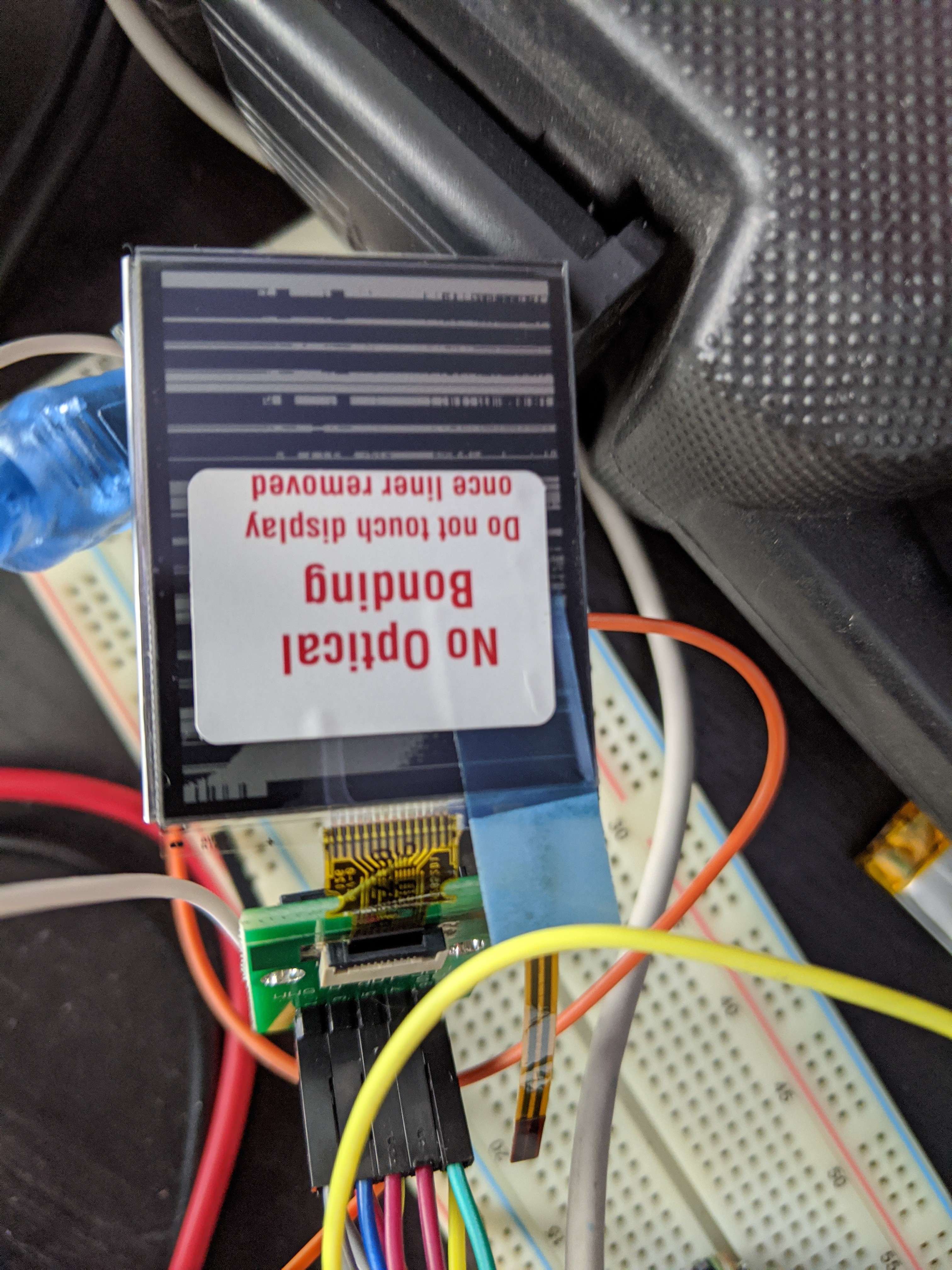
02/17/2020 at 19:48 • 0 commentsMy mysterious perfect-sized LCD came today. I immediately noticed one problem, then later noticed a second. Both are visible in one picture:
![]()
- "No Optical Bonding". This LCD does not have a protective front layer. I guess the flexible frontlight takes the place of the standard glass. This is solveable; I could get a protective film layer to put over it, but the second problem is more severe:
- The display is broken. Without a datasheet, I have to assume that the display uses the same protocol as the others in Sharp's line (side note: JDI, the other manufacturer of memory LCDs, seems to use the same protocol for their monochrome memory LCDs). Assuming that the data I'm sending it is correct, it appears that the display itself is damaged somehow. On the plus side, it powers up fine on 3.3V (I did also try it with a 5v supply. This didn't hurt the display, but also didn't change its behavior).
So I'm back to square one on the display front... probably back to a 1.28" square one, since 2.7" is far too big.
Some other notes about the display:
- The external dimensions, excluding the FFC connector, are about 41.43mm x 31.88m
- The frontlight looks great.
-
In-Progress Renders
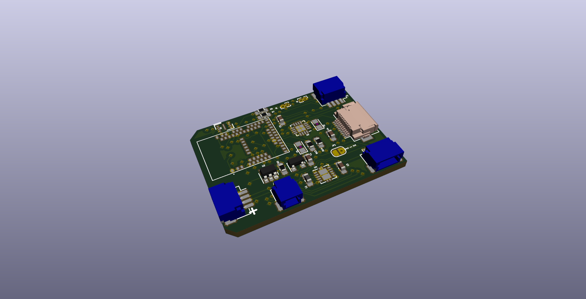
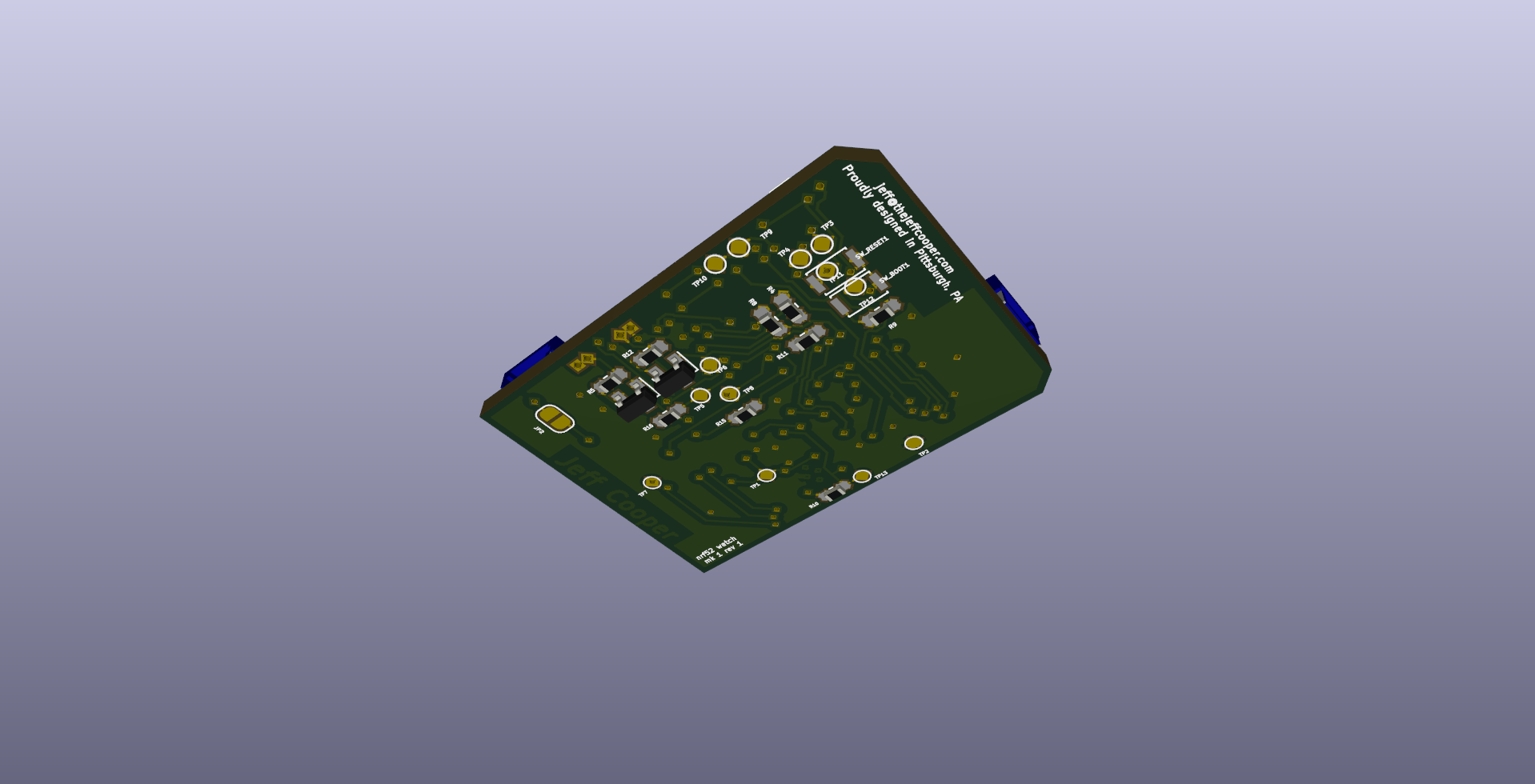
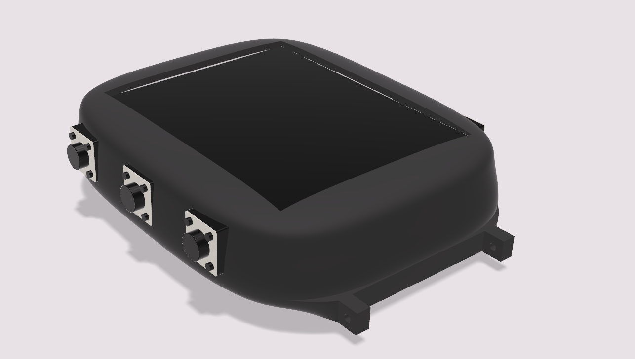
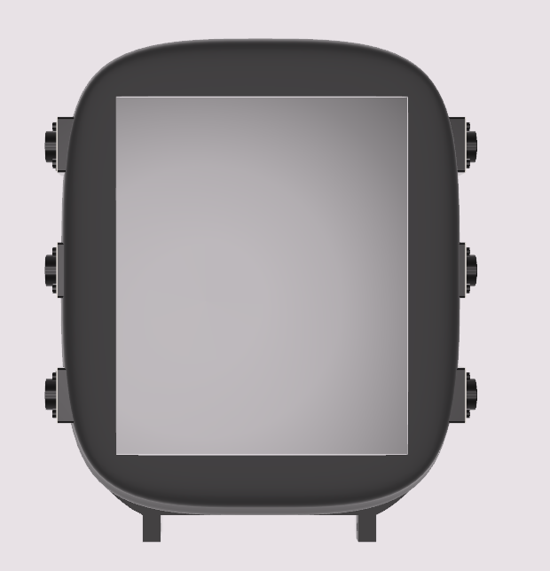
02/18/2020 at 04:46 • 0 commentsEverything is still a work in progress, and some things I haven't even started attempting. But the PCB is mostly done (I may have to go back and add a 5v boost converter after all), and the case is starting to take shape. Here are some renders so far, because every project needs aspirational renders.
The side buttons are definitely placeholders. They might make it to the first prototype, since those 6mm SMD buttons are super common, but eventually I'll probably CAD up some custom buttons that recess into the case, and put in some low-profile buttons on the PCB.
The buttons connect on identical daughterboards with JST-SH 4 pin connectors (the blue connectors on the right side of the first screenshot). By default, each pinout is 3GPIOs and one ground, but I included a jumper for each that connects one of the GPIOs to 3v3. I strategically chose this layout such that, with the jumper connected, the connector becomes a Qwiic-style connector (I'm not sure I meet the official criteria on that page to be "qwiic-compatible," so let's say it's "qwiic interoperable" -- the pinout is the same). This will let me replace one of the button panels with an I2C board. Unfortunately, I can only use one or the other; the nrf52840 only supports two hardware I2C peripherals, and one is currently being used for the RTC module. I'm relatively certain that the right side will remain with the simple 3-gpios-and-a-ground layout, though. Since I wear my watch on my right hand, this is the side that faces in towards my body. I hope to replace the left side (facing out) with something a little fancier, potentially including a flashlight and/or laser pointer. These would require an I2C IO Expander or driver IC, simply because the GPIOs on the nrf52840 can't source enough current for an effective flashlight. By providing a connection straight to 3v3, I can access the full 250mA of the regulator. Will this be enough for a flashlight? That remains to be seen.
The smaller connector near the bottom of the screenshot is the battery connector. This is also a JST-SH connector at the moment, but I may upgrade it to a more standard JST-PH (which is the connector that comes on every LiPo battery) now that I have the space.
I saved that space with the final JST-SH connector, on the left side of the screenshot. This will go to a small USB-C breakout (which is designed and routed, but not included in this post) that I can mount wherever in the case is most convenient, without having to worry about the orientation of the main board (which is already constrained by the short FFC connector on the LCD). The four pins are VBUS, D+, D-, and GND. Since I'm using USB2.0 compatibility mode, the 5.1k resistors between the CC pins and GND are on the breakout. The connections between the two pairs of positive and negative pins on the connector are also handled on the breakout, which saved complexity on the main board. I'm a little worried about the RFI I might get from running USB over wires that can flop around in the case -- they should be 10mm or less, but it's a high-speed signal. If I have issues, I might have to rethink this, but I'm not too worried.
I also got an email back from some helpful people at FLExLighting with some information about the LCD that I got, and a STEP file for the module that I bought. They informed me that the display itself is meant to be run at 5v power, and promised to send a datasheet soon. I sent them picture of my screen, which I'm more convinced than ever is actually broken and not just misconfigured somehow. I'll post an update once I have something more concrete on the display front.
![]()
![]()
-
Datasheet!
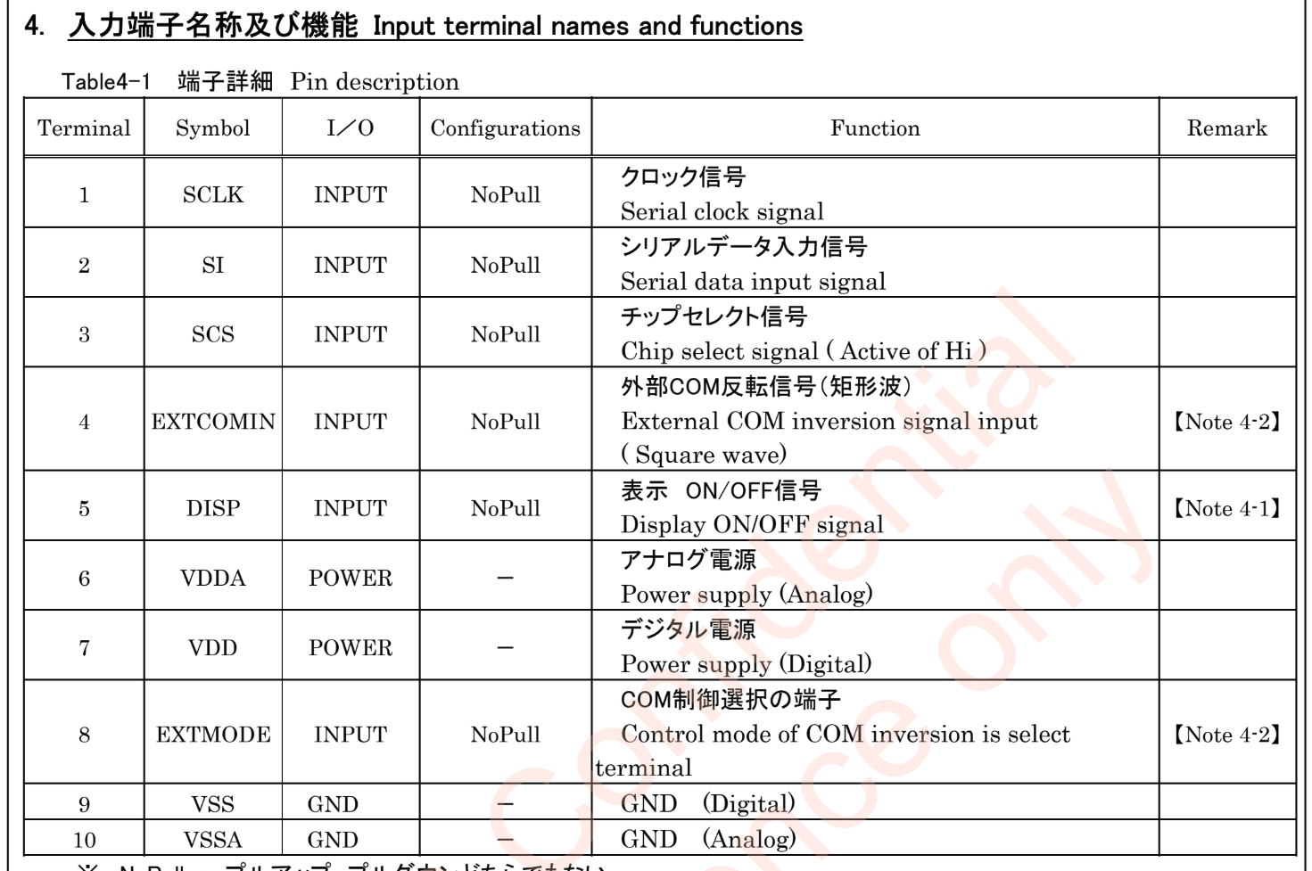
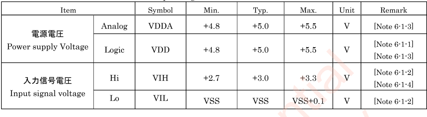
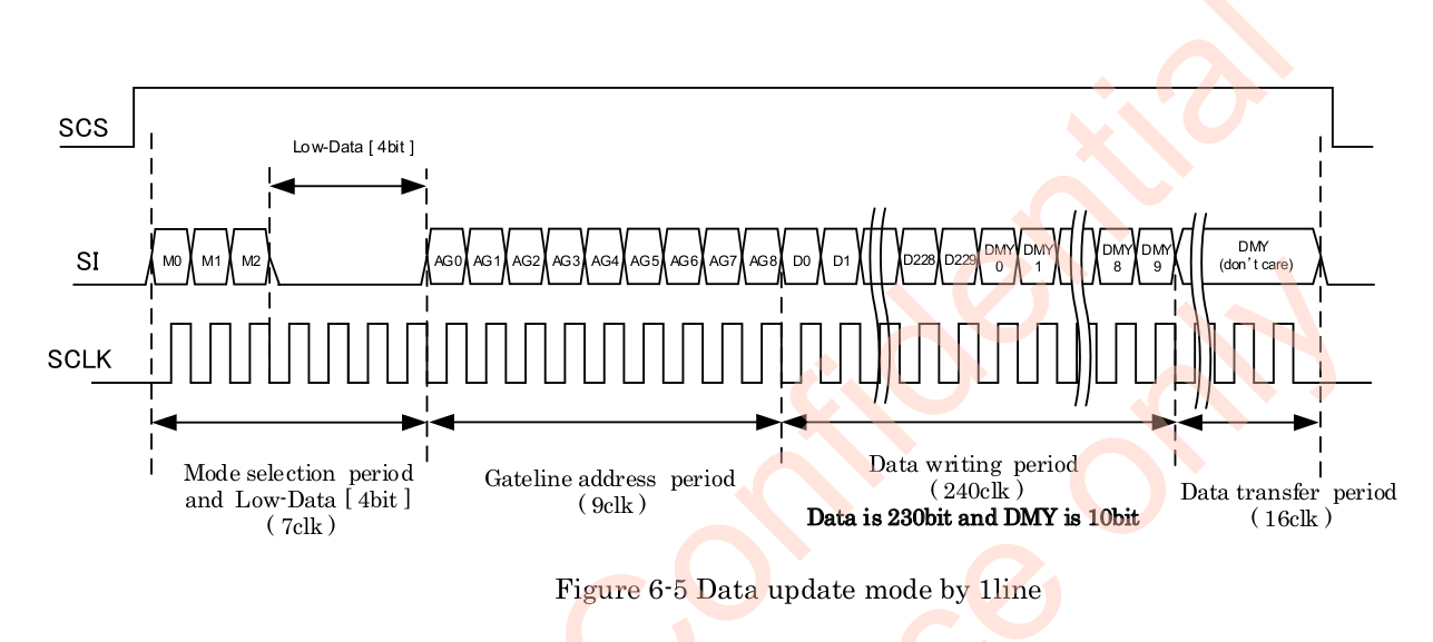
02/19/2020 at 07:18 • 3 commentsOn Friday night, I emailed both FLExLight and Sharp, asking for the datasheet for the LS018B7DH02. I honestly wasn't expecting to get a response, but (as briefly mentioned in my last post), Adnan and Yulia from FLEx responded Monday evening. Tuesday morning, both they and Beth from Sharp responded with a copy of the datasheet! Half of it is in
ChineseJapanese but the important parts:![]()
![]()
![]()
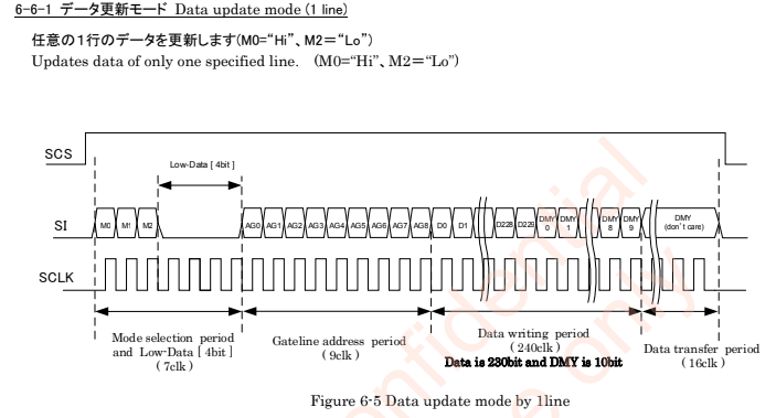
The third image is something I wouldn't have noticed if Adnan from FLEx pointed it out to me: there are 240 clocks for each line, but only 230 horizontal pixels. This means there are 10 dummy "pixels" for each line. The datasheet says that they don't matter, but that they're recommended to be zeroes.
I've ordered a replacement display, which will hopefully be here by the weekend. More updates once it's here and I can get it working.
-
LS018B7DH02 Datasheet
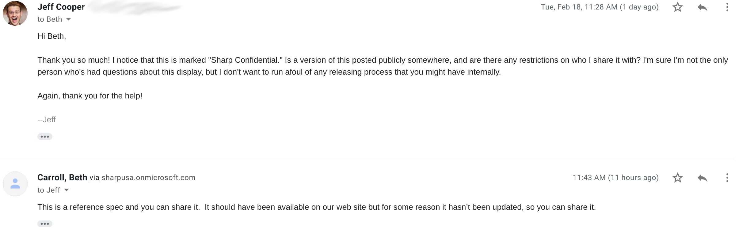
02/20/2020 at 04:46 • 0 commentsLike I mentioned in yesterday's log, the lovely folks at Sharp and FLExLight both answered my request for a LS018B7DH02 datasheet. Despite the fact that this document is watermarked with "Sharp Confidential" on every page, Beth from Sharp told me this:
Since this datasheet exists nowhere else on the internet, I'm attaching it to this project. Hopefully someone finds it helpful, since it seems like a great display!
-
The Ninth Bit and Optical Bonding
02/23/2020 at 21:01 • 0 comments![]()
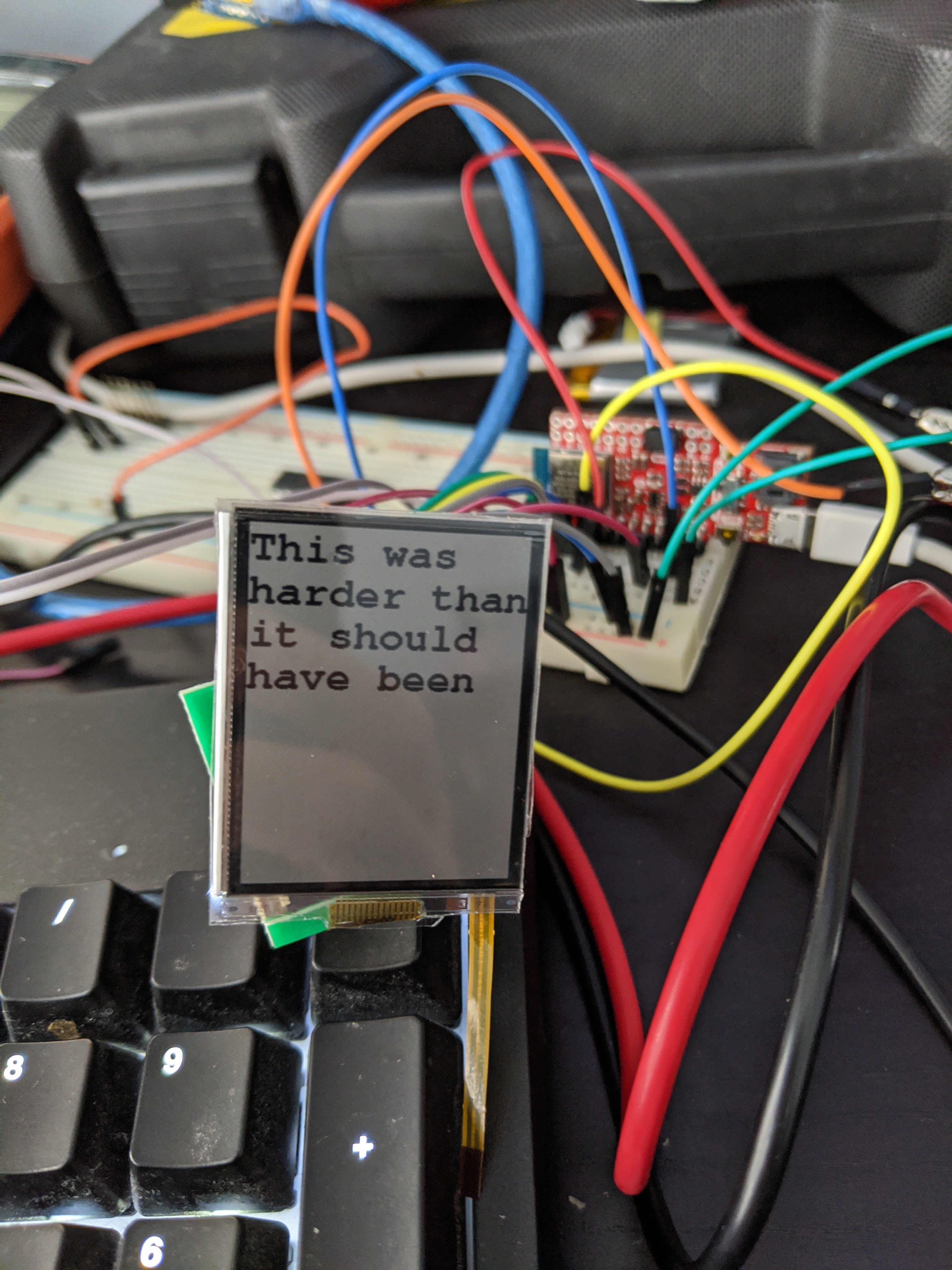
Headline first: the new display arrived on Friday, and it works! It took some wrangling, though.
With no code modifications, I was able to plug in the new display and flash it black and white. However, the "white" looked kind of gray. When I looked closer, I saw that every other line of pixels was actually black. Trying to print some text also had some funny interlacing effects, as if every other line was getting skipped, and the remaining ones were being stretched out.
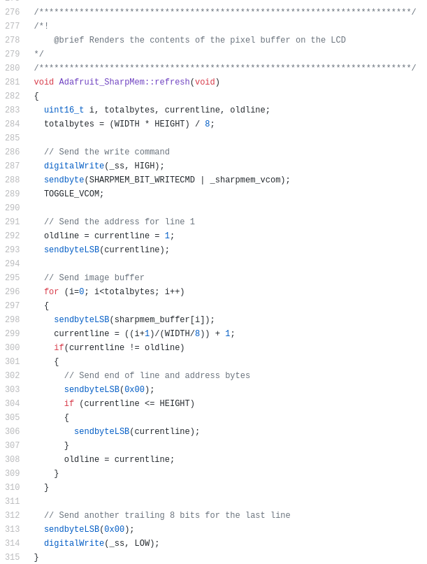
I puzzled over this for an hour or so, then decided to look closer at the datasheet versus the code. Here are the relevant sections (datasheet from Sharp, code from Adafruit). See if you can spot what might cause every other line to be skipped:
Okay, that's not obvious. Does this help?
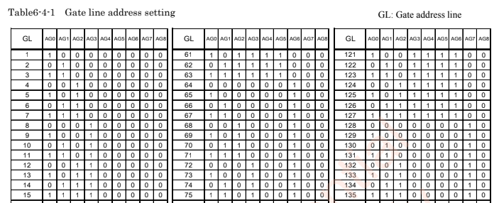
The problem, as it turns out, is that the Adafruit library was sending 8 bits of mode selection (all zeroes, line 303 in the screenshot) followed by 8 bits of line address (306). The "sendByteLSB()" method clocks a byte least-significant-bit first. But wait! The spec says that there are seven clocks of mode select (3 meaningful bits, then 4 bits of "low data") followed by nine bits of line address. This makes sense; there are 303 lines on this display, which is more than would fit in 8 bits of address. Now look at the AG0 column in the address table. The first bit that's sent is the least-significant bit of the line number, represented in binary. If we're sending an extra zero of mode select bit, that gets interpreted as AG0. Then we send the least-significant 8 bits of the line number, which effectively get shifted by one, meaning that we only send data for the even-numbered lines in the table (where AG0 = 0).
Making a local copy of the library and modifying it to send seven and nine bits rather than 8 and 8 solved the problem.
Next up, I wanted to get rid of that big "NO OPTICAL BONDING" sticker so I could actually see what I'm doing. "Optical Bonding" essentially refers to the process by which you can put a protective layer on top of a display without interfering with its optical properties. Adnan from FLEx had sent me this in our correspondence:
I, being the
lazymechanically-challenged hacker that I am, decided to ignore this advice. I had a spare adhesive plastic protector for a cell phone screen laying around, so I cut a piece to size with an xacto knife and stuck it on. After trying this on the broken display first, which digikey said I didn't need to send back, I proceeded to do it on the working one. As you can see in the photo at the top of this post, it doesn't seem to interfere with the optical properties of the display itself. Then I turned on the frontlight. In what should absolutely not have been a surprise, the manufacturer knows what they're talking about, and the light was super blotchy. Unfortunately I can't get a picture of this, since I can't find anywhere that sells a 1mm pitch, 2-position FFC connector. I was only able to power the light by holding jumper wires to the contacts on the ribbon, which required both of my hands. In my opinion, this isn't a huge deal: if I'm using the light on my watch screen, it's probably because I want to see the time in the dark, not because I need to admire the screen or read a large block of text.At this point, I think I have everything I need to order the first round of PCBs, which I have re-laid-out and re-routed five times at this point.
-
"Your package has been delivered" and other lies
02/29/2020 at 04:28 • 0 commentsA little under a week ago I ordered my parts and PCBs. That's the good news for this post.
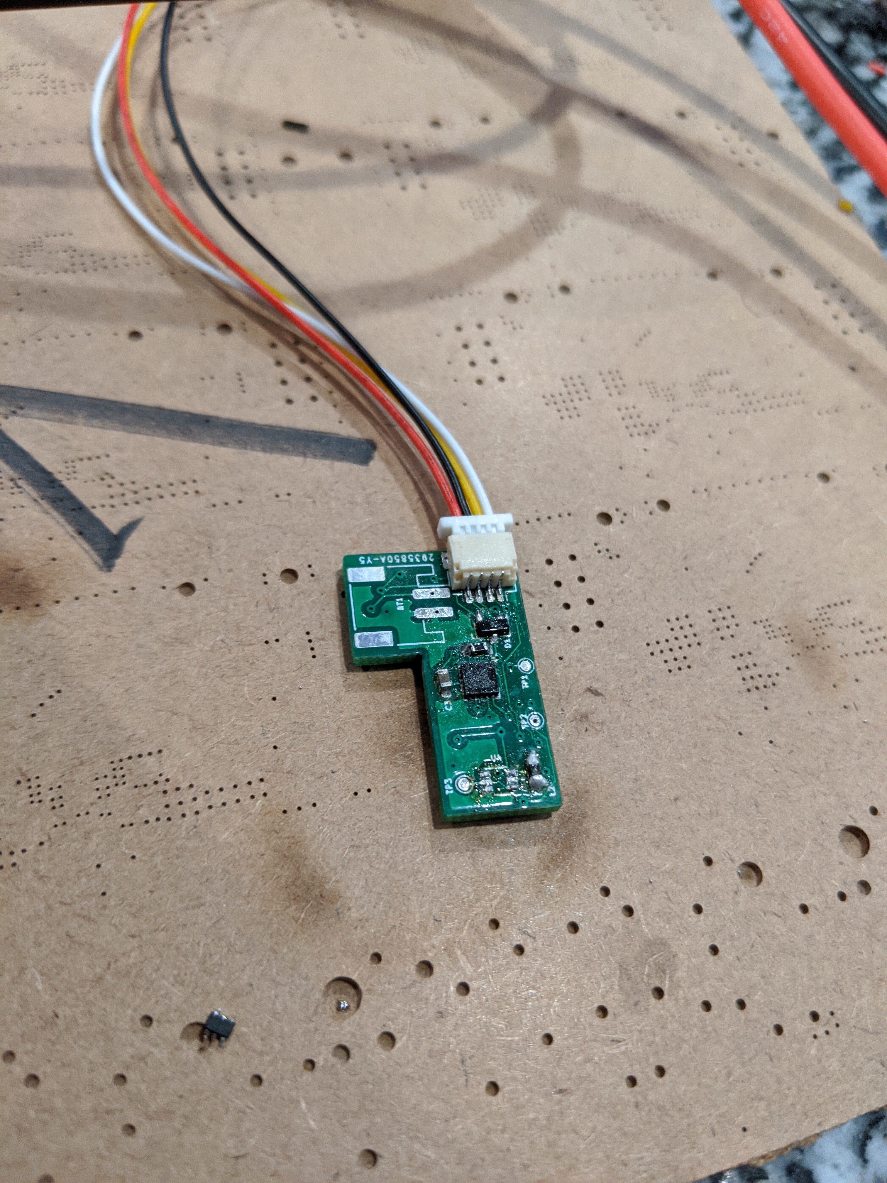
After re-laying out and re-routing my design five or six times, there are actually five PCBs that go in to this watch: a power board and a logic board connected by a 1mm-tall board-to-board connector, a USB port breakout, and two button panels that get mounted in the sides. (side boards and USB board not pictured)
![]()
After ordering the PCBs, though, I ran in to a small snag, then a much larger snag. The small snag was that JLC PCB won't v-cut any board less than 70mm x 70mm, and my board was much smaller. That was easily solvable; I split my panelized board into several smaller orders and paid a few dollars more. The bigger problem was one I didn't notice until days later, when I happened to be re-checking the previews in JLC's gerber viewer:
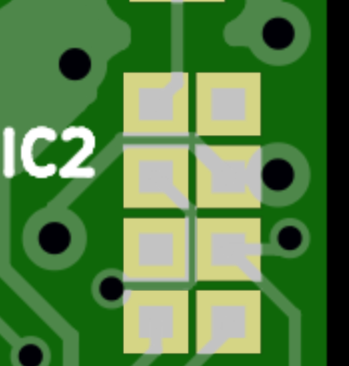
This is one example of many where neither my eyes nor my DRC rules caught unrelated traces being exposed due to overzealous soldermask exposure. Just to the right of the "IC2" text, for instance, a GND trace is partially exposed to the VCC (top left) and IRQ (below that) pins on the rtc module. I'm hoping against hope that this is a bug in the rendering, since both my local DRC and JLC's online DRC all pass without incident, but I'm guessing that this will necessitate a re-spin of the boards before I can test much of anything.
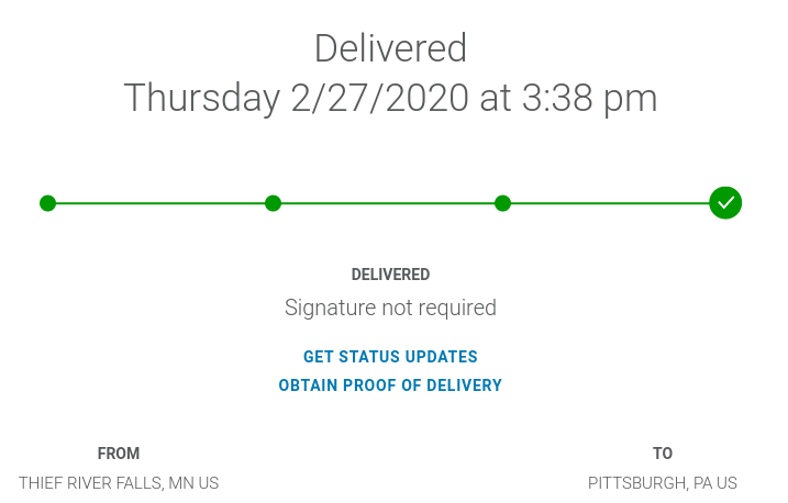
That is, if I can ever get the parts. On Thursday, FedEx notified me that my Digikey order had been delivered.
My security cameras suggested that this was a lie, since no FedEx truck or driver was at my house on Thursday. The lack of package on my step when I got home confirmed it: $200 of parts are lost in transit. I've contacted FedEx and Digikey and they're prepared to re-ship the order if it doesn't show up by early next week, but that does mean that I won't be able to do any development until then... and even then, only if the PCBs also arrive.
In the meantime, I'll focus on software and maybe a bit of enclosure prototyping. I'll also probably spend some time doing the rest of life that I've inadvertently neglected due to this project, like finishing grading my students' projects :|
-
PCBs and Magic Smoke
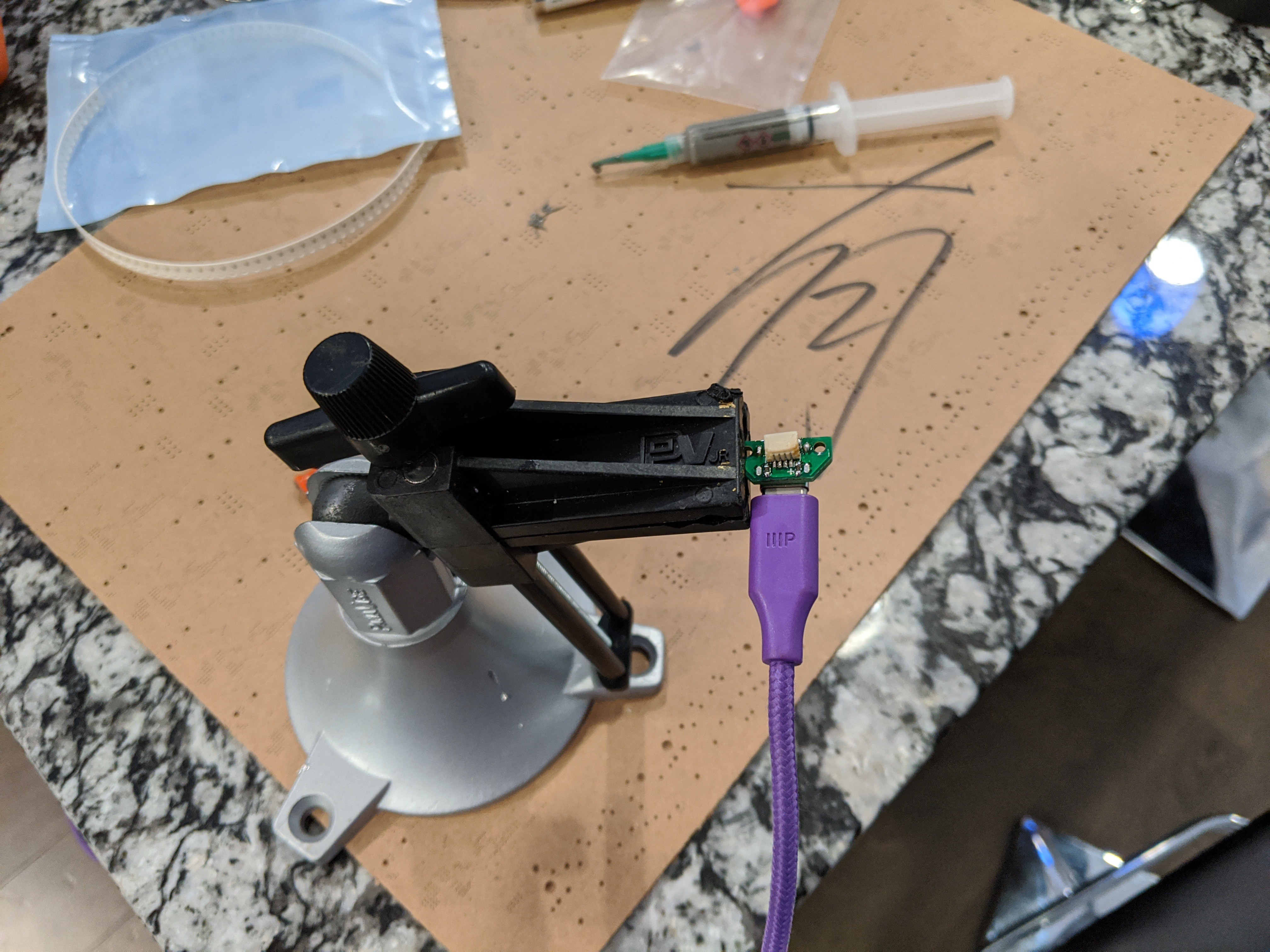
03/12/2020 at 16:42 • 0 commentsLast week, the PCBs for the project arrived, as well as the missing box of components from digikey (delivered by a friendly neighbor whom I'd never met... I don't know which house is his, but it isn't anywhere near mine). I started putting them together Thursday evening.
First up was the USB breakout board, which went swimmingly
![]()
The USB board is super simple, so I didn't really expect any issues with it. However, it was nice confirmation that sometimes, things do work on the first try. I was successfully getting 5v from a USB-C plug.Next up I moved on to the power management board, which is where I started to run into problems.
First, I discovered that I forgot to order the JST-PH battery connector and the fuel gauge IC. Neither of these was a huge deal for testing, so I soldiered on.
I put the rest of the board together, only managing to fling two battery charging ICs out of my tweezers and into the void, and, after a few quick sanity checks, did what any overly-optimistic hacker would do: I plugged it in.
![]()
The first thing I noticed was the familiar smell of magic smoke, which turned out to be coming from the battery charging IC. I quickly unplugged the board and desoldered that IC (which now had a suspicious bulge). I double-checked my schematics against the reference for those parts and couldn't find anything amiss, so I started looking for other potential causes.
This is where things got a little weird. According to my test points (which, protip, don't forget to include a test point for ground!), my +5v net was indeed getting +5v, at a slightly different voltage (if I remember correctly, a higher voltage) than the input from USB. My +3.3v net was... also getting +5v, but at yet a third slightly different voltage. I double- and triple-checked my schematic and tested the board for shorts. There was no short between any of VIN, +5V, or +3.3V, yet all of them were reading close to 5 volts. Unfortunately, around this point I ran out of time to debug and had to put the project away. I've been out of town ever since, wondering what could possibly be going on but with no way to test any hypotheses. I'm wondering if I either shorted something on the QFN 3v3 regulator (distinctly possible), or if I somehow ended up with the 5v version of that same regulator (this seems unlikely...). I'll be able to play with it more when I'm back in town next week.
In an unrelated thought, I've still been straining to think up a use case for a connected smartwatch that I would actually take advantage of. The only one I can think of is home automation control, so I've been brainstorming other ways this might be possible. If I can make a solution work with infrared or LoRA control, I can switch from the nrf52 to something like an STM32, which could potentially be even lower power. The nice thing about my design is that doing this wouldn't require a total rework of the project: the power, USB, and button boards would all be the same. Only the logic board would have to change. I may end up doing this anyways at some point, even if I keep the nrf52.
-
Coming Back
05/02/2020 at 20:32 • 0 commentsMy last update was a month and a half ago. I went on a week-long roadtrip, and when I got back, most of the USA had locked down due to COVID-19. My home hackerspace got converted into a home office, and work on this project basically stopped for a while.
I'm hoping to come back to it, though likely slowly, over the next few weeks, and start to make good progress again over the summer.
Luckily, I did hear back from my employer, who agreed to release the copyright to this project. That means that it's now easy for me to share the code and CAD with you all! I uploaded my repo (which is, at present, a bit of a mess) here.