Close
0%
0%

COSV - Cam Open Source Ventilator

Roller cam based portable BVM ventilator.

Similar projects worth following
COVID-19 sucks. Ventilators are needed.
This is our take for turning a bag-valve-mask (BVM) into a ventilator.

Compresses the bag much like a hand would to reduce the stress on it.

Simple/robust mechanism, a roller cam.

Active feedback is utilized to accurately provide most commercial ventilator modes, without the need for any specialty flow or differential pressure sensors via the VISP companion project.

The base unit laser cuts in 20-80 min, mills in 2 hours, or 3D prints in about 18-24 hours.

About $120 in parts for the mechanical bits.
Add another $100 for a local UI touchscreen display.

The parts are all interchangeable.

Files are up on GitHub.

Presentation: here

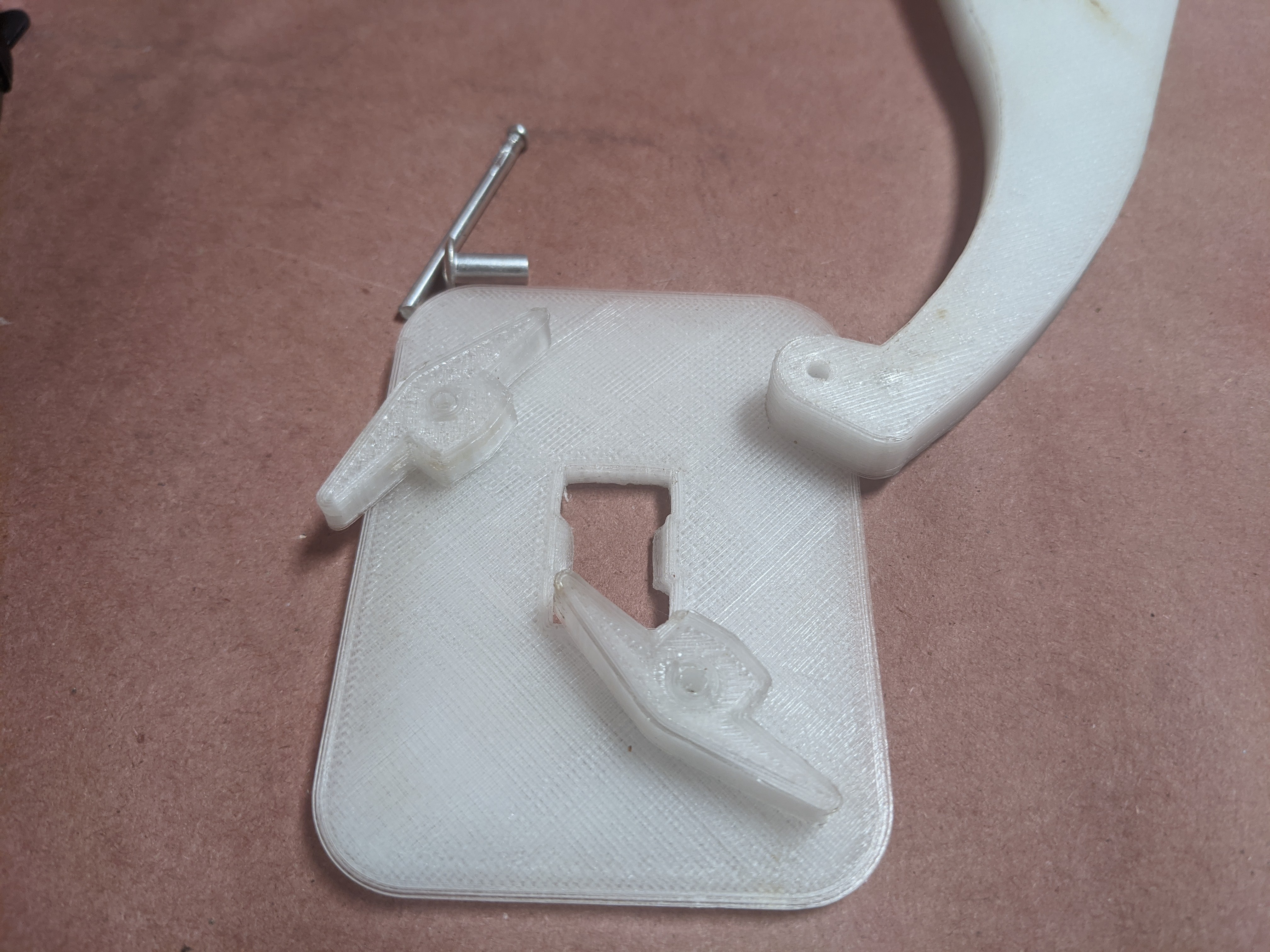
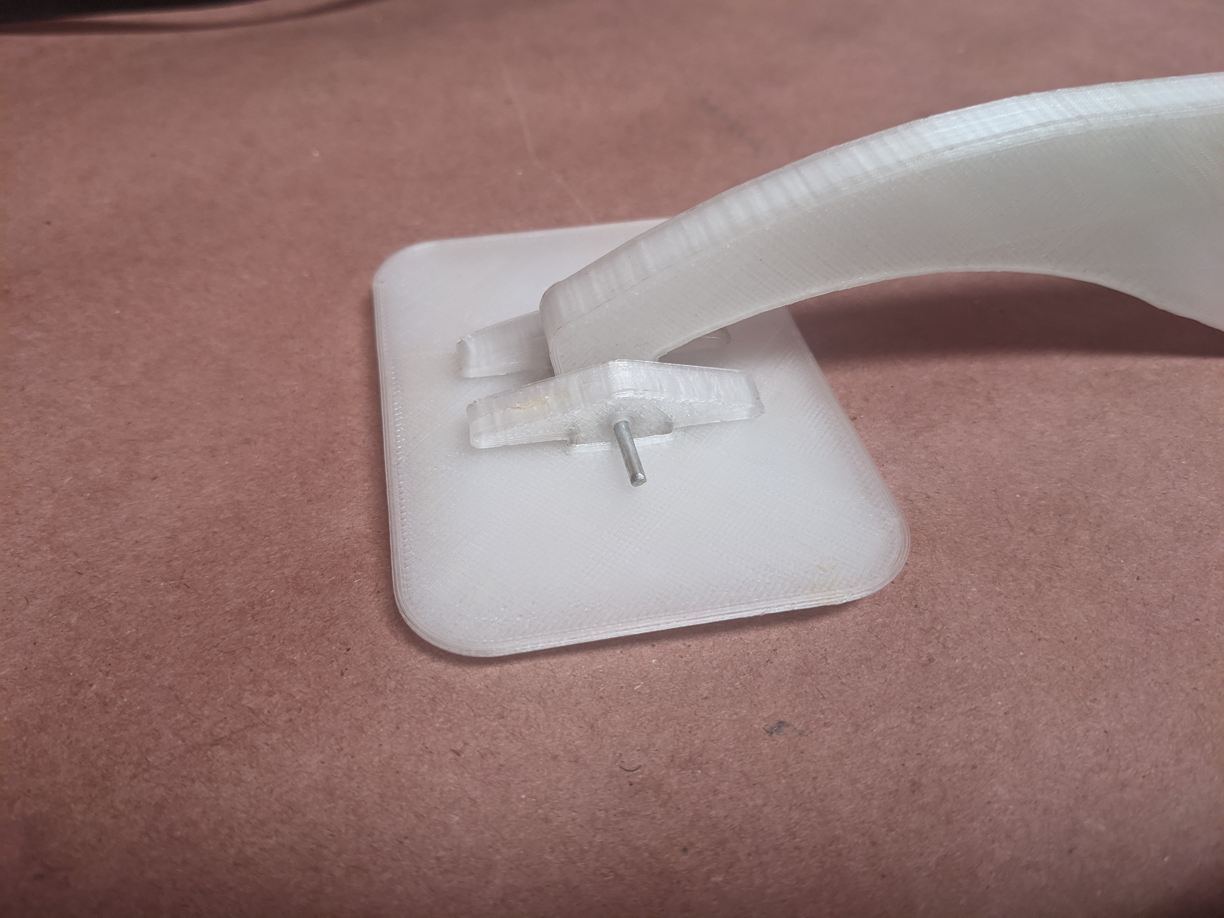
Hardware is done until testing reveals issues with it.  

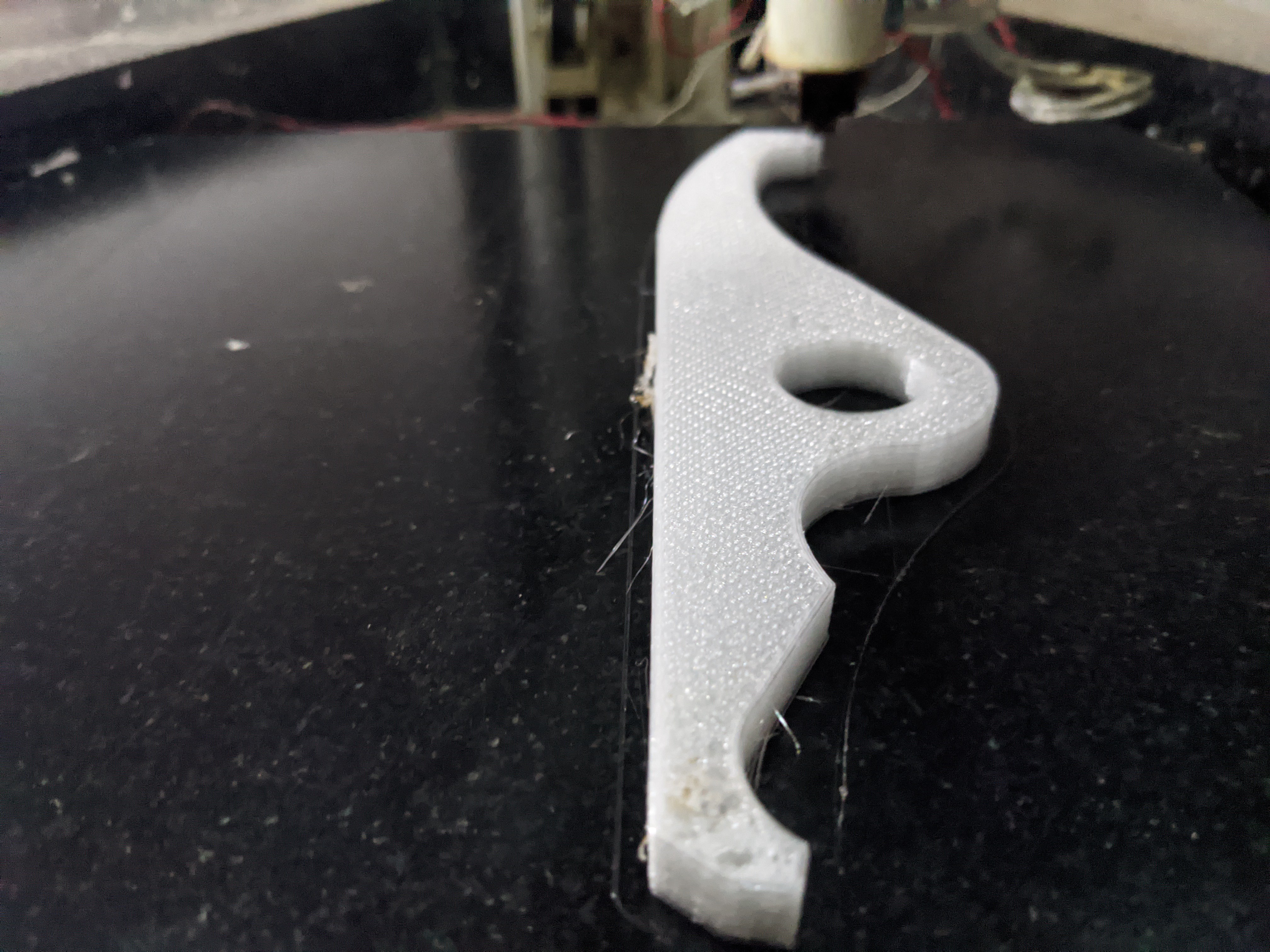
Source and rendered files are up on Github.  Laser cut files are here.  3D printable files are here.

So far you can use a BLDC gear motor, a small worm drive gear motor, or a Nema 23 stepper to drive this.

Torque requirement is 15-30 kg/cm and speed requirement is 22 to 30 rpm.

We need to deliver a faster inhale stroke than previously specified, so torque requirement is now 30 kg/cm and speed requirement is 48 rpm.  This may put it beyond what our (cheap) Nema 23 can do and probably puts my first pick for the BLDC out of the running as well.  The previous number for inhale time was 1.5s.  I picked the parts based on 1s.  The actual time from the UK document is now 0.3s.  Ooof.  Everything gets harder.

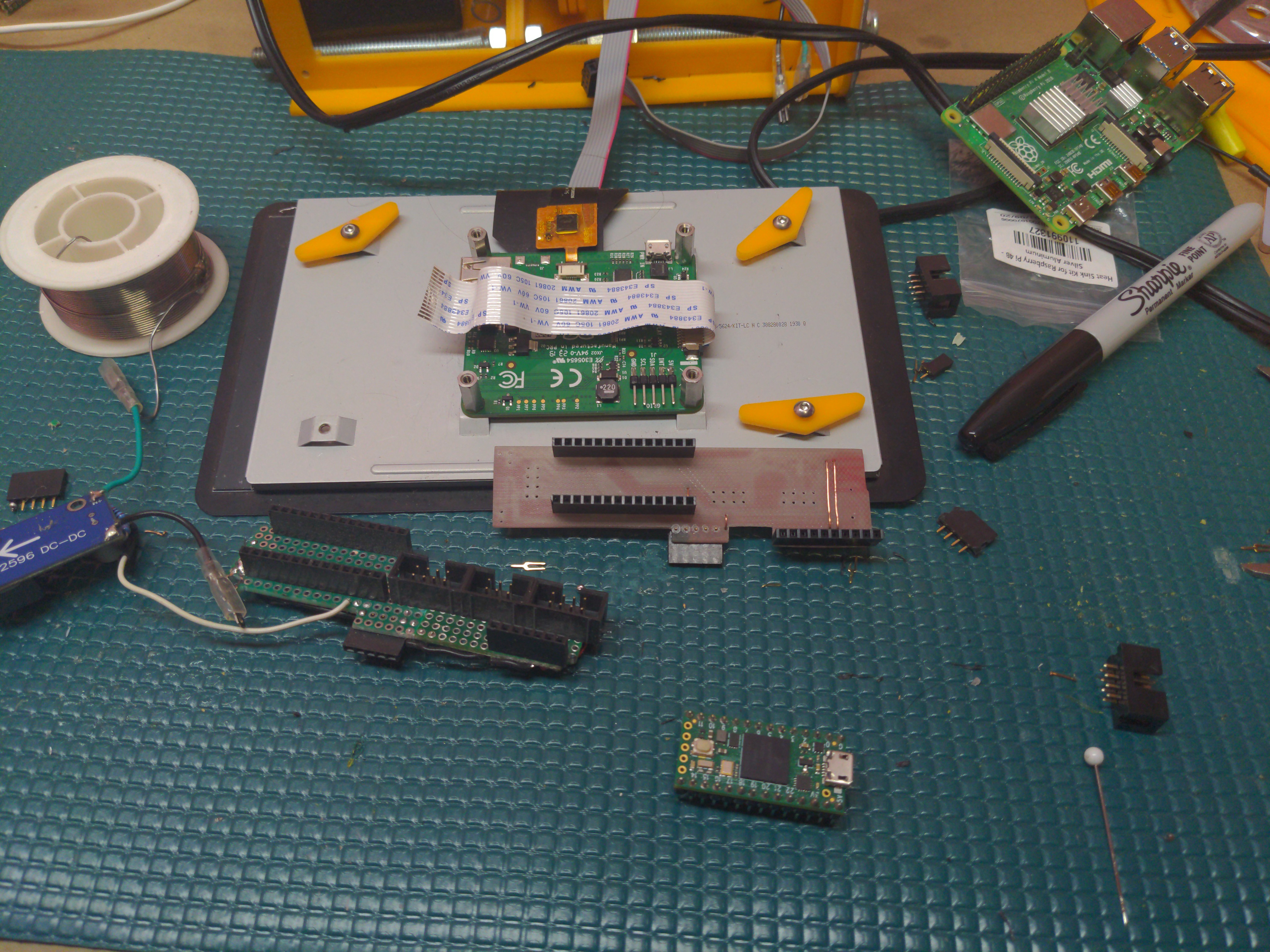
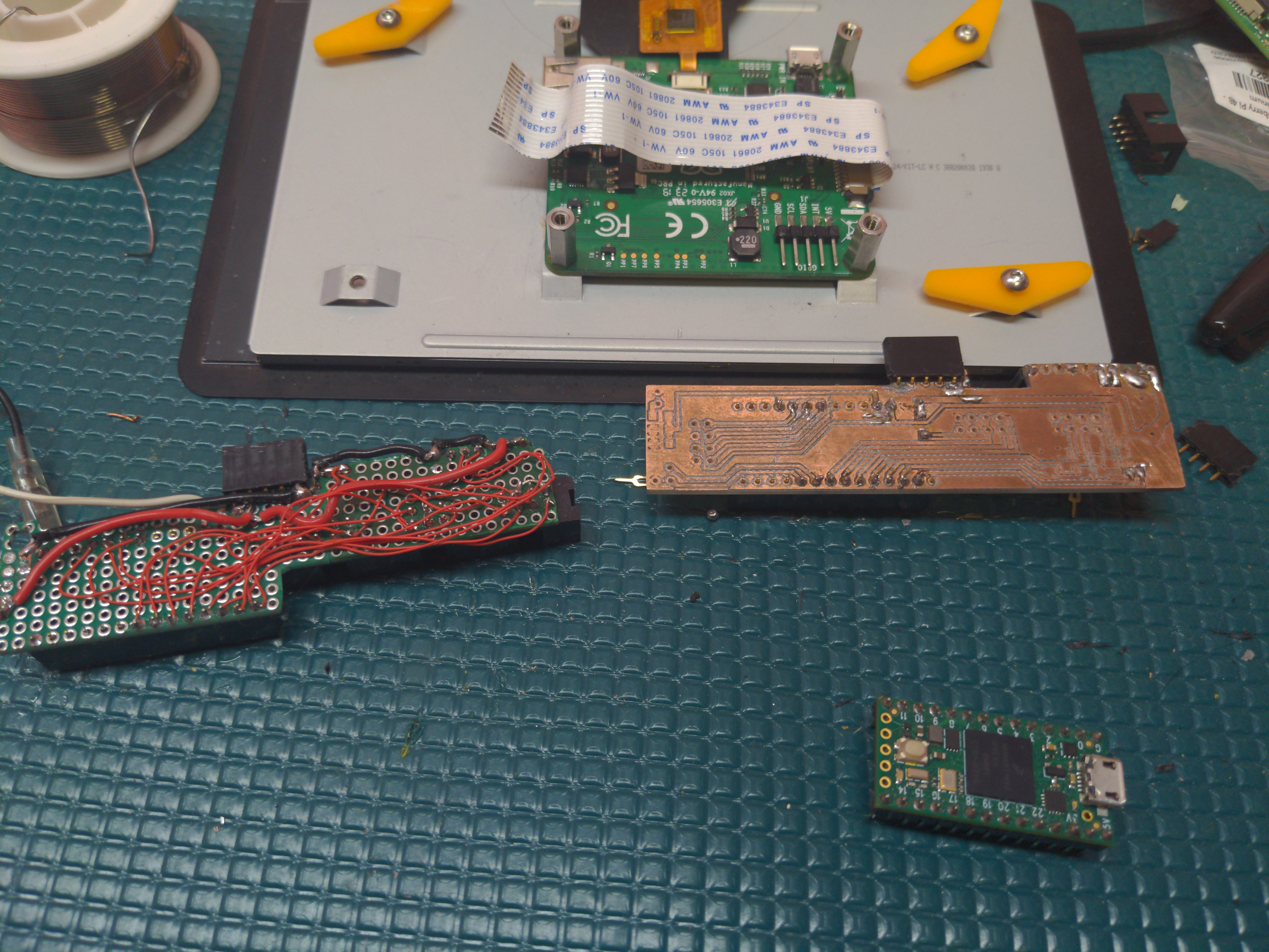
Electronics and sensing are sorted, but not completed.  Still missing some parts.

Software is in progress.  With the sensor stack in place, will be capable of assist ventilation, or static rate ventilation.

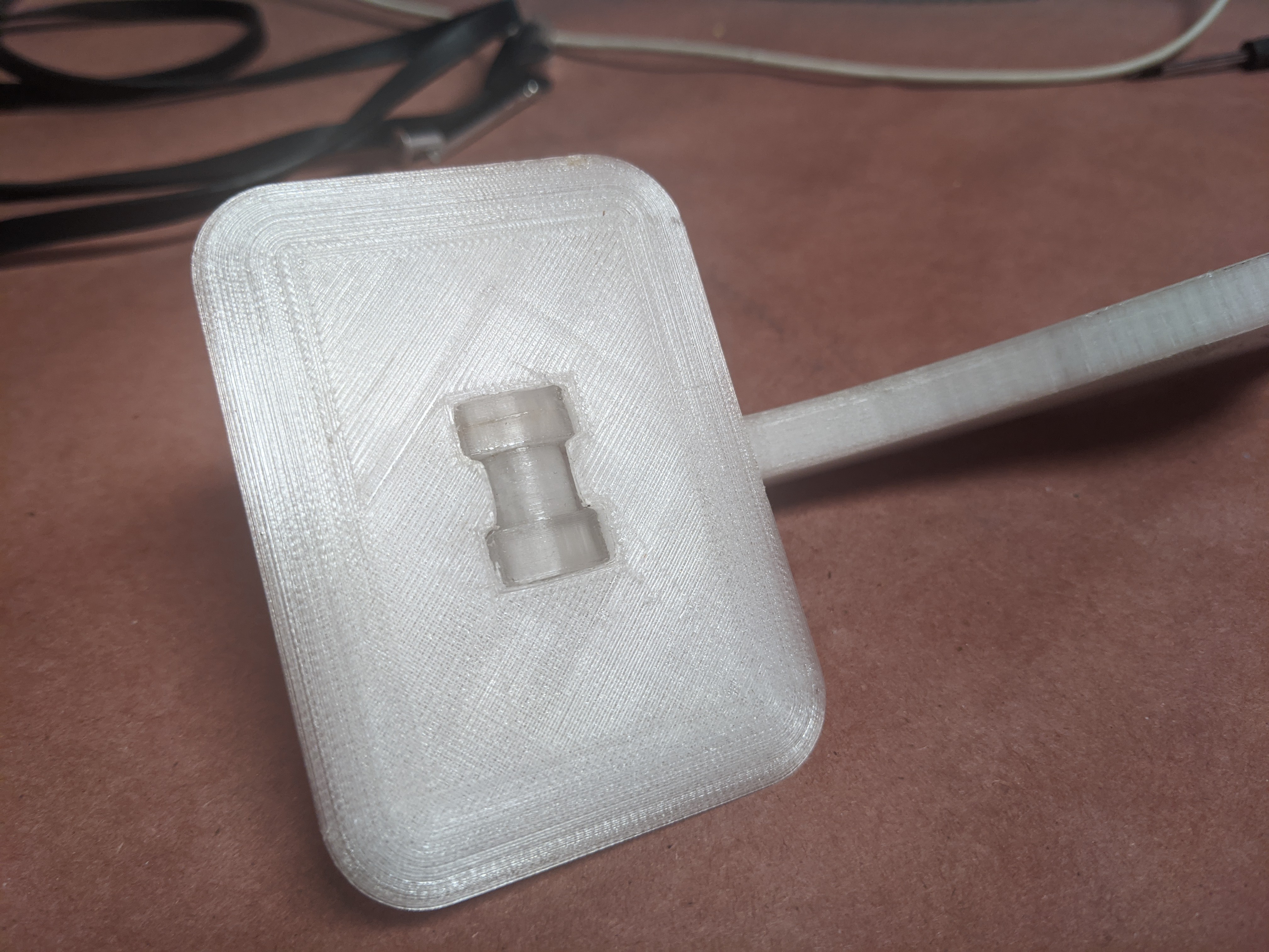
Pressure and volume delivered will be directly adjustable.  Maximum pressure will be configurable.  Maximum pressure should also likely be backed up by a physical pop-off valve.  We have a reliable 3D printed valve already developed for us.

MPEG-4 Video - 2.50 MB - 03/25/2020 at 19:55

Download

  • Riveting Results

    Daren Schwenke10/23/2020 at 19:48 0 comments

    The arm prints and the corresponding paddles/pivots did not turn out perfectly, but they will still work regardless and I suppose that is part of the point.

    I decided to use the post out of a rivet I had here as my retaining pin.

  • Open Arms

    Daren Schwenke10/22/2020 at 07:54 0 comments

    New arms, interchangeable with the laser cut version, printing in PETG.

    This version of the cam arm increases the compression stroke and allows for a parallel paddle position, but it does not compensate for the variable volume we have now during compression.   

    The variable rotation/delivered volume is complicating the PID loop we are using for our flow sensor feedback. We intend to compensate for the current non-linear flow with an inverted non-linear cam profile curve, but I haven't figured that out yet.  This is not for lack of trying though..

  • Good News everyone..

    Daren Schwenke10/19/2020 at 03:08 0 comments

    For the last several weeks, we have been working with a team of 12 *very* talented people, with very specific and content relative wheelhouses, with the ultimate goal of submitting this as a project for the fifth round of the VA/NIH/Challenge America Covid response effort.

    We had a product.  It was flawed.

    We gathered a *ton* of information from some highly qualified end users of this device, and then solved every problem that was solvable.  Sorry CPAP.

    As of a couple hours ago, this project just won the VA/NIH/Challenge America challenge, round 5, and so is a product that is moving forward.  Yay.

    I will document the full extent of what this entailed eventually. (famous last words for me)

    Congratulations and great thanks to the team of people who helped to make this happen.

    Thank you Thun Sanadi.

    Thank you Steven Carr.

    Thank you Kevin Patel.

    Thank you Cielo Borrinaga.

    Thank you Ray Williams.

    Thank you Abigail Brown.

    Thank you Michael Passalaqua.

    Thank you Jacquelyn Gill

    Thank you Jubei Marcado.

    Thank you Kevin Cox.

    Thank you Geron Rogers.

    and... Thank you James (Ben) Hoggatt.

  • Sigh.

    Daren Schwenke09/14/2020 at 20:49 0 comments

    #DP Ventilator just made it to the finals of Hackaday prize without solving *any* of the core requirements of this type of ventilator beyond squeezing the bag.

    Uses one sensor.. so they can't detect if the hose is kinked, if a nurse turned on a peep valve, or if the patient is even still connected.  This *will* do the wrong thing in every one of those situations and harm the patient.

    It is also impossible to implement any proper ventilation modes like that. If you implement pressure-based control you need to have flow as an output. If you implement flow-based control you need to have pressure as an output.  Otherwise you simply can't do the right thing, again harming the patient.

    Uses a long hose between the ventilator and the patient guaranteed to build up CO2.  The valve and sensor stack needs to be connected at the patient or you never empty that hose.  The patient ends up breathing in 20% of the air they just breathed out over and over. You think wearing a mask is bad...

    Uses the sensing idea of barometric pressure sensors, poorly, we submitted back in February to HelpfulEngineering during the initial massive sensor shortage, with no credit.  It is possible they ended up here though without ever seeing that.  Probably likely actually given they missed so much of the mark.

    Is mechanically complicated and is much more likely to bind and fail with sliding elements.  We designed ours per the UK ventilator specification of surviving for a half a million cycles over two weeks.  

    Is unable to actually meet the UK ventilator specification of an inhale cycle time of 0.3 seconds at 15cm/H2O.  We started completely over so we could.

    This makes me sad.

  • To Prize, or not To Prize

    Daren Schwenke08/31/2020 at 05:29 0 comments

    I sent this as a message to the project chat channel a few days ago with an '@mention' for everyone who is currently listed as a project member, but I'm really not sure that worked as intended, so I am posting this here as a project log as well.

    The message, with some added information for the general public...

    I originally didn't submit this project for any contests as I didn't want to have that dictate the direction of the project. I have fallen victim to this myself in the past.

    I also didn't plan on this project getting drawn out as long as it did, but getting Covid myself and other IRL events have changed the timeline here.

    @Steven.Carr @Kevin Patel and I have finally been able to get back to putting this on the front burner again in the last week or two.  

    There is a new carrier board arriving from @oshpark  tomorrow generated by @Steven.Carr which supports both the inexpensive analog input/SPI display interface and the full blown and intentionally isolated Pi display version of the UI.  This methodology was employed so that we can move forward with a potentially far more useful UI without requiring exhaustive run level testing.

    There is also another run of the VISP project on the way with support for 4 wire multiplexed I2C and two sensors per port, and both Steven and I have the latest laser cut versions ready for assembly.

    When I started this project I also kept it close at first, but then later on I allowed anyone who wanted to join the project, to join. This has resulted in a bloated roster where the majority of people here who are members of this project have not actually done anything with regards to the project.  This is partially my fault for being a bad organizer and I accept that.

    However, If I *do* submit this for the HAD prize at this point, everyone who is a member will need to opt-in and accept the prize rules. With the current roster, I am not sure that would *ever* happen.

    So, I'm going to drop a notification here (in the team chat) for everyone to sort this out. Please respond to it if you wish to remain a part of the project and have the time/resources to actively contribute. Deadline for submission is Monday morning. I will be trimming the roster just prior to that.

    Thank you: @Jarrett @Thomas Stilwell @Ashish @Rob @alpha le ciel @Robert L. Read @Ben Hencke @markus schneider @TyGuy @Ilk @clive @Steven.Carr @Fred Finster @Lori M Cannistra @markus schneider @anisleader @Mark @harit trivedi @Enrique Ortiz @josep Guirao @AsmitaJha @Filosofia ArteyTecno @tonnyrichard @TheBluePhoenix @djeddleman @samarth golwalker @eduarda @nelson.kistan

  • Back at it.

    Daren Schwenke08/26/2020 at 15:21 0 comments

    Replaced out airwired board with a milled one.  Lifted some traces.

    Steven in the meantime created and ordered a new version supporting both the pi and the teensy standalone from @oshpark.

  • Sick.

    Daren Schwenke07/23/2020 at 14:56 4 comments

    I got Covid-19, and I got sick.  For a while, really sick.  

    Sleeping 22 hours a day is a thing apparently.

    My energy level for most everything dropped to nothing for a long time, but is now improving again.

    A month later now I'm still coughing from the after effects, pneumonia I'm assuming, but my energy level is finally improving.

    So, I should be able to be back at this come the weekend!  Wish me luck.

  • PCB encoder milling

    Daren Schwenke06/17/2020 at 06:59 0 comments

    @Steven.Carr has been happily milling out PC boards and laser cut experiments on his very nice equipment.  I was growing envious as I sit here airwiring stuff.

    Four years later, I finally got around to building the PCB milling attachment for #Arcus-3D-M2 - Mixed material filament printer .  I always had a couple extra AL end effectors and 12 extra mag balls for exactly this purpose.  Necessity is your mother.

    Took the HF Moto tool I had and machined a full depth collet for it to specifically fit the PCB milling bits I have been carrying around in my toolbox for the last 4 years.  The normal collets for this tool when presented with any side loading wear out in about 5 minutes as they are relatively soft brass, and only hold the first 3mm of the bit.

    I also drilled massive holes in the housing to try to cool the motor a little better so it doesn't melt its mounts when running continuously.   

    This little motor does actually have *one* nice bearing in it, and carbon block brushes.  It may actually do okay for a while now.

     Anyway... The results.

    This part is the PCB that holds the two optical encoders we are using which allow us to turn DC motors (a Ford F150 wiper motor) into proper servos for about $4 in parts.

    I don't know if it is intended to be offset like that or not.  I assume so because I actually ran it twice as I got the depth wrong the first time.

    I just took the gcode that @Steven.Carr  ran on his Tormach (envy) and stripped out all those unnecessary things like tool changer commands and actual spindle speed speed control, and reduced the depth of the drill cycle to just give me the centers by relocating Z=0 with a G92 before it.

    Then again using a Tormach to mill PCB's is akin to using a pulse jet engine to spray sanitizer.  Yes, I am referencing you ACME Creation Labs.

    And.. a video.


    I was pretty conservative with my feedrates as I had no idea how this would do.  

    Steven ran this at F3.0.  I turned that down to F1.0, but ended up running the trace etching at F3.0 via feed rate override, but then dropping it to F0.6 for the final pass cutting full depth on the cutout.

    I also discovered my 3D printer UI does not properly handle running in G20.  Imperial coordinate systems FTW.  I am choosing not to fix that.

  • Laser kerf test

    Daren Schwenke06/09/2020 at 21:59 0 comments

    Made a test jig for determining the proper setting for laser kerf.  

    You stick a bearing in the holes until it fits, and the number above that hole is your laser kerf.  Similarly the slots below are for testing the edge joint kerf.

  • Drama

    Daren Schwenke06/05/2020 at 04:46 0 comments

    We have some.  

    We should not.  

    This is not a judgement on anyone involved in said 'Drama'.  Mistakes were made, but I don't believe anyone actually intended for the 'Drama' happening right now, to happen.  

    I chose not to believe that.

    In any case, I basically burned myself out and was physically ill for a while, and so I personally have done very little in the way of actual work on this project.  Sleeping was far more attractive and probably much better for me.

    In the meantime the laser cutter I was using to prototype my parts here 'went away', the city is on lockdown, the AC is not working, and I then I enticed a few very time consuminmg things to bite me.  It has not been a good week.

    We will prevail.

    I do have *one* working prototype though and through the significant effort of @Steven.Carr probably multiple modes, servo control of the motor subsystem, failure detection of individual components, etc.  Working is a relative term here as I still have yet to fix what may just be a simple serial issue to even find out.  Basically he wrote a pure C version of what I did in Python/Kivy for the UI and the serial protocol to implement it, in what seemed like a day.  Bastard.  :)

    At this point though I can probably get to that... um... Sunday.

View all 35 project logs

Enjoy this project?

Share

Discussions

Mr Name Required wrote 04/08/2020 at 22:43 point

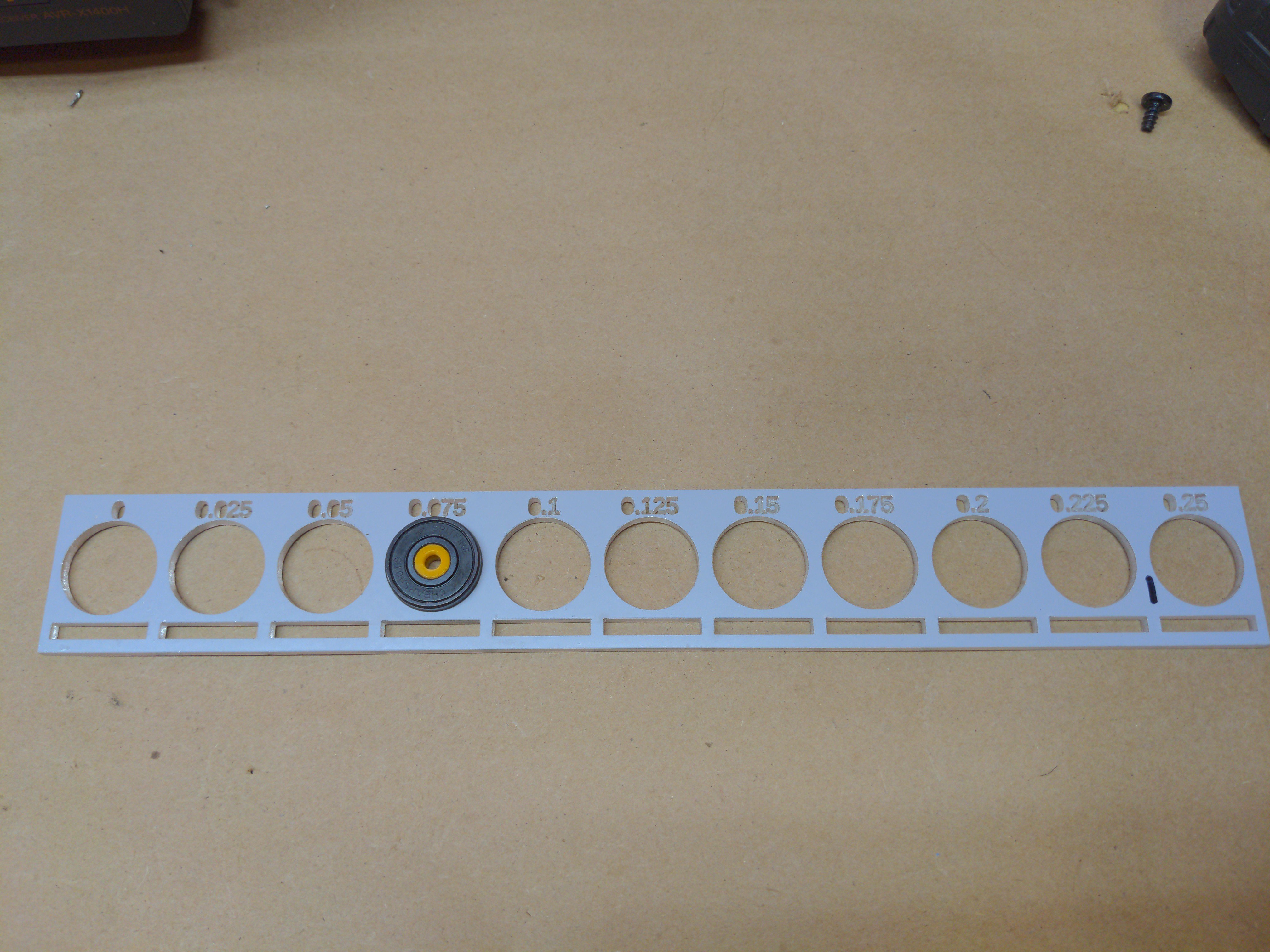
This is a fantastically worthwhile project, kudos for the design. Just a comment on the OpenSCAD script - bearings are almost always referred to by their diameters: OD, ID, width rather than in radii. It is easy to seach eBay and engineering supplies using the diameters for ballraces.

  Are you sure? yes | no

Daren Schwenke wrote 04/09/2020 at 04:20 point

Yes, and everything in OpenSCAD is radius.  :)  Rather than use diameter for just these, I put them in as D/2.  

These are just 608 bearings, aka, skateboard bearings.  No engineering store needed.  I should probably document that..

  Are you sure? yes | no

Eden Harrison wrote 04/04/2020 at 11:02 point

Hi, this is a really great project, really exciting to watch it move forwards!

I drew this up as a response to worries about the arms suffering fatigue damage, and to keep the ball rolling with bvm style pandemic ventilators. 

https://hackaday.io/projects/hacker/547432

I'm doing some fluid mechanics work at the moment and would be happy to help out where and if you need it. Otherwise good luck with future development. 

  Are you sure? yes | no

Daren Schwenke wrote 04/08/2020 at 22:04 point

Just finished reworking the models targeting acrylic as the material.  I hope to get them cut today and then hopefully a visual aid will emerge.  Thank you for the offer.  You are welcome to join us if you like.

  Are you sure? yes | no

Ocelot wrote 03/30/2020 at 18:05 point

Hi, I don't know if you were able to find an up-to-standard motor yet. I found this company, based in *Corona*, CA, that might carry what you need. 

https://makermotor.com/

  Are you sure? yes | no

racoon wrote 03/25/2020 at 10:48 point

Have you looked into automotive MAP Sensors? a lot a older car model were using these before MAF sensors. They mesure absolute vacuum and pressure.

https://www.aa1car.com/library/map_sensors.htm

  Are you sure? yes | no

Daren Schwenke wrote 03/25/2020 at 16:04 point

And work by heating resistive wire and measuring the amount of power required to maintain a certain resistance.  The heated wire part, in my opinion, made it unsuitable for O2 use.  But thank you for your suggestion.

  Are you sure? yes | no

racoon wrote 03/25/2020 at 16:22 point

no that is a MAF (Mass air flow) sensor. The heated wire react to the flow of air making if colder.

A MAP sensor is a pressure sensor and work just like your differential pressure sensor but measure the absolute value. So at rest It would have a measure of the atmospheric pressure. But you could log that value at startup and then go on with measuring pressure when the system is working. Look at the section in the link called "Analog Map Sensor"

You can tell the difference between the two type of sensor by their shape. A MAP sensor only has a small input tube without output

A MAF(the wrong one) is made to fit into the intake tube to be exposed to the airflow

Example found on amazon:

https://www.amazon.com/Pressure-16212460-Chevrolet-Oldsmobile-2000-2002/dp/B01N7DHRM5/ref=mp_s_a_1_9?keywords=map+sensor&qid=1585153828&sr=8-9

Typical shape, usually 3 wires, 5v GND and signal (analog)

  Are you sure? yes | no

Daren Schwenke wrote 03/25/2020 at 19:38 point

@racoon Ah.. that is more useful.  Wonder if they got one in 22mm, or one where the sensor and the pitot are split....  The latter would be very, very useful.

  Are you sure? yes | no

racoon wrote 03/25/2020 at 21:05 point

Unfortunatly there is no pitot in those sensor, it has a internal reference chamber and the input chamber so if you need two test points, you need two sensors. They are used to measure absolute pressure since its necessary for an engine to know if air is more dense or no (read different altitude)

  Are you sure? yes | no

diego.diez wrote 03/25/2020 at 22:04 point

A think that @racoon was thinking in one of those:

https://www.tme.eu/html/EN/pressure-sensors-mpx-series/ramka_2253_EN_pelny.html

you should be carefull in the selection of the sensor, cause there are absolute, relative (with two inputs) and relative to ambient pressure and everyone is for an specific purpose.  For the small research I have been doing, the more usefull for medic purposes are the absolute (but please do some research), if the absolute sensor gives you "real" readings that you do not need to calibrate, thats a huge bonus, cause you can inform that in the GUI and a health carer could understand easily. Mind that the unit used is  cmH2O.
Sorry about my english. 

  Are you sure? yes | no

clive wrote 03/24/2020 at 08:34 point

Deeply impressed with your project.
I will be building it and try writing some software.
Is there a stl for the latest modifications?
Or openscad files?
Great work guys!

  Are you sure? yes | no

Daren Schwenke wrote 03/24/2020 at 15:48 point

The stl's that are attached are the latest, but missing two files I forgot to post.  I need to get around to actually pushing this up to github.

  Are you sure? yes | no

amd_athlonxp wrote 03/24/2020 at 04:49 point

Do you have make a simulation? The arm does not looks so stable.

It needs a slightly more organic shape.

You need to heat the air up a bit and increase the humidity of the air.

It feels very bad if the air is dry and cold.

  Are you sure? yes | no

Daren Schwenke wrote 03/24/2020 at 05:11 point

Thank you for your comments.  In PLA, the arms are at least 10x stronger than they need to be.  The members under only tension are 2.4mmx7mm.  The members under compression are 7.2x7mm.  In acrylic this number is lower, but I can increase/decrease the wall size with a single variable if needed.  I do have the means to have a finite element analysis performed, and I do have someone testing them to destruction as well.

Yes, it does need a better shape.  Once the cover is on the motor it will be more organic.  I was more concerned right now though with not wrapping up peoples hair on the cam.

Humidity was to be provided by bubbling the input O2 through water.  For warming the air, I was going to warm the water with a fish tank heater, only exposing the sealed glass area to it.  This doesn't help if the patient is not on any O2, but I'll cross that bridge when I get there.

  Are you sure? yes | no

Muhammad Bin Sohail wrote 03/23/2020 at 22:33 point

hello anyone help plzzz

  Are you sure? yes | no

Nazaret García wrote 03/23/2020 at 19:33 point

Really nice work!!! I love it! I'm a programmer myself, so it would be an honor to help you with this project! Let me know how I can help please!

  Are you sure? yes | no

Nazaret García wrote 03/23/2020 at 19:34 point

Plus: I have a medical doctor in my family so she can help us if we get stucked with something.

  Are you sure? yes | no

Daren Schwenke wrote 03/23/2020 at 21:00 point

Responded in PM.

  Are you sure? yes | no

Dan Maloney wrote 03/23/2020 at 16:54 point

Nice work, I like the design. Good luck with further development.

  Are you sure? yes | no

Daren Schwenke wrote 03/24/2020 at 04:32 point

Thank you.  Hoping to have this ready for DOD Project VULCAN Hack-a-Ventilator Hackathon.  Deadline is Wed at midnight.

  Are you sure? yes | no

TyGuy wrote 03/23/2020 at 05:07 point

@Daren Schwenke I might be interesed/able to help with some software - I will message you directly.

  Are you sure? yes | no

Similar Projects

Does this project spark your interest?

Become a member to follow this project and never miss any updates