Close
0%
0%

Oximeter do it yourself

In this period of isolation, I'm trying to build an oximeter with parts already in house. An oximeter is made by two leds and a photodiode.

Similar projects worth following
I'd like to measure the O2 saturation level (%) in my blood with an homemade oximeter. I'm not an expert of medical knowledge, so I'm sure that this project hasn't any diagnostic value. It's just an educational project to study how it works.

I've defined these 5 sections:

1) Oxygen saturation and Covid-19
2) How does an heartbeat sensor work
3) Measuring heartbeat by finding the peaks of the value from the sensor
4) Modify the KY-039 heartbeat sensor to find the oxygen saturation
5) How is measured saturation

1) Oxygen saturation and Covid-19

In this incredible period of our life we've learned a lot of things about viruses, lungs, surgical masks, soap and washing hands. Everybody read about symptoms like coughing, fever and breathing difficulties. We've also known that one way to measure this breathing difficulty is reading the amount of oxygen in our blood.

This measure can be read indirectly with a medical device called oximeter. You have probably already seen it, it's a non invasive device that is placed on a finger with some pulsating lights that do the work. 

You can find it on Amazon, for example this one here:
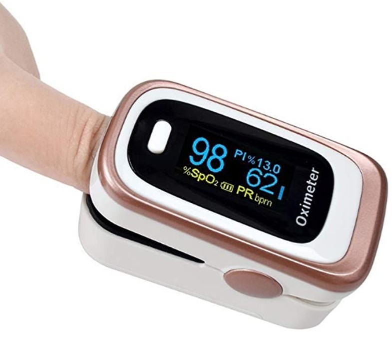
Normally, when you're ok, you have a percentage of oxygen saturation near or grater than 95%. When saturation goes down below 90% and you have cough and fever, it's a problem.

So we will try to build an oximeter! 


2) How does an heartbeat sensor work

To measure oxygen saturation, we first need to learn how an heartbeat sensor work. I've got an heartbeat sensor named KY-0039 which is made with an infrared led and a photodiode. The photodiode must be able to receive 940nm infrared light. Since we also need (in next steps) to receive the red light (if you're building the sensor from scratch) you will need a photodiode with a wide spectral range to receive light new 600nm (red) and near 940nm (infrared); this one seems ok: LPT 80A (but I'm not able to say if it's the exact one used in the KY-039 sensor).

I've found it in a kit with many sensors, you can see it in this pic (from internet):
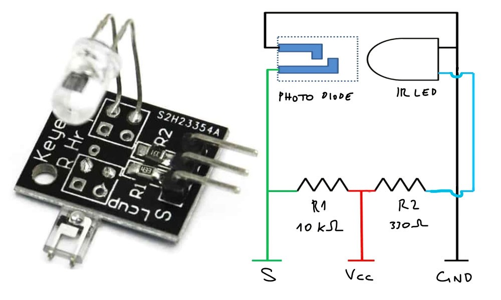
As you can see in the circuit, it's just a infrared led that lights a photodiode. There are also two resistors to protect the led and read the small signal from the sensor.  The finger is placed between the photodiode and the infrared led like this photo (from this site):
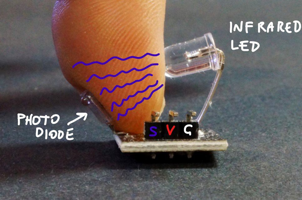
The light emitted by the infrared led is partially absorbed by the nail, the skin, and all the other parts of your finger, but it's not constant because it changes following the changes of the blood running in your veins. When your heart makes a beat the blood is pushed in your veins and the light absorption changes. With the S pin of KY-039 we can measure the current generated by the light absorbed by the photodiode.


3) Measuring heartbeats by finding the peaks of a signal from a sensor

Reading a good value from a variable signal it's not so easy, th signal is very low and there is a lot of noise, so we need to make some math to find values that mean something useful.

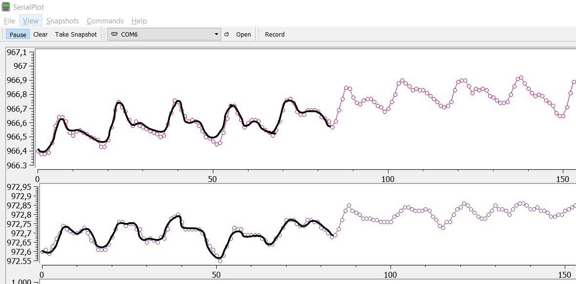
I've got to thank this useful post from Johan Ha, which explains how to plot the average of a small number of samples from the signal and it also explains how to remove the noise made by an home lamp (that light has a small noise). But I've also find that my heartbeat sensor records good signal with good ambient light, if I cover the sensor with a black cloth the signal has too much noise.

In its work Johan Ha makes an array in which push a value and drop a value to mantain the average of the last X values read from the sensor.

He has also described a way to find the rising of the signal, when there are N values growing (when a value is grater than the preceding value for N times), it is a peak.

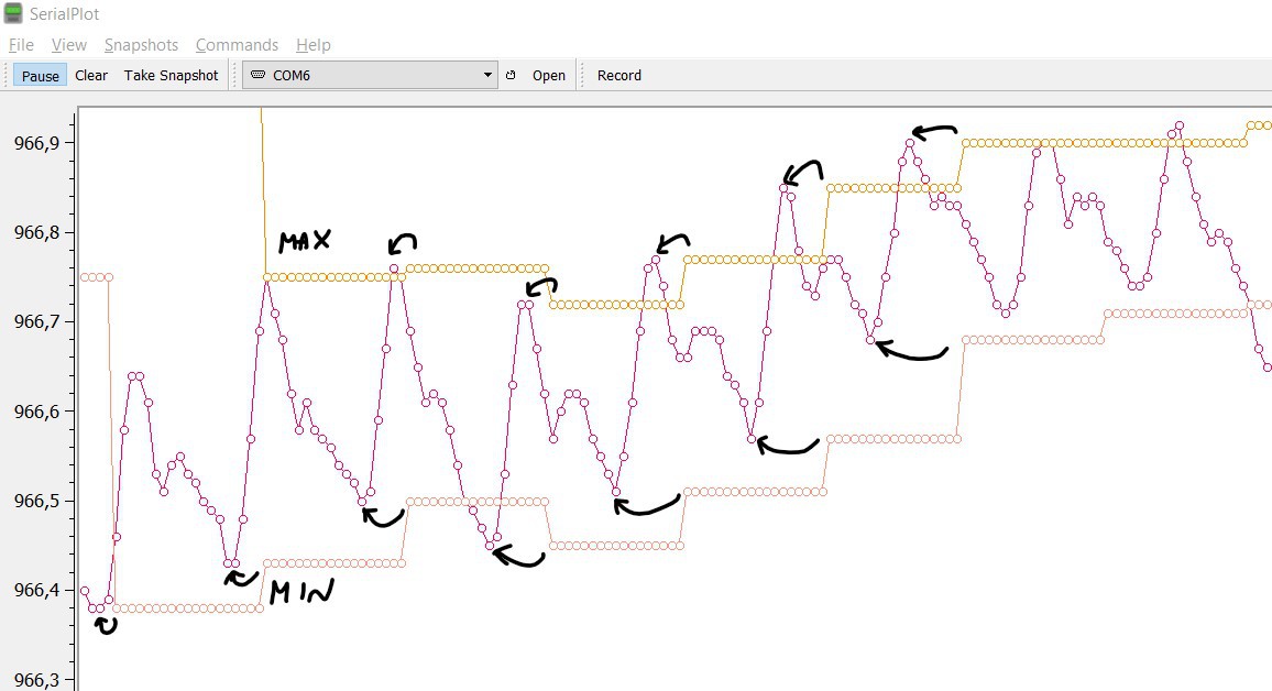
Using SerialPlot I've seen better the number of measures that allow us to define a correct N (rise_threshold constant in the code). In this chart below if you define a number grater than 7, for example, you will miss some beats.
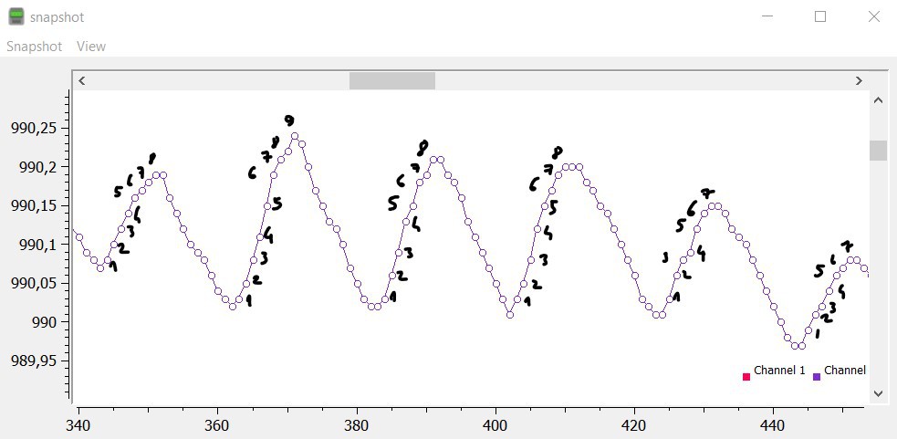
Once you've find the peaks, just count them, or calculate the time between a small serie of beats to determine the BPM rate (Beats Per Minute).

With these tricks, counting the number of peaks and BPM is quite easy.


4) How to hack the KY-039 sensor to find oxygen saturation

Our blood absorbs light in a different way with the change of the wave-length of the light. The red light is absorbed better by the blood with more oxygen, so we can compare the measures and find the percentage...

Read more »

oximeter-diy-ok-092.ino

ver. 0.92 display changes and fixes IR, RED, MAX, MIN, R, BPM, SpO2% And results stabilization

ino - 9.25 kB - 04/26/2020 at 08:42

Download

oximeter-diy-ok.ino

ver. 0.9 IR, RED, MAX, MIN, R, BPM, SpO2% And results stabilization

ino - 9.15 kB - 04/18/2020 at 22:09

Download

oximeter-diy.ino

ver 0.5 IR and RED plot heartbeat count

ino - 5.26 kB - 04/13/2020 at 10:16

Download

  • 1 × Arduino Uno
  • 1 × KY-039 heartbeat module If you don't have this sensor you can build it with 2 resistors and a Photodiode as described in the project
  • 1 × Red led
  • 2 × 330 ohm resistor
  • 1 × LCD 16x2 display I2C

View all 6 components

  • Building from scratch

    Giulio Pons06/07/2020 at 16:12 0 comments

    I've tried to build the oximeter from scratch, with a LTR-301 photo transistor and it doesn't work as expected.

    The problem is the LTR-301 spectral response which is quite narrow around 940nm. So it doesn't receive the red light!

    To build from scratch (without hacking a KY-039) we need to use a wide range photodiode, such as the LPT 80A which can receive both red (600 nm) and infrared (940 nm) light.

    Maybe finding a phototransistor with Srel (Relative Spectral Sensitivity) value around 600nm very similar to the 940nm (in this one it's 50%) is also better:

  • New video with 3-leds oximeter sensor

    Giulio Pons05/10/2020 at 10:01 0 comments

    I've improved the display visualization and this is a video with the sensor with 3 leds (white, red, IR).

    It detects faster the beats and the measures now do not depend anymore on ambient light.

    I've had also to re-calibrate the sensor.

  • Op amp

    Giulio Pons04/25/2020 at 21:24 0 comments

    Now I think that I should add an op amp to read better signals and have more stable measures.

  • How to get more precise values?

    Giulio Pons04/25/2020 at 13:19 3 comments

    I've got a big problem because this oximeter isn't effectively working fine. It works if there is enough ambient light from sun or from an electric lamp, but every time the light changes (just a shadow that passes over) the average value of the signals from the photodiode rise (less light) or fall (more light).

    These changing cause problems (or impossibility) to have correct and stable measures of saturation in every situation.

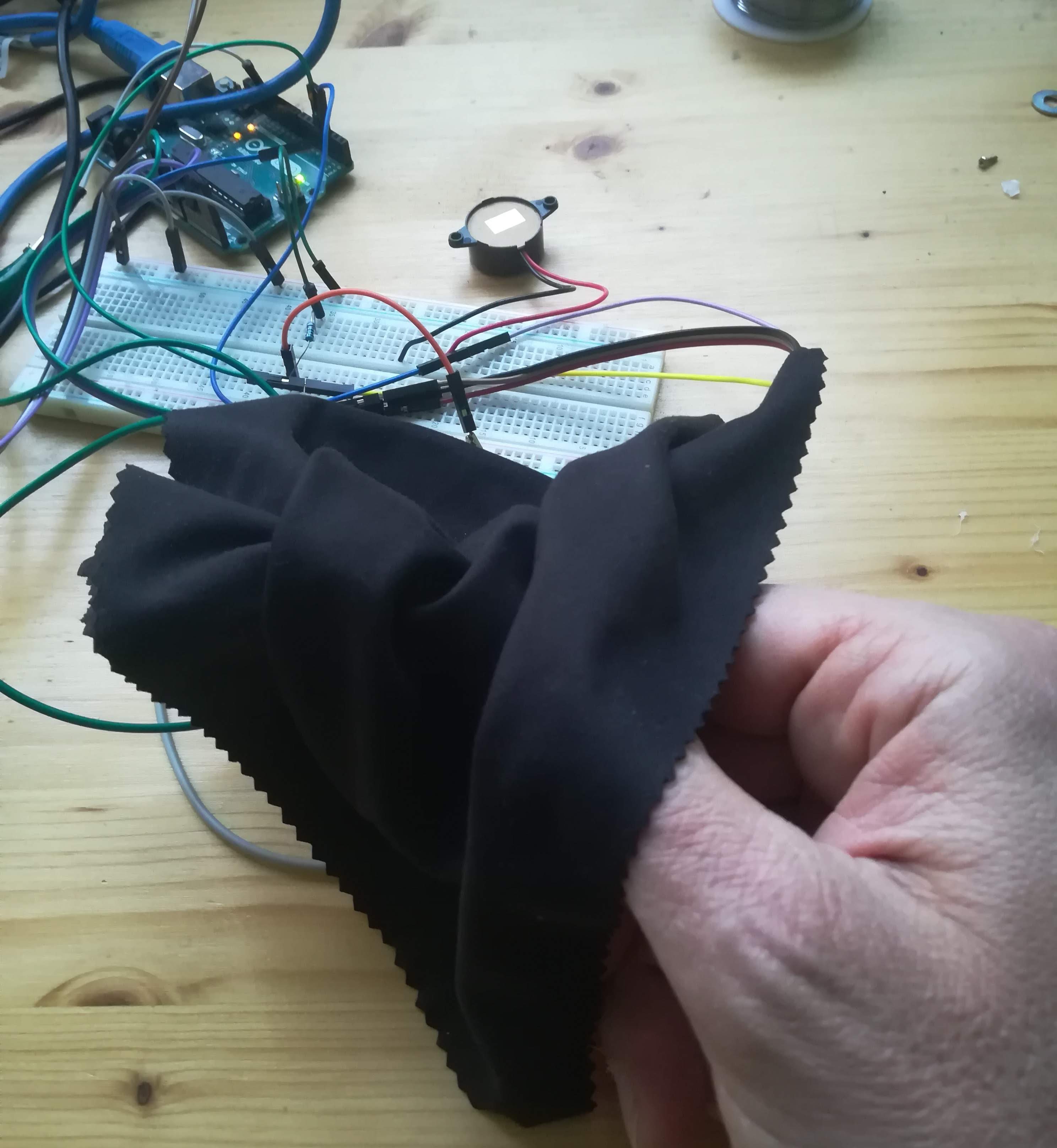
    So I've tried to cover the finger, leds and sensor with a black cloth, but the result become also worst. The photodiode signal is really obfuscated with noise that prevents the code to find peaks and then bpm and SpO2. 

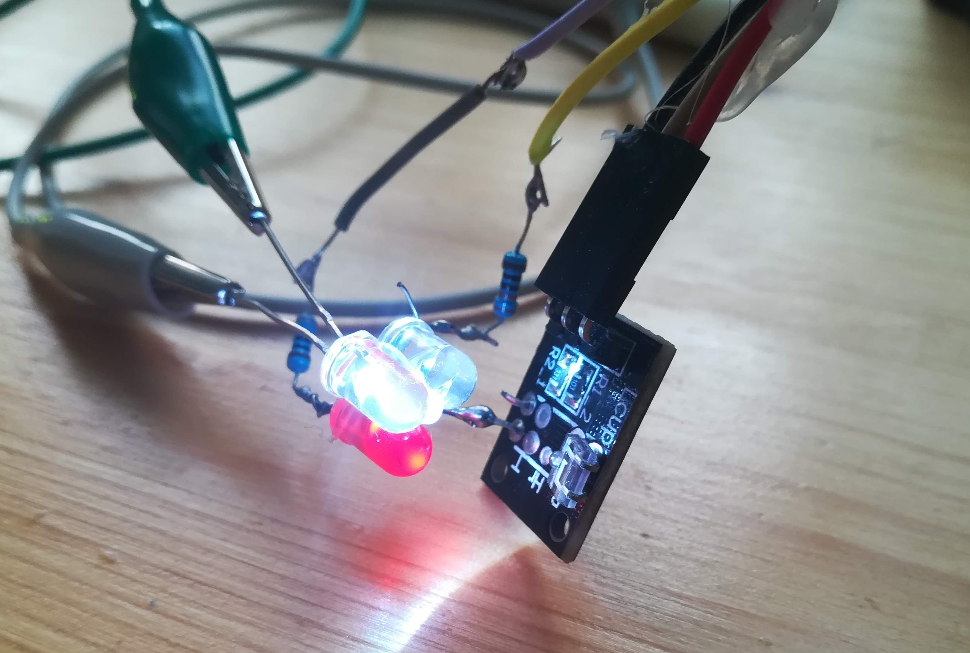
    Since it works better with some additional (ambient) light, I've added a third led, a white led. And decided to take measures with the black cloth covering all the stuff.

    The result is better than black cloth without third led and I can read signals again, but now the reads should be independent from ambient light.

    What do you think about it? Is this a bad idea?

    How can I get better values from the sensor?

    red - infrared - white leds
    the sensor is covered with a black cloth to have always the same conditions

  • Fixing erros

    Giulio Pons04/22/2020 at 07:33 0 comments

    I've updated the project details, there were so many english errors, and some concepts were not cleared explained, I hope now it is more readable.

    I've also uploaded the project to the The COVID-19 Detect & Protect Challenge on Hackster site, at this link

  • Calibration of the homemade oximeter

    Giulio Pons04/18/2020 at 22:15 0 comments

    In past days I've made the calculation of Min and Max of both IR and RED led signals.

    I've also calculated R and today I've found a working oximeter to calibrate mine.

    So, just updated the the code and completed the details.

    Next step: make a complete schematic with all the parts since in the project there is also a LCD display 16x2 to show bpm, SpO2%, and some other informations, while the plot of the signals is made with the PC.

  • Max, Min and R calculation

    Giulio Pons04/15/2020 at 21:45 0 comments

    I've modified the sampling parameters, after the average on 20mmsec (to remove electric light noise) I use 1 sample to plot the chart. You can see better the typical "dicrotic notch".

    Changing the number of samples that are averaged smooths the curves.

    I count the peaks, so I can estimate the period of the heartbeat, the period is the time between two rising curves. Knowing the period and the times I sample the signal I can determine how many samples there are in a period: I make a sample for IR (20 mmsec) and a sample for RED (20 mmsec), so every sample happens every 40 mmsec (I suppose calculation time is enough small) 

    Knowing this number, I can search in the last N samples for Max value and Min value. N is period/40.

    Now I have Min, Max and can determine every N samples the R coefficient.

    The period, N and R are not fixed. They are continuously calculated.

    I've tried to plot min and max, but when I plot they are not synchronized with the signals, because they are calculated a period later.

    Now. I have to connect R with Sp02, this work is known as "calibration" of the oximeter.

    Do I need another oximeter to calibrate mine?

  • Added the code

    Giulio Pons04/13/2020 at 10:08 0 comments

    I've added the Arduino code for my oximeter.

    At this moment it doesn't calculate SpO2 yet. It plots the two curves (IR and RED) and calculate BPM in two different ways. Next step: calculate the MIN and the MAX for each curve, calculate R and determine the function that connects R to SpO2.

  • Details updated

    Giulio Pons04/12/2020 at 15:39 0 comments

    I've updated the details of the project, I've added how I've modified the KY-0039 heartbeat sensor to add another led and performs a double read, using both red and infrared leds.

View all 9 project logs

Enjoy this project?

Share

Discussions

steamonlinegamer@mail.ru wrote 05/03/2021 at 13:00 point

Hi!This is a very interesting project. I decided to repeat it. But the Saturation values I got 104-107%. Please tell me how to make 95-99%. I'm not good at programming. Should I change something in the program code? If so, which ones?

  Are you sure? yes | no

piONE.jp channel wrote 09/17/2020 at 21:32 point

I'm sorry but, I think that the third LED will bad affect to the SpO2.

When you measure at multiple wavelengths at the same time, the AC/DC ratio will depends on your finger structure.
Therefore, the correction curve is not uniquely determined.

  Are you sure? yes | no

Giulio Pons wrote 09/18/2020 at 07:01 point

What a pity, I didn't know. The only way to read good values is to implement an op amp on the photo diode signal.

  Are you sure? yes | no

piONE.jp channel wrote 09/18/2020 at 08:43 point

Or, I think that you can reduce the LED resistance.

The destruction phenomena of LED due to overcurrent is related to the junction temperature.
In other words, if the periodic average of the current is about 20mA, it will not break.
So that if you set the LED ON time to about 10%, you can increase the LED current  by 10 times.
At this time, photocurrent also becomes 10 times.

Your circuit is simpler and more beautiful than mine.
But, it seems difficult to adjust.

  Are you sure? yes | no

Giulio Pons wrote 09/18/2020 at 10:00 point

Your suggestion to is awesome, I should try!

  Are you sure? yes | no

piONE.jp channel wrote 08/30/2020 at 05:12 point

Hi, I have a question.
How do you read Analog level?
Arduino ADC will not have enough resolution.
It seems that the decimal point can be measured from the graph.

  Are you sure? yes | no

Giulio Pons wrote 08/30/2020 at 08:41 point

No, decimal points are the results of calculations, I'm not plotting directly the values from the pins, they are summed and averaged.

  Are you sure? yes | no

piONE.jp channel wrote 08/30/2020 at 13:35 point

Thanks.

I read your code.

By integrating the hum noise for one period, did the step noise due to the low resolution gone?
I want you to try what happens if you connect the body ground and reduce the hum noise.

  Are you sure? yes | no

gregorio.bussyguin wrote 05/16/2020 at 19:21 point

Hey Giulio, i was trying to make this project (freaking awesome btw), and as i uploaded the code to my arduino the numbers for the bpm,SpO2,C and r were shown, but, the respective names for them, such as "bpm" and other did not appear. What did i do wrong?

Btw, sorry for bad english, its not my first language. 

  Are you sure? yes | no

Giulio Pons wrote 05/20/2020 at 16:53 point

It doesn't happen to me. The code should write the labels when remove the "No finger?" string from the screen. I'll have to check it.

  Are you sure? yes | no

jordano wrote 05/11/2020 at 13:27 point

hello, on this site you can see the problems that you reported regarding the brightness. finger size and position also influence. Perhaps changing the position of the LEDs can help with this, as well as in the max30100 sensor.

https://www.howequipmentworks.com/pulse_oximeter/

  Are you sure? yes | no

Giulio Pons wrote 05/11/2020 at 14:02 point

thank you for the link! I'll read it soon. Also the position of the LEDs change the results.

  Are you sure? yes | no

Drew Pilcher wrote 04/16/2020 at 19:47 point

Great project! I would calibrate the device by buying a chinese pulse oximeter and comparing the readings. You can hold your breath to make it go down.

You could also just assume your blood saturation is 99% and use that, not sure if you need a second data point.

  Are you sure? yes | no

Giulio Pons wrote 04/18/2020 at 21:36 point

Hi @Drew Pilcher  yes! I did it. I've found another oximeter and hold my breath to calibrate mine! Now I'll upload the complete source. 

  Are you sure? yes | no

Similar Projects

Does this project spark your interest?

Become a member to follow this project and never miss any updates