danjovic
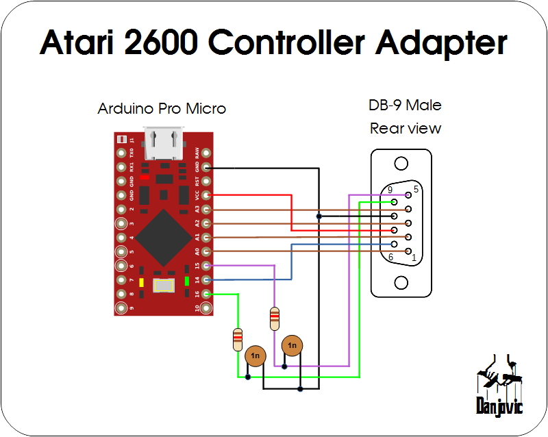
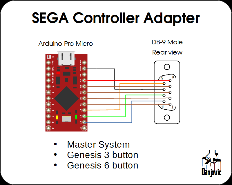
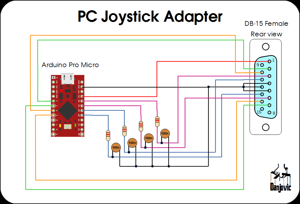
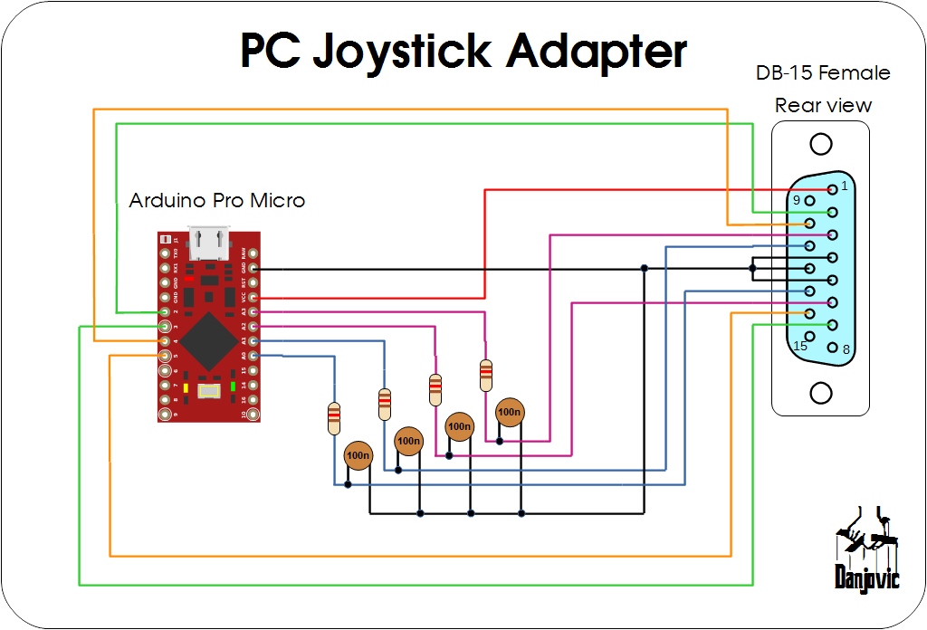
The base circuit uses a cheap Arduino Pro Micro that come up with an ATMega32U4 chip that yields native USB connectivity.
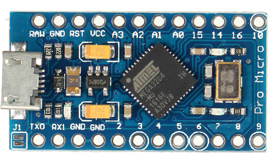
Such board combined with HID-Project provides classes for several HID devices including a resourceful game controller with 6 analog axes, 32 buttons and a 2 D-Pads (hats)
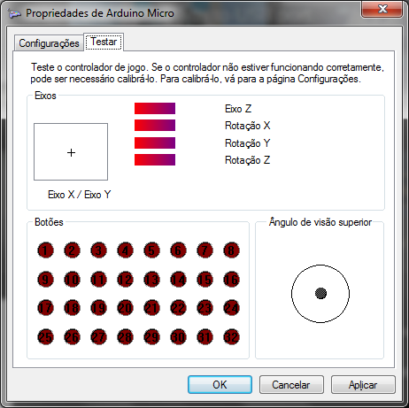
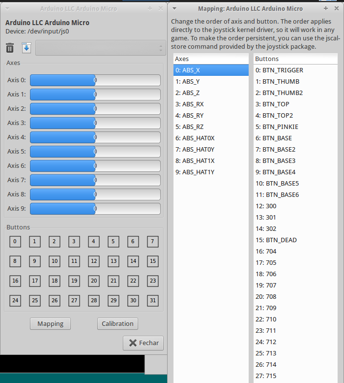


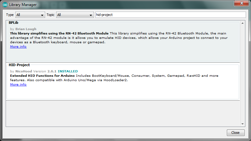 After install the library the HID-Project examples should be available
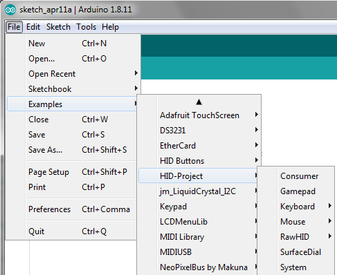

 Evo
Evo
 The Big One
 Jacques Gagnon