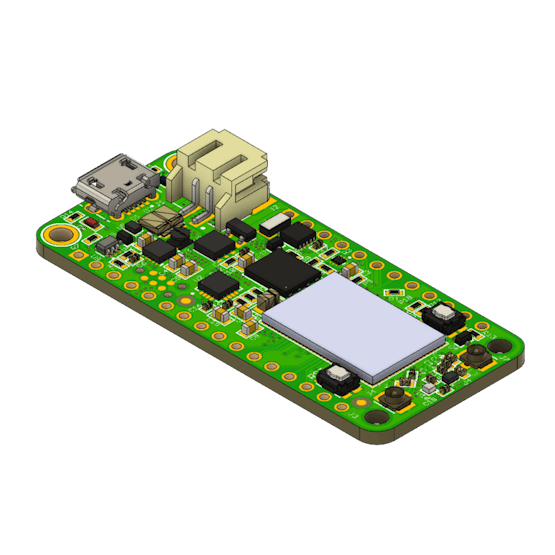
-
The nRF9160 Feather Is Now Served
08/01/2020 at 03:43 • 0 comments![]()
I was a complete failure. My prototype wasn’t working. I spent at least an hour trying to rework a frustratingly large LTE module on an impossibly small circuit board.
It wasn’t going to work.
So I went back to the drawing board. I poured my years of hardware experience into a tiny form factor.
The end product?
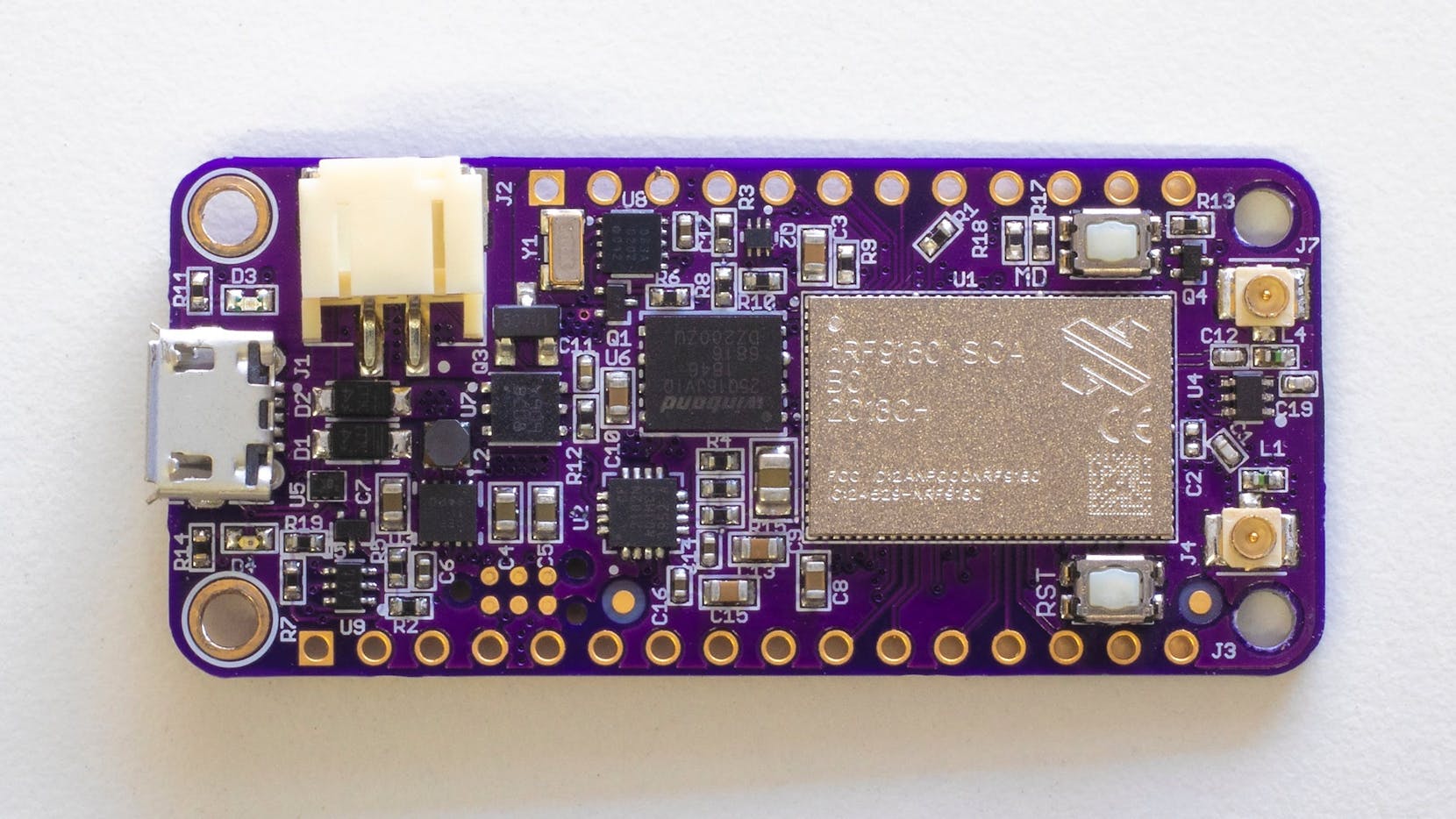
Something smart. Something with LTE, NB-IoT, and GPS. Something anyone could get started with right away.
And thus, the nRF9160 Feather was born.
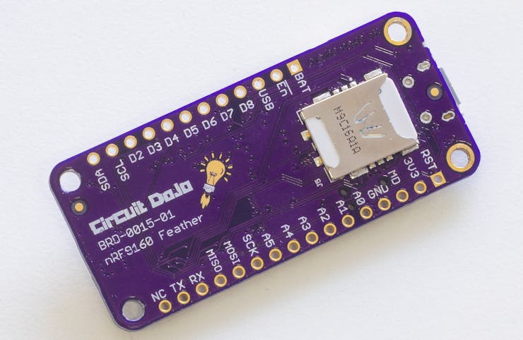
The nRF9160 Feather Video! The nRF9160 Feather brings all the features I’ve been craving into a familiar package. Things like low-power shutdown capabilities, built-in 4FF SIM card slot, flexible power supply, and 2MB of external flash. Plus, everything else you’d expect from Feather form factor board.
![]()
Plus with a company like Nordic Semiconductor behind the nRF9160, I knew it would be something I’d find myself using every day. I didn’t want to be the only one though.
Open source
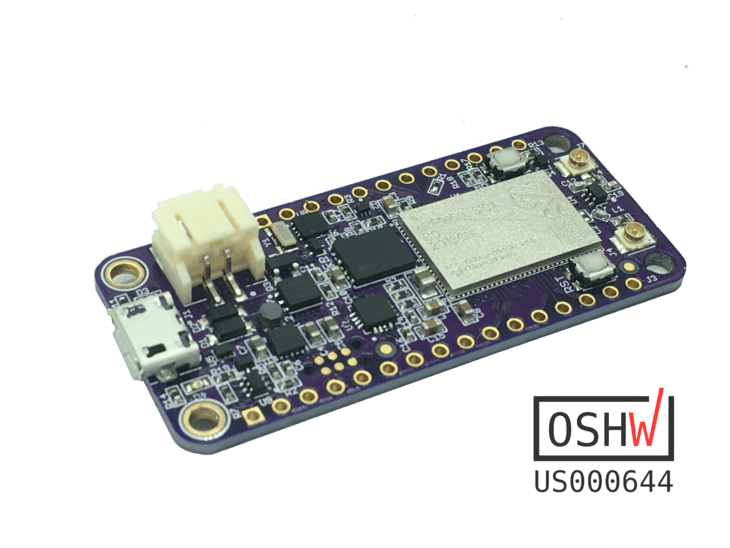
![The nRF9160 Top + OSHW Cert #]()
The nRF9160 Top + OSHW Cert #
I could have been secretive about the development of the nRF9160 Feather. Instead, I wanted to share its’ story with everyone. See, the best way to learn is to see and then do. That’s how I built my very circuit board back in 2007 with nothing but some rudimentary knowledge of how EagleCAD worked.
So please, I encourage you to check out the documentation, download the source, and start tinkering. The hardware is under the CERN v1.2 license which is fairly permissive. For more information, check out the campaign page.
How do I use it?
Great question.
The nRF9160 runs on Nordic’s nRF Connect SDK. If you’re a Microsoft Visual Code user, you can check out how I got started. That way you don’t have to go through the same pain I did!
Once you’re setup, the nRF9160 Feather works with many of the SDK examples. For example, compiling and flashing the
at_clientfirmware is as easy as:cd ncs/nrf/samples/nrf9160/at_client/ west build -b circuitdojo_feather_nrf9160ns -p west flash
Where am I?
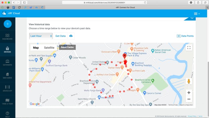
![nRF Cloud GPS Plots]()
nRF Cloud GPS Plots
The nRF9160 Feather has worked with all the active GPS antennas that I’ve tested. Simply attach one, load the firmware and go.
I used the
nrf_cloud_agpsexample (with some slight modifications) to track a recent jaunt around the neighborhood. You can see the path in the screenshot of nRF Cloud above. Many of you have expressed interest in tracking your personal belongings like bicycles, cars, etc. This will get you started in the right direction, fast.So much more
Since the nRF9160 Feather has been added to Zephyr, you can almost use any example or sample. Many of the nRF Connect examples work with minor adjustments. Here are some of the other examples I’ve used with great success:
nrf/samples/nrf9160/https_client- does the equivalent of an HTTP GET on https://www.google.com using SSL.nrf/samples/nrf9160/gps- basic GPS example with an optional SUPL library that uses Google’s SUPL server. This is a form of assisted GPS that helps get fixes much faster on cold start. (We’re talking about orders of magnitude faster.)nrf/samples/nrf9160/lte_ble_gateway- a great example for connecting you nRF9160 directly to other Bluetooth devices using Zephyr’s HCI Bluetooth library. It works specifically with the Thingy52. You can adapt it for other devices as well.nrf/samples/nrf9160/mqtt_simple- establishes a connection with a MQTT server. It subscribes to a topic and replies in an echo so a separate “pub” topic. It’s a great example to start working with an MQTT solution that may not involve AWS.Cellular service required
The nRF9160 doesn’t connect to the outside world without cellular service though! Here in the states most of the carriers support LTE-M only. This includes AT&T, Sprint, and Verizon. While there are others, my tests have shown they don’t work.
Fortunately, backers of the project receive an included SIM at no extra charge.
![Hologram SIM]()
Hologram SIM
Usually, a single SIM from Hologram costs upwards of $11 with shipping depending on where you are. Once you get it, sign up for an account here,and then activate your SIM in their console. Then, slide your SIM into the bottom of your board and get rolling!
What’s next
The nRF9160 Feather compliance progress is still ongoing. That means more testing before it can conquer the world.
These “badges” are in the form of compliance testing to make sure the nRF9160 Feather is operating safely. At the minimum, the nRF9160 Feather will be FCC Part15 and ICES-003 compliant. That means you can use it stand-alone with no added testing whatsoever. Awesome, right?
The catch? I need your help.
I need your help! 🙏
To make this campaign a reality, I need your help to meet our minimum order quantity of nRF9160 Feathers. Without that, we’re dead in the water! Head on over to the campaign page to reserve yours.
Picture credit goes to the wonderful folks at GroupGets.
-
How To Add Bluetooth to your Zephyr powered nRF9160 Feather
08/01/2020 at 03:43 • 0 commentsOne of the cool things about Zephyr is its modularity. It’s also one of things that makes development on the platform difficult. This is especially true if you’re not use to the recursive nature of CMake or how to configure it in the first place!
Despite these setbacks, I was able to configure the nRF9160 Feather to be used as a fully fledged Bluetooth device! In this post you’ll see some of important steps and learn from my experience of starting “from scratch.” That way you don’t have to do it all yourself!
So without further ado, let’s begin!
An RTOS With Some Serious Features
Let’s start with an easy example. Then we can wade into something more.. complicated.
Does you project have USB? Add a few lines in your
prj.confand voilà, presto change-o, and you have a USB Console!Don’t believe me?
I took a Particle Xenon I was using and got searching through the Zephyr repository. I searched for maybe a minute or two until I found the correct definitions. Fortunately. there were a few other samples in the Zephyr repo that use the same features. That made the search much easier!
You can add this to nearly any project. Just make sure that your device has USB and that it’s definied in the Device Tree. For now we’ll assume you’re using a nRF52840.
CONFIG_CONSOLE=y

CONFIG_USB=y
CONFIG_USB_DEVICE_STACK=y
CONFIG_USB_DEVICE_PRODUCT="Xenon"
CONFIG_USB_UART_CONSOLE=y

CONFIG_UART_INTERRUPT_DRIVEN=y
CONFIG_UART_LINE_CTRL=y
CONFIG_UART_CONSOLE_ON_DEV_NAME="CDC_ACM_0"

CONFIG_USB_UART_DTR_WAIT=y
Compiling and flashing is done with these guys:
west build -b particle_xenon
west flash
Then, when I plug in and start the session using
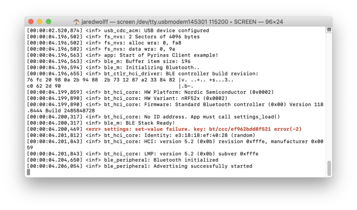
screenI get some nice output:![]()
Things don’t always go as planned though.
The
CONFIG_USB_UART_DTR_WAITdoes lock the processor from executing until the shell session has been opened. The peripheral doesn’t show up otherwise. (not exactly sure why…)With the above being said, the Zephyr stack is fraught with hidden APIs and documentation that is sorely lacking in some areas. Even the features I found above area not in the official Zephyr documention. You should be prepared to hit some potholes as you go along. (I’ve been hitting them for the past few weeks if that gives you any indication!)
Fortunately, Nordic has been leading the charge in making sure that anything related to Nordic devices is as stable as possible.
The nRF9160 Feather Does Some Tricks Too
![]()
The nRF9160 is a fantastic little System in Package. One thing is missing though: Bluetooth. Fortunately, there’s an easy way to add it with Zephyr that works quite well. As you’ll see in the next steps, the picture I pain’t of Zephyr above isn’t all bad.
Looking for the example code
Examples are always a great place to start in Zephyr. The one we can start using almost immediately is the
/nrf/samples/nrf9160/lte_ble_gatewaysample. This sample does everything that someone would want to do in order to connect a nRF9160 to a Bluetooth capable device.You’ll need to have the full
ncs(Nordic’s Connect SDK) setup in order to get to it though. You can learn more about getting setup here. You can also look at my earlier post about it as well.Modifying the Device Tree definition
Taking a look at the
boardsfolder withing the sample you can see that there is an.overlayfile. This helps point which UART interface will be used for the HCI communication. The one for the nRF9160 development kit looks something like this:/ { chosen { zephyr,bt-uart=&uart2; }; }; &uart2 { compatible = "nordic,nrf-uarte"; current-speed = <1000000>; status = "okay"; tx-pin = <18>; rx-pin = <17>; rts-pin = <21>; cts-pin = <19>; };The first part, is about choosing which interface to use. In this case they assigned the
zephyr,bt-uartinterface touart2. They’ve then re-defineduart2below. I say re-defined because every board has a top level.dts(aka a Device Tree) file.Then mapping to the pins that are connected in hardware, they’ve set the speed, what driver to use and more.
The one i’m using for the nRF9160 Feather is not too disimilar.
/ {
	chosen {
		zephyr,bt-uart=&uart2;
	};
};

&uart2 {
	compatible = "nordic,nrf-uarte";
	current-speed = <1000000>;
	status = "okay";
	tx-pin = <24>;
	rx-pin = <23>;
	rts-pin = <29>;
	cts-pin = <30>;
};
You can see i’ve only changed the pin assignments. These are set to match the TX/RX/CTS/RTS pins on the Feather.
Adding to your app configuration
The next thing you’ll have to do, as I alluded to in the first section of this post is to edit your
prj.conffile. If you look at the original, the section related to Bluetooth is the most important:# Enable Bluetooth stack and libraries CONFIG_BT=y CONFIG_BT_H4=y CONFIG_BT_WAIT_NOP=y CONFIG_BT_CENTRAL=y CONFIG_BT_GATT_CLIENT=y CONFIG_BT_GATT_DM=y CONFIG_BT_SCAN=y CONFIG_BT_SCAN_FILTER_ENABLE=y CONFIG_BT_SCAN_UUID_CNT=1 CONFIG_UART_2_NRF_FLOW_CONTROL=y CONFIG_UART_INTERRUPT_DRIVEN=y
As you become familiar with Zephyr, the more likely you’ll be able to recognize which definitions do what. You can also use
west build -t menuconfigand then hit the/button to search for definitions.![]()
Side note: If your program fails to pass the first stage of compilation, you’ll have to fix that before entering the configuration menu.
![]()
Let’s say we want more information about
CONFIG_BT_SCAN. TypeBT_SCANinto the search box.![]()
Then press
enterand then press?. This will give you all the necessary information you need about the option in question.![]()
I’ve used this method numerous times to determine what’s what. Usually the descriptions here are brief so you may not always find what you’re looking for!
The most important defintions that tell Zephyr we’re using HCI UART are:
CONFIG_BT_H4=y
and
CONFIG_UART_2_NRF_FLOW_CONTROL=y
CONFIG_UART_INTERRUPT_DRIVEN=y
Without them compliation would bork or your code would simply not work. I spent a good chunk of time trying to figure out why my setup wasn’t working. I’ll get to that in a second! First though, you’ll have to install the
hci_uartsample to a companion device. In my case i’m using a Particle Xenon.A companion
Next, jump on over to the
/ncs/zephyr/samples/bluetooth/hci_uartexample. We’ll have to do some similar Device Tree finagling here. As of this writing, Xenon is not in theboardsfolder. So we can add aparticle_xenon.overlaywith the Bluetooth to UART interface defined:/* SPDX-License-Identifier: Apache-2.0 */ / { chosen { zephyr,bt-c2h-uart=&uart0; }; }; &uart0 { compatible = "nordic,nrf-uarte"; current-speed = <1000000>; status = "okay"; tx-pin = <8>; rx-pin = <6>; rts-pin = <34>; cts-pin = <33>; };This matches specifically to the complement of the Feather’s TX/RX pins. If you choose to use a different Feather board as the main processor, you can leave this unchanged!
Then matching most of the other
.conffiles, here’s whatparticle_xenon.conflooks like:CONFIG_GPIO=y CONFIG_MAIN_STACK_SIZE=1024 CONFIG_SYSTEM_WORKQUEUE_STACK_SIZE=512 CONFIG_BT_WAIT_NOP=y CONFIG_BT_MAX_CONN=16 CONFIG_BT_TINYCRYPT_ECC=n CONFIG_BT_CTLR_DTM_HCI=y CONFIG_BT_CTLR_ASSERT_HANDLER=y # Use UART0 for HCI CONFIG_UART_0_NRF_FLOW_CONTROL=y
This example uses the Zephyr Link Layer implementation. If you’d like to use the Nordic one, you can add these definitions to
particle_xenon.conf.# Link Layer CONFIG_BT_LL_NRFXLIB_VS_INCLUDE=y CONFIG_BT_LL_NRFXLIB_DEFAULT=y
Remember, a
.conffile is changing application specific definitions. If it’s defined in the board definitions, this file will override it!Then compiling and flashing is as simple as these two commands:
west build -b particle_xenon -p
west flash
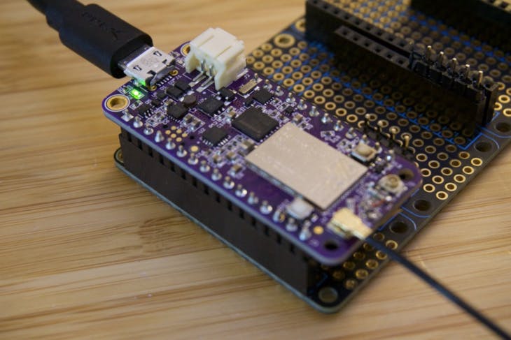
In my case I had connected a nRF52DK to the Xenon in question. As long as there are no other J-Link or programmers it shouldn’t prompt you to choose a programmer. Here’s a picture of the setup:
![]()
This should look farmilar to those who have seem my guides before.
Fire it up!
Programming the nRF9160 Feather in a similar way you are now ready to add the connections. I’ve used a Feather tripler to make the connections easy. I did cut a few traces like the Enable pin since the enable pin on the nRF9160 Feather is active low.
![]()
I also cut the 3.3V that way each board can regulate its own supply. The Xenon is powered by the 5V pin on the nRF9160 Feather.
You can also see the green wire I used to interconnect two pins. This was for controlling reset of the Xenon. This turned out to be critical because without it UART would get stuck! I only figured this out after a very confusing hardware and firmware debug session. I did eventually figured it out. Only after hitting the rest button at the perfectly right time though! You live and learn, right?
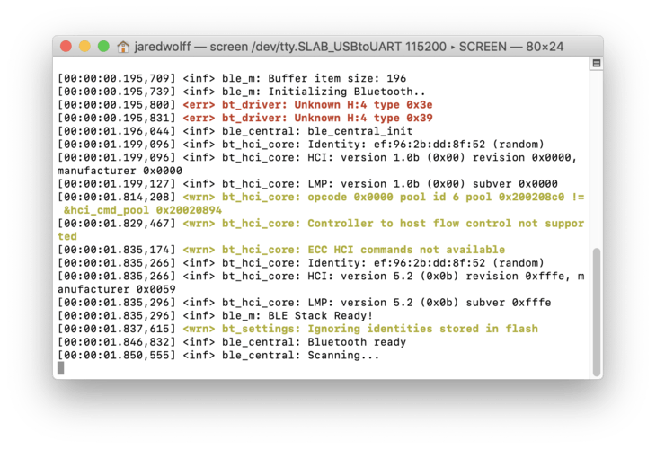
If you’ve done things correctly, you’ll get something nice like this:
![]()
Now that you have one half of the equation done, you can integrate it with almost any device. The
lte_gatrewaysample I mentioned before is used with Nordic’s Thingy52. That’s a great starting point expecially if you have one handy!Another Tip for Debugging Bluetooth
There’s one more tool you may find yourself using during your Zephyr development: the Bluetooth shell.
![]()
Located at
ncs/zephyr/tests/bluetooth/shell, this sample allows you to control a Bluetooth device over a shell session by using a human readable commands. It’s a great sanity check to make sure your device is working in the way you want.I ran this first on a nRF52840 development kit. So my build and flash commands looked like this:
west build -b nrf52840dk_nrf52840 -p
west flash
Once programmed, you can open the session like so:
screen /dev/tty.usbmodem0006838206631 115200
If you’re on Windows, you can use a program like Putty to accomplish the same thing.
Then you can start advertising in normal mode using the following input:
bt init
bt advertising on
Likewise, on a separate device you can scan using:
bt init
bt scan on
You can connect, disconnect, send data and more. To see all of the commands simply type
btin the command prompt.There are little gems like this scattered throughout the Zephyr and Nordic repos. Thanks to some helpful Nordic engineers for the tip on using this tool. Without it, I would have never found it!
More coming soon!
More coming soon especially about nRF9160 Feather developments. Including updates about Proto 3!
![]()
The boards should be at my doorstep this coming week. So i’ll be sure to update everyone on the status of the new active GPS circuit. If that checks out, things may be looking good for launch! Make sure you subscribe to stay up to date on the project!
Originally posted on jaredwolff.com
-
The nRF9160 Feather Connects!
08/01/2020 at 03:42 • 0 commentsThis week, the nRF9160 Feather got some more attention. I even got it to roll over. 😇 To top it all off, my hardware validation list is looking good!
![]()
There’s still tons to do but it’s been a very promising start!
In this post I’ll discuss the state of things and where hardware, firmware and more are going next.
Let’s do this!
What’s in the box?
There’s a ton to Zephyr. Let’s face it, there’s an overwhelming large amount of libraries, sub-libraries, and samples. Nordic’s Connect SDK requires several different repositories to make things work.
Here’s what a typical top level directory looks like:
- bootloader - the MCUboot bootloader used for the nRF9160 (and other boards)
- mbedtls - a library imported by the SDK. Used for encrypting/decrypting data
- modules - modularized external libraries (littlefs, etc)
- nrf - most Nordic samples live here
- nrfxlib - the main set of Nordic based libraries and code.
- test - testing infrastructure
- zephyr - the main OS libraries, board definitions and more samples
The biggest difference between the Nordic’s standard and Connect SDK is the sample code. For the standard SDK, they’re all located in one place. Whereas for the NRF Connect SDK, they’re scattered throughout every repository involved. For instance, the basic blinky example is in
zephyr/samples/basic/blinky. The complex Nordic specific samples are in the/nrf/samplesdirectory.Why is this?
The folks behind Zephyr were smart and make their samples generic. Meaning that you can run them on any piece of hardware. The only limitation is to make sure you have a hardware definition for your board!
An important sample
The most important sample that I had found in the
nrfdirectory was theat_clientfirmware. (underncs/nrf/samples/nrf9160/at_client)Along with nRF Connect (for Desktop), it makes a potent combo for debugging. Plus it’s a great tool for surveying your current area for M1/NB1 service.For me, it was a great tool to make sure that the nRF9160 Feather was working a-ok. The only change I had to make was to the
prj.conffile. I added a section that allows you to set the PDP context (i.e. set the APN)# Set the PDP context CONFIG_LTE_LINK_CONTROL=y CONFIG_LTE_PDP_CMD=y CONFIG_LTE_PDP_CONTEXT="0,\"IP\",\"hologram\""
In my case, I was testing holigram. Their APN is also named
holigram. For other providers, like Twilio, theirs is different. Twillio’s “Super” SIM usessuper. Their standard wireless service iswireless.twilio.com. In some cases, like AT&T and Verizon, you do not have to set the APN. It’s set for you by the modem firmware.Building and flashing the firmware is a breeze. Here’s what it looked like on my end:
west build -b circuitdojo_feather_nrf9160_ns
west flash && nrfjprog -r
Then opening up the serial console, as I talked about previously and typing in
AT. You should get anOKback. Disconnect from the terminal though, the LTE Link Monitor will need it!Nordic’s LTE Link Monitor
You use the Link Monitor to connect directly to the
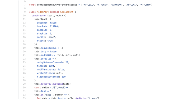
at_clientfirmware. You can either enter AT codes manually or have the Link Monitor run through them. As of this writing though, the LTE Monitor does not support connections that do not have flow control!Oh but I didn’t know that going into it. After a few hours of debugging, and posting to Devzone I found my answer. The
ModemPortlibrary, used in LTE Link Monitor, initializes withrtsctssupport always on.Not great for non-flow control boards, right?
![]()
Fortunately, rebuilding with
rstctstofalsefixed things. That wasn’t a piece of cake though.There was yet another set of problemsthat turned me intro a giant stress ball. Fortunately changing some of the dependencies in
package.jsonseemed to fix it!After that, I was off to the races!
Here’s what things look like when you first make a connection.
![]()
If you haven’t already, select your serial port in the top left. If it’s not showing up make sure that you un-check Auto device/port filter. That’s located in the bottom right. (See the above picture). In my case, it’s called
/dev/tty.SLAB_USBtoUART.![]()
Once you select your port, it should start streaming commands. Pay attention to the right side of the screen. When the Link Monitor receives updates, it reflects that in the status area.
![]()
You should see a ton of activity. If not make sure you enable Automatic Requests (bottom right side checkbox, checked by default). If you are using flow control, then UART will be green as well. If not, it will remain red.
Imagine for a second, the happy dance I did after a successful connection. This was only after several unsuccessful attempts using other cards.
When you’re ready to start testing with any nRF9160 based board, (including the nRF9160 Feather), the LTE Link Monitor is your friend. For more information about how to use, you can download the LTE Link Monitor guide here.
SIM testing update
As you can imagine, testing hardware and firmware is one thing. Testing wireless services is a completely separate prospect! I have some notes in the table below on the services and SIMs that i’ve tested thus far. Your mileage may vary, especially if you’re not within the USA.
![]()
Overall, the results were frustrating. This is most likely due to the fact that either
- There is no service in my area
- Or, the service is blocking your device from connecting because of an invalid IMEI.
In either case, i’ll be making more progress in the weeks to come!
-
Getting Zephyr Running on the nRF9160 Feather
08/01/2020 at 03:41 • 0 commentsIn this post, I’ll be outlining my first experiences with Zephyr and nRF Connect SDK. If you’re not familiar, Zephyr is an up and coming RTOS for embedded devices. It brings things like threads to tiny little processors so that your real time tasks can be handled efficiently!
I’ll run though the setup all the way to programming the device with some somewhat useful code. If you’ve been thinking about playing with Zephyr then this post is a great first step. So join me and let’s get rolling!
What’s involved?
In order to directly communicate and program the nRF9160 Feather you’ll need some ingredients:
- An Arm Cortex Tag Connect connector. I’ve been using the ‘No Legs’ variety for a while now with great success. (The nRF9160 Feather onlysupports the ‘No Legs’ version)
- An Arm Cortex Tag Connect connector. I’ve been using the ‘No Legs’ variety for a while now with great success. (The nRF9160 Feather onlysupports the ‘No Legs’ version)
A Nordic nRF53-PDK or nRF9160-DK. I recommend the nRF53-PDK as it’s significantly cheaper! Plus, if you’re only using it as a programmer you don’t need all the extra functionality the nRF9160 board has.
![]()
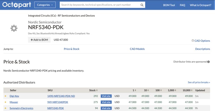
Here’s a list of all the places you can get one from.
Digikey, Mouser and Symmetry are good choices if you’re in the USA. Digikey hands down will ship the fastest but they’re usually the most expensive!
![]()
I ordered mine from Symmetry and it took about a week to arrive via First Class Mail.
- A Nordic nRF53-PDK or nRF9160-DK. I recommend the nRF53-PDK as it’s significantly cheaper! Plus, if you’re only using it as a programmer you don’t need all the extra functionality the nRF9160 board has. Here’s a list of all the places you can get one from. Digikey, Mouser and Symmetry are good choices if you’re in the USA. Digikey hands down will ship the fastest but they’re usually the most expensive! I ordered mine from Symmetry and it took about a week to arrive via First Class Mail.
A nRF9160 Board! As you may or may not know, the nRF9160 Feather is happening in collaboration with GroupGets and Hackster. I can’t wait to get them in your hands! You can sign up for the mailing list so you know when they’re available.
- A nRF9160 Board! As you may or may not know, the nRF9160 Feather is happening in collaboration with GroupGets and Hackster. I can’t wait to get them in your hands! You can sign up for the mailing list so you know when they’re available.
Now, let’s get to the fun stuff.
Hooking things up
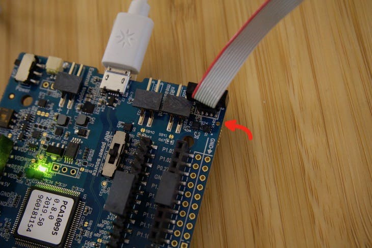
Using the Debug connector on the nRF53-PDK we can make a programming connection to the nRF9160 Featherwing. Simply connect the rectangular Cortex-M style connector to one end. Then, connect the spring finger portion to the other side. Remember you can do this with any nRF9160 or nRF53 based board using the nRF53-PDK. Not just the nRF9160 Feather. 😉
Here are a couple of close up shots:
![]()
![]()
![]()
There’s one important thing to know about any nRF Development Kit. I highly recommend you jump your debug connector power so it’s permanently “on”. This forces the debugger to think an external devices is permanently connected.
On this board the jumper is SB47. I’ve highlighted it below:
![]()
If you still plan on using the onboard chip, then don’t short this jumper! Considering i’m using mine only as a programmer, so I bridged this jumper. (the picture above was before I jumped it with my trusty soldering iron)
After hooking things up, It’s time to do a quick smoke test. Running
nrfjprog -rin a terminal should show this result:$ nrfjprog -r Applying system reset. Run.
Success!
I’ve been using Nordic stuff for a while so I already had
nrfjproginstalled. More info aboutnrfjprogand other Nordic Command Line tools is here.Setting up the environment
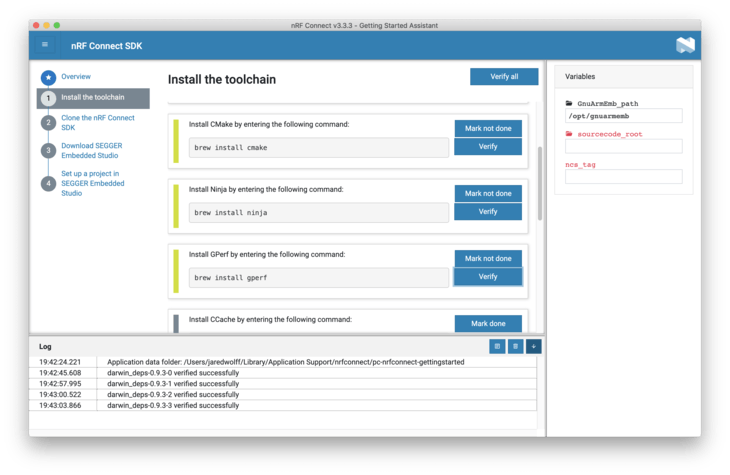
To get started, Nordic has documentation located here. I’m on OSX so Nordic recommends to use the “Getting Started Assistant” in nRF Connect for Desktop.
The advantage of the Getting Started Assistant is that it’s more interactive. You’ll likely need it since there are a ton of 3rd party tools to install. So the original Nordic SDK still wins in that department for sure!
![]()
Slowly making my way through the steps..
![]()
Most of it is painless. In many cases if you’re an active firmware dev you’ll have these tools installed already.
Installing the IDE (Don’t hurt your eyes)
As a getting started step, Nordic states that Segger Embedded Studio is “required”. I’m not a big fan of these types of IDEs. It locks you into yet another development environment you need to learn etc. I’m big on Visual Studio Code and use it for all the coding I do whether it’s C/C++/Rust/Go/Javascript etc.
You can download from the link they provide in the Getting Started Assistant:
![]()
Once downloaded, you can unzip and then copy arm_segger_embedded_studio_v452_macos_x64_nordic (or similar) to your Applications folder. (Or wherever you want!)
Then navigate to it and and run SEGGER Embedded Studio for Arm. The instructions have some more info about how to handle the warning below. As long as you follow the instructions you’ll be golden!
![]()
After navigating the interface though, all I wanted to do was barf on my keyboard. The interface is atrocious. (Sorry Segger/Arm!) I’ll be focusing on using Visual Code and the command line for the rest of this tutorial. Nordic only supports Segger so don’t expect any help if you go outside the box!
Working with Visual Studio Code
First of all, there is a way to build SDK examples using the command line. I almost always have a terminal window open and ready for most projects. So this was not new!
The jist of it is the following:
From your
ncsdirectory (you set up earlier of course!), change to the example you want to run.cd zephyr/samples/basic/blinky
Then run the build using
west.westis like a wrapper for a wrapper for a wrapper. It makes building code for Zephyr easy. Despite being another tool that will invariably break, i’m finding it’s makes things simple.In this case i’m compiling for the nRF9160 Development Kit using the
nrf9160dk_nrf9160board definition. (i.e. generating binaries specifically for the nRF9160 DK)west build -b nrf9160dk_nrf9160
If you get an error about your Python version, make sure your path is set correctly. I had to update my
.bash_profilewith these lines:# Zephyr related export ZEPHYR_TOOLCHAIN_VARIANT=gnuarmemb export GNUARMEMB_TOOLCHAIN_PATH="~/gcc-arm-none-eabi-8-2019-q3-update" # Python related export PATH="/usr/local/opt/python/libexec/bin:$PATH"
Note: if you’re on OSX Catalina you’ll have to set up your
.zshrcand .zprofileinstead. Remember to open a new terminal window once you’ve done this!This was nice and all but I didn’t want to compile for the development kit. I wanted to compile for my board! Fortunately there was some documentation on porting over a custom board.
Side note: once 100% tested, i’ll put in a pull request to the Zephyr repo for the board files. That way everyone can use the board immediately with examples!
So let’s get an LED working!
cd ncs/zephyr/samples/basic/blinky
west build -b circuitdojo_feather_nrf9160 --pristine
The
--pristineargument will run acleanon all the appropriate files. Otherwise it assumes you’re working with the configuration as before. Subsequent calls you only need to runwest buildSide note: the board definition for the nRF9160 Feather will be called
circuitdojo_feather_nrf9160. I’ve changed it here as I was testing the board itself rather than the dev kit. 😎Flashing to a board is as simple as running
west flash. You can also runwest flash --eraseif you want to erase the full contents of flash. Running either command will rebuild the code if there are any changes.💡Remember:
west flashutilizes the debugger that’s attached to your computer and your board. Without a nRF DK attached to your board you won’t be able to program. If your board has a serial enabled bootloader, you’ll be able to use the built in USB port on the nRF9160. More on that in a sec!After running you may notice that … nothing is happening! That’s because the processor is still being held in reset. Running
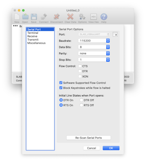
nrfjprog -rwill fix this and begin code execution. (This requires you havenrfjproginstalled. Info on that here.)The nRF9160 Feather also comes with a USB to Serial chip by Silicon Labs. On OSX it shows up as SLAB_USBtoUART. (You may need to install drivers for your operating system.)
Here’s an example of what it looks like using Cool Term.
![]()
After running
nrfjprog -ri also checked to make sure that there was UART output.![]()
Success a blinking LED and a boot message coming over UART to the Silicon Labs chip!
Using the bootloader
One of the more important aspects of any embedded development process is streamlining the uploading of new code to devices. Zephyr makes this easy with MCUboot.
You can find a very basic version of an example with a bootloader within the bootloader repo. First navigate to
ncs/bootloader/mcuboot/samples/zephyr/hello-world. Then run the following commands:west build -b circuitdojo_feather_nrf9160 --pristine west flash nrfjprog -r
If you want to compile for another board make sure you change
circuitdojo_feather_nrf9160to your board variant name.Once flashed, here’s the output from CoolTerm:
![]()
Nice! Remember your programmer is still connected for this step. Without it you won’t be able to program. That will change momentarily though…
One file that is critical to your Zephyr based projects is
prj.confIt’s very similar to the idea ofsdk_config.hbut much nicer on the eyes. It’s also very similar to how FreeRTS does their configuration as well.# Print a banner on the UART on startup. CONFIG_BOOT_BANNER=y # Enable console and printk() CONFIG_PRINTK=y CONFIG_STDOUT_CONSOLE=y # Enable Zephyr application to be booted by MCUboot CONFIG_BOOTLOADER_MCUBOOT=y
The most important line is the one with
CONFIG_BOOTLOADER_MCUBOOT. This enables the bootloader and shifts your code around automagically. There’s no need to modify linker files. No need to dig into the code and figure out what address has what. All I can say is that it’s very convent!Testing out loading over USB
Next step is actually getting the bootloader to accept updates from USB. This part, conveniently, is built into the board definitions. So you never have to worry about it.
In the
ncs/bootloader/mcuboot/boot/zephyr/boardsfolder, I created a new file specific to the nRF9160 Feather. Inside I add a few definitions that will enable loading via USB-to-Serial. You will not have to set these yourself.# Disable Zephyr console CONFIG_CONSOLE=n CONFIG_CONSOLE_HANDLER=n CONFIG_UART_CONSOLE=n # MCUBoot settings CONFIG_BOOT_MAX_IMG_SECTORS=256 # MCUboot serial recovery CONFIG_MCUBOOT_SERIAL=y CONFIG_BOOT_SERIAL_DETECT_PORT="GPIO_0" CONFIG_BOOT_SERIAL_DETECT_PIN=12 CONFIG_BOOT_SERIAL_DETECT_PIN_VAL=0
If you do a
west buildback in the example directory, you’re code will update to add that feature. (Again, i’m impressed!) Then usewest flashto flash your bootloader + application combo to your device.I was a little confused where to go here so this took a while to reach. I eventually stumbled on this post on Devzone which outlined what needed to be done. Nordic also wrote up a tutorial on how to update the Thingy91 over USB. That post is here.
The most important thing I got out of those posts? Turns out we need one more utility to make everything happen:
mcumgrTo install you’ll need Go version 1.7 or greater. If you don’t have it installed, run
brew install go. For other platforms you’l have to install according to the information here.Now, run
go getgithub.com/apache/mynewt-mcumgr-cli/mcumgrfrom any terminal. This will install and allow you to runmcumgrwhich will do the transferring for us!Ok, so now we have a bootloader + app on the board. Now what?
We need to put the board into DFU mode.
In the
MCUboot serial recoverysection of the configuration file, we can also define a pin to enable DFU mode on a cold start. So in order to make DFU mode go you can hold the MODE button and tap the reset button on the nRF9160. DFU mode is nearly instant and can accept an update within a second or two.(Ideally in the future you won’t have to do this, but for now this is the workflow!)
As your remember from before we loaded up first with a “Hello World” type message. Now, I mashed together the Blinky example with that one. See the transformation below:
/* * Copyright (c) 2017 Linaro, Ltd. * * SPDX-License-Identifier: Apache-2.0 */

#include <zephyr.h>
#include <sys/printk.h>

void main(void)
{
	printk("Hello World from %s on %s!\n",
	       MCUBOOT_HELLO_WORLD_FROM, CONFIG_BOARD);
}
To:
/* * Copyright (c) 2017 Linaro, Ltd. * * SPDX-License-Identifier: Apache-2.0 */

#include <zephyr.h>
#include <sys/printk.h>

#include <zephyr.h>
#include <device.h>
#include <devicetree.h>
#include <drivers/gpio.h>

/* 1000 msec = 1 sec */
#define SLEEP_TIME_MS 1000

/* The devicetree node identifier for the "led0" alias. */
#define LED0_NODE DT_ALIAS(led0)

#if DT_HAS_NODE(LED0_NODE)
#define LED0 DT_GPIO_LABEL(LED0_NODE, gpios)
#define PIN DT_GPIO_PIN(LED0_NODE, gpios)
#if DT_PHA_HAS_CELL(LED0_NODE, gpios, flags)
#define FLAGS DT_GPIO_FLAGS(LED0_NODE, gpios)
#endif
#else
/* A build error here means your board isn't set up to blink an LED. */
#error "Unsupported board: led0 devicetree alias is not defined"
#define LED0 ""
#define PIN 0
#endif

#ifndef FLAGS
#define FLAGS 0
#endif

void main(void)
{
	printk("Hello World from %s on %s!\n",
				 MCUBOOT_HELLO_WORLD_FROM, CONFIG_BOARD);

	struct device *dev;
	bool led_is_on = true;
	int ret;

	dev = device_get_binding(LED0);
	if (dev == NULL)
	{
		return;
	}

	ret = gpio_pin_configure(dev, PIN, GPIO_OUTPUT_ACTIVE | FLAGS);
	if (ret < 0)
	{
		return;
	}

	while (1)
	{
		gpio_pin_set(dev, PIN, (int)led_is_on);
		led_is_on = !led_is_on;
		k_msleep(SLEEP_TIME_MS);
	}
}
(I’m combining the Zephyr
blinkyexample with the MCUboothello-worldexample.)Then to update over serial you can run
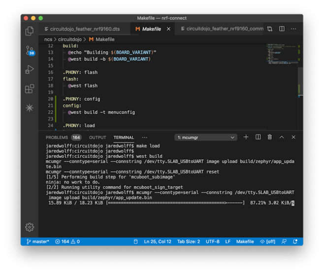
mcumgrwith similar arguments.west build mcumgr --conntype=serial --connstring /dev/tty.SLAB_USBtoUART image upload build/zephyr/app_update.bin mcumgr --conntype=serial --connstring /dev/tty.SLAB_USBtoUART reset
Remember to replace
/dev/tty.SLAB_USBtoUARTwith your serial port.build/zephyr/app_update.binshould stay the same.Shortly after I got a blinking LED and a Hello World message over serial (after I reconnected using Cool Term). Now we’re cooking with gas!
Testing Peripherals
One thing I like to do is make sure that all peripherals are working as expected. Some things can be tested without firmware (like the charger). Some require some firmware intervention. For example, setting up I2C + the RTC looks something like this in Zephyr:
/*
	 * Set up I2C
	 */
	struct device *i2c_dev;
	i2c_dev = device_get_binding("I2C_2");
	if (!i2c_dev)
	{
		printk("I2C: Device driver not found.\n");
		return;
	}

	// Configuration
	u32_t i2c_cfg = I2C_SPEED_SET(I2C_SPEED_STANDARD) | I2C_MODE_MASTER;
	if (i2c_configure(i2c_dev, i2c_cfg))
	{
		printk("I2C: config failed\n");
		return;
	}

	// Write a test command and check for ACK
	uint8_t buf[] = {0};
	ret = i2c_write(i2c_dev, buf, sizeof(buf), PCF8506_I2C_ADDR);

	if (ret < 0)
	{
		printk("I2C: Unable to communicate with RTC.\n");
		return;
	}
In order to use I2C, make sure that this is in your
prj.conf:CONFIG_I2C=y CONFIG_I2C_2=y
The nRF9160 uses “I2C2” peripheral as this is default for the development kit. You should keep this the same for now.
I ran another
west buildand loaded the app over usingmcumgr.![]()
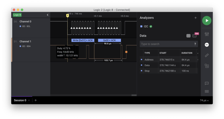
Hooking up my Saleae, I got a nice result after loading and resetting the device:
![]()
For some reason 0 byte transfers don’t work. But that’s ok. Sending some dummy data works just as well!
Next steps!
I have an ever growing list of bringup tests I want to run before making the nRF9160 official. I’m taking no shortcuts here to make sure these boards are a stable foundation you can base your own designs on.
![]()
I’m also working on something special related to LTE which will make it much easier for you to get started with nRF9160. More on firmware, hardware and more in coming posts. Make sure you’re subscribed to the list to stay up to date on progress.
Until next time!
-
Designing the nRF9160 Feather
05/20/2020 at 19:03 • 0 commentsWhenever I design a board, I optimize as much as possible. Layer count, part count and even part location can play a big role in how much assemblies cost later down the road. In this article, I go into depth about the decisions I made when designing the nRF9160 Feather. Let’s do this thing!
The Essentials
The first part of the process was determining what stays and what goes. In my case, as this is a traditional Feather, the design needed some functionality. Things like:
- A built in Li-Poly charger
- USB for charging and USB-to-UART transfer
- Programming connections for SWD/JTAG
- External flash storage. (The nRF9160 has 1MB of flash but more external non-partitioned space is always good!)
- A way to get the device into super low power.
- And, of course, the capability to support the nRF91 + antenna connections.
This by no means is a short list! Each feature has its own nuance which is important when trying to mash them all onto a 22.86x50.8mm board.
CAD of Choice
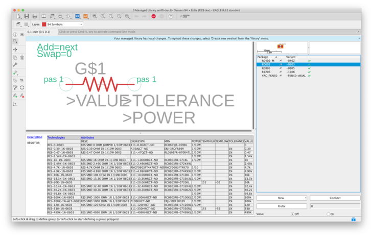
After using many CAD packages (and owning some) I go back to Eagle every time. I also use it to track my library and my parts. Every time I add a part, I enter the part data like MPN, Description and more. That makes exports into a shopping cart or even into a MRP/PLM tooleasy peasy.
![images/Screen_Shot_2020-05-19_at_4.17.33_PM.png]()
I’ve described my methodology in the past. You can check it out here.
Stack It Up
Placing parts is the first step. It’s a helpful guide to what will fit where. I actually started with a 2 layer board and then upgraded to a 4 layer later on due to the increased density.
In comparison with the Air Quality Wing, there’s little room on the top layer! It’s one of the more complex boards i’ve designed from concept to fab. In the past i’ve used layout services but doing it myself was going to be cheaper and faster!
![images/Untitled_design-6.png]()
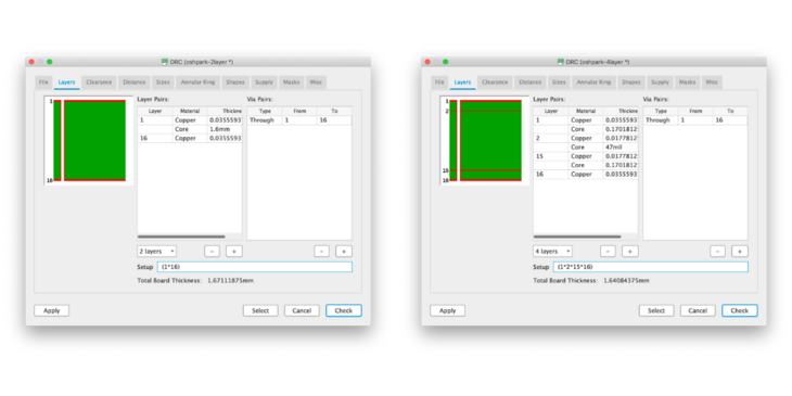
Thanks to OSH Park’s fab design constraints, I didn’t have to think much about the stack up. The important thing is that you’ll want to use what ever your board house deems “standard”. Don’t thinking about it too much though, or you may get lost in the list of what they can do. (OSH Park has a similar list but it’s much more concise. We’re not building rockets here.. or are we?)
Here’s what a standard stack up looks like for both OSH Parks 4 and 2 layer .ulp files. You can get them here if you’re interested in a good starting point for your own designs!
![images/Stackup_Side_by_Side.png]()
Placement and Constraints
When placing a new board, you always want to place parts as recommended by the various ICs you chose. i.e. placing a bypass cap as far away from the chip you’re using will not do much at all!
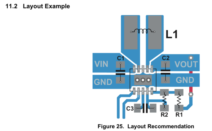
For example, TI recommends you keep the bypass caps and inductor as close to the DC/DC as possible. Here’s a screenshot of their layout recommendations in the datasheet:
![images/Screen_Shot_2020-05-20_at_12.48.21_PM.png]()
Source: TPS63031 datasheet
You can see that the input and output copper is fairly chunky. I’ve also drilled a ton of vias which decreases the resistance in layer transitions.
![images/Untitled.png]()
I’m a polygon maniac so I use it for all shapes that I can’t fix with a simple trace. Additionally, I will almost always turn off thermals for these shapes. Otherwise you lose most of the copper involved. There are some cases where you will have to tweak this setting though! This is true especially if you attempt soldering a pin thats tied to a large chunk of copper (i.e. a hefty ground plane). In that case, if you don’t use thermals, you may end up with cold solder joints!
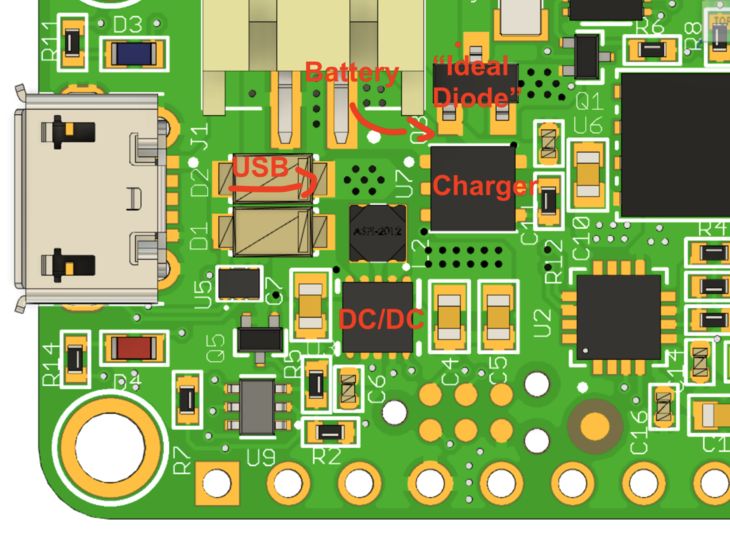
You can also see that i’ve kept most of the power related parts clustered in the same area.
![images/Screen_Shot_2020-05-20_at_12.33.25_PM.png]()
This decreases any parasitic resistance between all the important power related parts. Despite being very close, many of the power traces transition to an inside layer. Let’s take a look.
Setting Up the Layers
![images/Screen_Shot_2020-05-19_at_5.25.23_PM.png]()
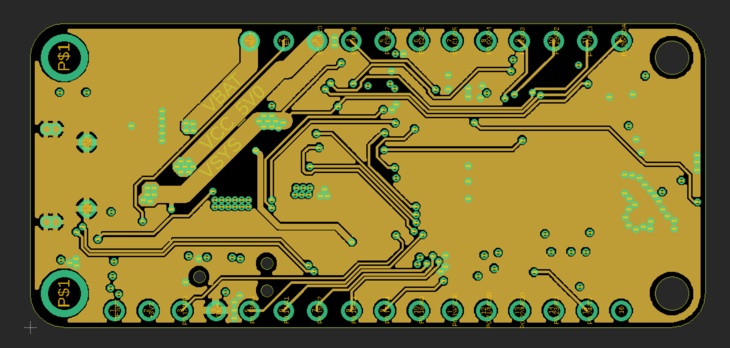
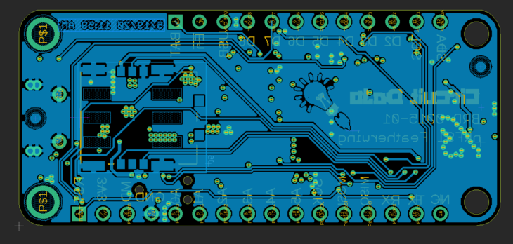
In Layer 2 I’ve routed some of the power signals from the top side through this layer. You can see there’s battery, 5V to the 5V pin and VSYS which is the combined input to the DC/DC. I almost always route these chunky power traces before I do the smaller stuff. They’re much more important and should have as a direct route as possible. (this goes back to keeping trace resistance low which is 👍 for power delivery)
You can also see that i’ve done routing of many other miscellaneous signals on this layer. I used the convention of connecting the outside through holes to this layer. This allowed for a more direct connection to pins on the nRF91.
Finally, if you look closely there’s a set of traces coupled together. These happen to be the USB D+/D- signals.
![images/Screen_Shot_2020-05-19_at_5.30.54_PM.png]()
This board is not doing anything crazy high speed so routing from the top to the next layer down was ok in my book. In general though, especially for differential signals, avoid the layer transitions!
Similarly for the top and bottom layer, i’ve used a copper fill connected to ground. That way it’s easier to make a ground connection. This also helps considering Layer 2 is all chopped up by the traces, vias and chunky power traces!
![images/Screen_Shot_2020-05-19_at_5.57.04_PM.png]()
On the bottom layer there is only one surface mount component. If I had the ability to, I would have put it on the top side. Unfortunately the SIM holder is way too bulky!
If it was a possibility that would have saved about $100+ in stencil cost. As you can imagine you can save some costs on SMT assembly as well! For this side, i’ll skip Automated Optical testing since there’s only one component. Hard to get that one wrong!
![Bottom Side]()
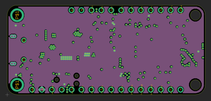
As for the other inner layer, it’s simple a layer for 3.3V only. If a part needs 3.3V, drill to the layer below for power. There’s no futzing with power traces. It’s clean and makes signal routing efficient!
![images/Screen_Shot_2020-05-19_at_6.02.35_PM.png]()
The only thing to watch out for is all the non-connected vias turning the layer into swiss cheese. Imagine if I had 2x the vias in the above capture. That would cause the layer to not be as thick and contiguous. This could lead wreak havoc on your circuits. Fortunately this design is simple enough where that is not a huge concern!
Don’t short power to ground.
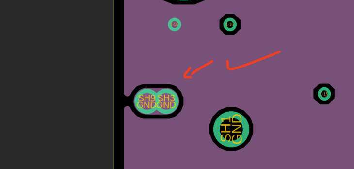
As I had mentioned in my previous post, I ran into some issues where I did not define my slots correctly. Fortunately, the only part that was using slots was the USB connector. If you zoom in on the 3V3 layer you can see now it’s fully isolated. That way this problem won’t happen again!
![images/Screen_Shot_2020-05-20_at_12.10.58_PM.png]()
To construct a slot, use the Milling layer (Layer 46 in Eagle) plus some through hole “pins”. OSH Park merges these all together so there no need to worry about overlapping drill passes.
Shutting Things Down
One of the more important things about the design is the ability for the board to turn off. That’s right, completely off.
My thinking went to two options of handling this power down state:
- Turn the power supply completely off. Only power supplied to an “always on” part acting as a supervisor.
- Or, turn off the switching power supply and run most of the circuitry off of a parallel LDO. The circuitry would then be run in a low power/standby state.
The thought experiment lasted a while. Even up until I was about to send Proto2 to fabrication! I decided to go with option 1 over option two because it will draw the least amount of power when off. Plus it’s the most simple! The second option required a significant amount of tweaking and hacking.
On a comparison level I was looking at something like 1-2µA in option 1 versus about 8-10µA in option 2. I’ve yet to measure and test but these principles have been time tested by others that have come before me.
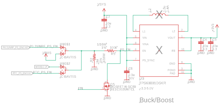
Here’s what the DC/DC circuitry looks like. As you can see there are multiple parallel diodes providing a signal to the EN pin. All these individual sources can keep the nRF9160 Feather powered.
![images/Screen_Shot_2020-05-20_at_12.24.25_PM.png]()
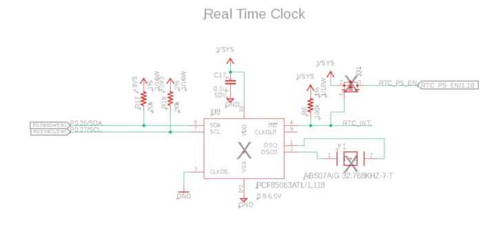
One of those sources is an RTC (Real Time Clock). This chip draws less than 1µA and uses a 32kHz crystal to generate accurate time. It has some timer and alarm features which are perfect for waking up the DC/DC at a programmed timeframe.
![images/Screen_Shot_2020-05-20_at_12.24.57_PM.png]()
Additionally, we can use the GPIO on the nRF91 to keep the power supply on. Once it’s ready to sleep/shutdown it releases that pin.
For field deployments, the low power state is more important than the powered state. That’s because you spend most of your time in this state. A difference of a few µA can lead to a difference of years in operation. And that’s the problem i’ve tackled here in the nRF9160 design.
RF Circuitry
The RF circuitry for this board was not straight forward. There are still some open questions about how it would perform. Since I’m located in the USA, I will only be able to test an LTE based solution. (Though the nRF9160-SICA is able to do both!)
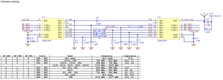
![images/Screen_Shot_2020-05-20_at_2.04.20_PM.png]()
From Nordic’s Thingy91 Schematic
If you want to see something cool, take a look at Nordic’s Thingy91 reference design. You can see that they multiplexed the matching circuitry for each band. There are pins on the nRF9160 which are 100% dedicated for driving these multiplexers. Unfortunately, as you can see below, there’s little room for that!
![images/Screen_Shot_2020-05-20_at_12.38.30_PM.png]()
The most important thing here was to include GPS along with celluar. Why have a nRF9160 board, which has GPS, but no way to use it? Silly no?
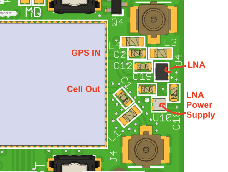
The GPS signal uses a separate LNA + Power Supply for amplification stage. This seems to be common practice across Nordic’s reference designs. Here’s what mine ended up looking like:
![images/Screen_Shot_2020-05-20_at_2.07.25_PM.png]()
The cool thing was discovering that I could use COEX0 pin to drive the power and enable for the LNA. I’ll test Proto2 in the coming weeks. I’ll be sure to share my findings with you.
Open Source
Anyway that’s the current state of the nRF9160 Feather! Proto2 is well on its way. With that some more debugging and testing!
I know you must be wondering, can I get my hands on this source? The answer is: soon! I’m excited to say that the design will be fully open source when it launches with Hackster and GroupGets. As you can tell, there’s more to do but i’m excited to get it in your hands soon! If you’d like to be one of the first to know about availability, sign up for the mailing list here.
Next Post
Next weeks post will be detailing setup of Nordic’s nRF Connect SDK. So stay tuned for that!
-
Prototype to Launch
05/11/2020 at 21:26 • 0 commentsPopulating (or stuffing) circuit boards can be a messy process. It's fraught with high heat, chemicals and teeny tiny parts. What could go wrong? 😬
In this post, you’re learn how I assembled the first prototypes of the nRF9160 Feather. It's my first full on collaboration with Hackster Launch and GroupGets. Which is quite exciting!
This post is lengthy but you’ll get all the nitty gritty details of the build.
Prepare for Greatness
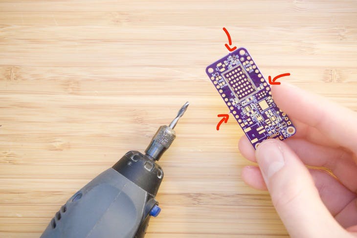
If you order boards from OSH Park, you’ll notice that your boards come with sharp barbs usually on every side. These are leftover from panelization and need to be removed. My tool of choice for this is to use a 1/8” 4-flute end mill and my Dremel. You can see in the picture below the “barbs” i’m talking about.
![]()
Though it does push some dust around, its by far the easiest methods beyond putting it in a CNC de-panelizing machine. And oh, if you’re doing this yourself, make sure you suck away the debris. You don’t want to breathe that stuff in!
![]()
After some careful grinding it should look more like this:
![]()
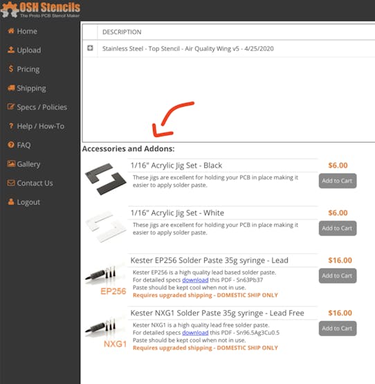
The main reason we do this at all is because of the next step: dispensing paste. This allows you to secure the board so it won’t move when you’re trying to carefully place paste in the right place. In my case, i’ve used acrylic pieces which are very similar to the ones that OSH Stencils sells.
![]()
If you don’t have access to a laser cutter, this is your best bet!
Next you’ll need some masking tape and the boards you’re working with. Lay them flat on the table and push the ends together.
![]()
Then use your handy dandy masking tape to hold the fixture down so it doesn’t move.
![]()
One thing that I noticed with the nRF9160 Feather board is that the Z-height is slightly smaller than a standard 2-layer from OSH Park. (This board is 4-layers) I simply removed the protective coating on the acrylic and it helped move the board just above the acrylic. 👍
I then placed the stencil over the board. Aligning all of the solder mask openings can be tricky. I always use opposing corners to make sure i’m “square”. A good rule of thumb is if you see all gold color coming through the stencil holes, you’re good! I’ve screwed this part up many times so I recommend take your time here.
![]()
![]()
At this point you should be ready to dispense paste. I’ve cut one of OSH Stencil’s cards into a smaller spatula. That way I can retrieve solder from the paste jar. I’m currently using this paste for this board.
One thing that I did not realize about the paste when I bought it is the paste type. We’re not talking about lead free or leaded. We’re talking about how big the solder balls inside the paste are. The bigger they are, the larger openings you need in your stencil. A big thanks to Matt, one of my mailing list subscribers, for pointing out this important detail!
Fortunately, this solder paste is Type 4 which means it will certainly work for this prototype board!
I dabbed some of the paste on the stencil and used the other half of the OSH Park card to squeegee it across.
![]()
The squeegee process takes some practice. I’ve yet to master it. Thankfully there are machines that do this much better!
![]()
This is also the main reason why you want to secure your stencil well before applying paste. Otherwise your stencil will shift and you’ll have to wipe and redo. No one likes to wipe and redo!
Once complete, i’ll undo the tape on one side. Then, I’ll lift it over and get it out of the way. Slow and with control though!
![]()
If you look closely the paste closest to the USB connecter got a bit.. messy. That wasn’t my concern though, my concern was the nRF9160 module. Those, at the time, appeared to look ok!
![]()
Here’s a close up using one eyepiece on my microscope.
![]()
Not bad. A little off but otherwise worth a try. In retrospect I should have seen warning signs that this would not work but we’ll get into that later.
Assemble It
So we have solder paste on a board, now what?
Assemble all the bits!
I’ll typically remove the board carefully from the acrylic jig. Then i’ll start placing components where they need to go. I’ve primarily used tweezers but i’m also experimenting with a suction mechanism.
![]()
While my hot air machine has this functionality, i’m in the process of building my own. (It doesn’t have the features like a nice foot switch. Plus it doesn’t shut off the hot air when pick-and-placing.)
One thing you should do if you do build your own boards: print out a black and white copy of your schematic. This will help you figure out what parts go where. Also, if you didn’t notice earlier, every part on the nRF9160 Feather has a reference designator somewhere near the component. That way you don’t have to keep referencing your board files during the assembly process.
Let It Flow
So, after carefully placing every single component it was time to flow some solder. Yup, it’s time to apply heat!
![]()
About a year ago I read about how other folks bake their boards. Sometimes they use toaster ovens. Some buy cheap Chinese ovens designed for the job. In my case, a used Oster skillet was all I wanted.
So for $15, I picked one up at the local Goodwill and i’ve never looked back since.
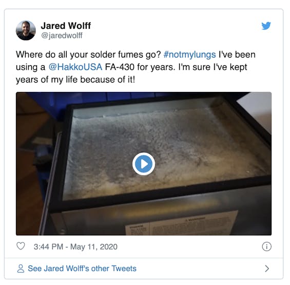
As you can see in the above picture, I position my boards over the coil and crank it up all the way. You also see that I use my fume extractor for filtering the air. Without that guy i’d probably have all types of cancer. So thanks Hakko.
Side note, here’s what the inside of my FA-430 looks like:
![]()
After checking that all of the solder had wetted I also checked the module. Simply taking a pair of tweezers and nudging the module is a good sanity check. That way you know if the solder underneath is hot enough. If it moves and then bounces back when you move the tweezers away, you’re done. If it, A) doesn’t move or B) moves but doesn’t go back your board needs more time in the heat. This especially applies to parts with pins underneath that you normally wouldn’t be able to see.
After removal it’s time for inspection! Unfortunately, I found a few issues:
![]()
I’m not quite sure how this one happened but it was likely due to mishandling. You can also see that the giant 0805 cap had tombstoned. So much for being careful! Fortunately, these are easy fixes. The next problem though, is not an easy fix:
![]()
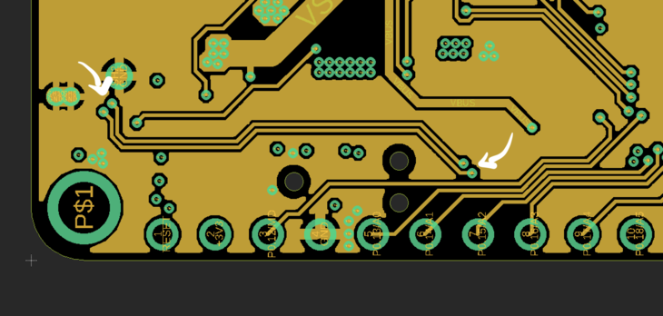
Those are the tiny 0.3mm x 0.3mm pads underneath toward the side of the nRF9160 module. What’s wrong? They’re shorted! Crap.
As I looked around at each edge of the module, I noticed a similar pattern. Most of the pins were shorted to each other.
Damnit.
The Debugging Begins
So, I held the board in place with a 3rd hand and removed the module. This requires two things:
- Patience
- Large tweezers
![]()
Using the hot air at about 370°C on a medium speed i’ll cook the underside of the board. (Heating the top will ruin parts like buttons, connectors etc) I did the same tweezer trick as earlier to know when the solder is hot enough. (Give it a very gentle tap and see if it moves and bounces back) If you find yourself in this situation, never force removal. Otherwise you’ll end up with ripped traces and pads!
![]()
So instead of re-applying the module immediately, I decided to test the power supply and charger. Good thing I did because they weren’t working. Why? The 3.3V rail was shorted to ground.
At this point I started removing parts that I knew were connected. Off went the power supply. Off went the flash chip. Still shorted.
Crap
I went to check the unpopulated boards and low and behold: shorted. So, in a moment of desperation I reached out to Dan at OSH Park. He got back to me relatively quickly with the answer: slots.
![]()
It turns out that I totally neglected the fact that my 4 layer board was using a footprint with slots! The part in question was the USB connector. Because the slots are plated it created a short between the middle two layers. (OSH Park’s documentation on slots is great. Make sure you take a look if you’re using slot!)
There was a way to salvage the situation though: drill out those holes! Fortunately there are no other traces or signal near the offending slot holes. So, simply finding a bit thats a little bigger than the largest diameter of the slot should do the trick. In my case I used a 1/16” bit and cleared out the slots by hand.
![]()
Talk about a low tech solution to a “high tech” problem!
![]()
After a quick continuity check, I was back in business!
![]()
Reassembly and Current State
Now that the board isn’t shorted, I made quick work of replacing the regulator and the flash chip. I typically take a tooth pick and apply a small amount of flux. I warm up the board a bit which allows the paste to turn into a liquid and evenly coat the solder surface in question. I recommend a flux like this one here.
Now, for the module.
I was recently inspired by a bunch of folks posting their iPhone chip transplant videos. (Here’s another) (I originally saw it on Instagram but I have no clue how to find it now) So why not use the same technique on the module itself.
So I placed the top side of the module on a 3M strip. Then I placed the stencil on top lining up the openings with the pads on the module. Eventually I got it to look like this through the microscope:
![]()
I applied pasted, removed the stencil and used my hot air to apply heat. In the end I had a modules with pre-soldered balls. Then, laid some flux on the board and prepped it for heat. I placed the module using the silkscreen outline as a guide and heated it up. Once hot enough I made sure that the whole chip was hot (using, again, the tweezer technique).
Once I was good there, I got under the microscope and checked the pins on the outside of the module. They looked much better. Still, there were some pins that didn’t get enough solder so they were floating/open. After some tinkering I got most of the pads I needed to proceed. (It definitely was not an ideal process, i’ll likely revisit this again when I screw up another module. 😬)
Here’s the board fully assembled. You can see that one of the buttons got a little.. toasty. (Still works though!)
![]()
Despite that, I was able to talk to the device using a nRF52 development board. Unfortunately though the J-Link on any nRF52 development boardwill not work with the A33 processor inside the nRF91. The nice thing is that the nRF53 board has a similar A33 processor. So with some luck I should be able to develop using that Development Kit rather than the $150 nRF91 one!
![]()
Coming Fixes and Improvments
There are definitely some fixes and areas of improvement on this board.
The first glaring issue is the footprint of the nRF91. I originally sourced the footprint from SnapEDA. They’re a great resource but you have to be extra diligent to make sure the footprint matches your part. Assuming the parts just work is a baaaad assumption. Here’s a side by side of what it looked like before and what it looks like now:
![]()
You can see that the outer pads got skinnier and longer. Both the pads and the paste openings are the same. Much of this was based on Nordic’s Thingy91 reference board and Nordic’s Devzone.
Other Improvements That Didn’t Make Proto1
I did not include a USB-to-Serial IC. I’m most used to using a Tag Connect for all my development but then I realized that most folks may not have them!
![]()
- I did not include a USB-to-Serial IC. I’m most used to using a Tag Connect for all my development but then I realized that most folks may not have them!
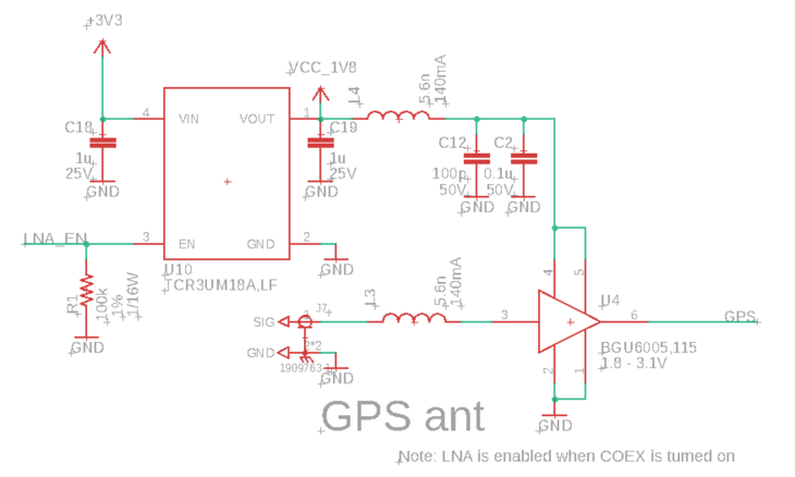
I also did not include the necessary circuitry for GPS. Proto2 will have al the necessary circuitry to make GPS happen. Here’s a schematic snippit:
![]()
It’s using an 1.8V LDO + LNA combination. The LNA is a BGU6065 which is specifically tuned for amplifying GPS signals.
- I also did not include the necessary circuitry for GPS. Proto2 will have al the necessary circuitry to make GPS happen. Here’s a schematic snippit: It’s using an 1.8V LDO + LNA combination. The LNA is a BGU6065 which is specifically tuned for amplifying GPS signals.
With those features added, the top side of the board is packed to the gills. I still could likely add some other components but not after some serious finagling!
![]()
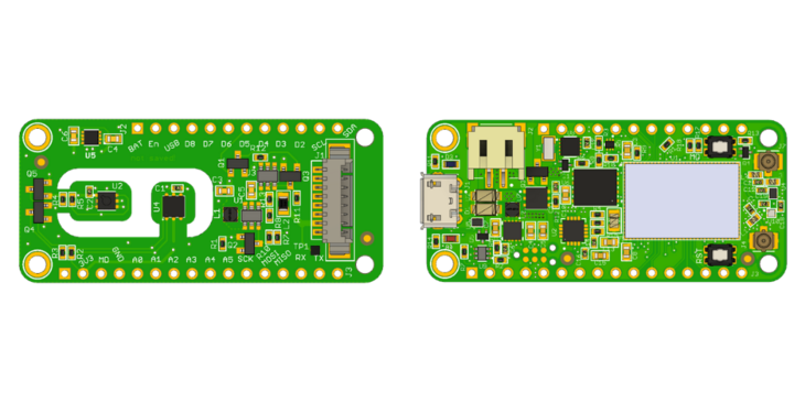
The nRF9160 Feather
A fully featured LTE Cat-M1 and GPS enabled Feather. It sports everything you'd expect from a Feather and more.
 Jared
Jared