There were a few overall design goals in this design:
- Light weight
- Designed as single axis tracker
- Uses external USB battery pack that backpacker may already have
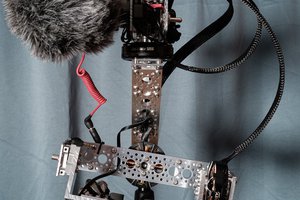
- Capable of carrying mirrorless camera with telephoto lens
- Must be strong enough, stable enough
- Low cost, easy to reproduce
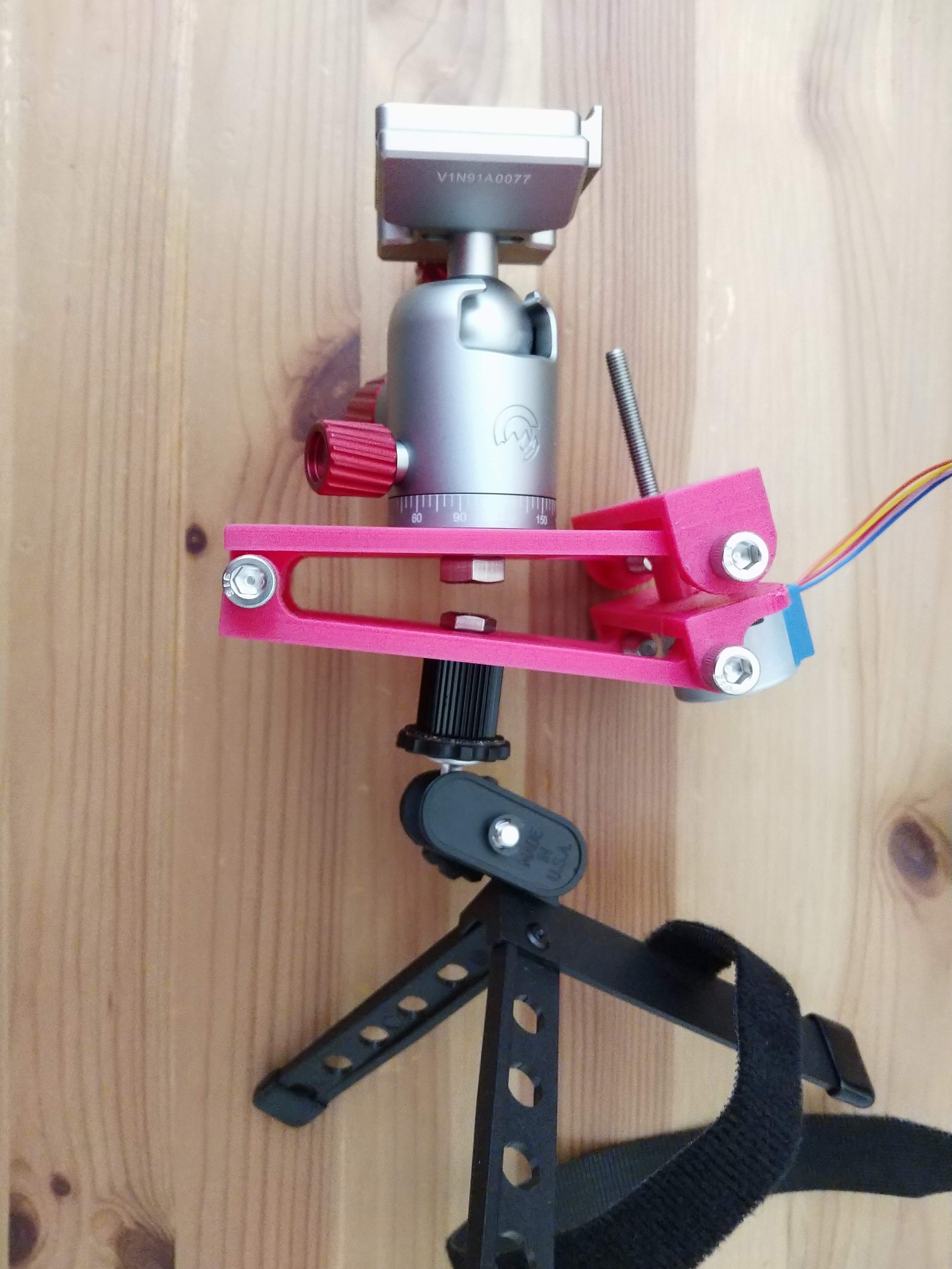
- Easily printed 3D printed frame
- Simple design, small enough for most printers
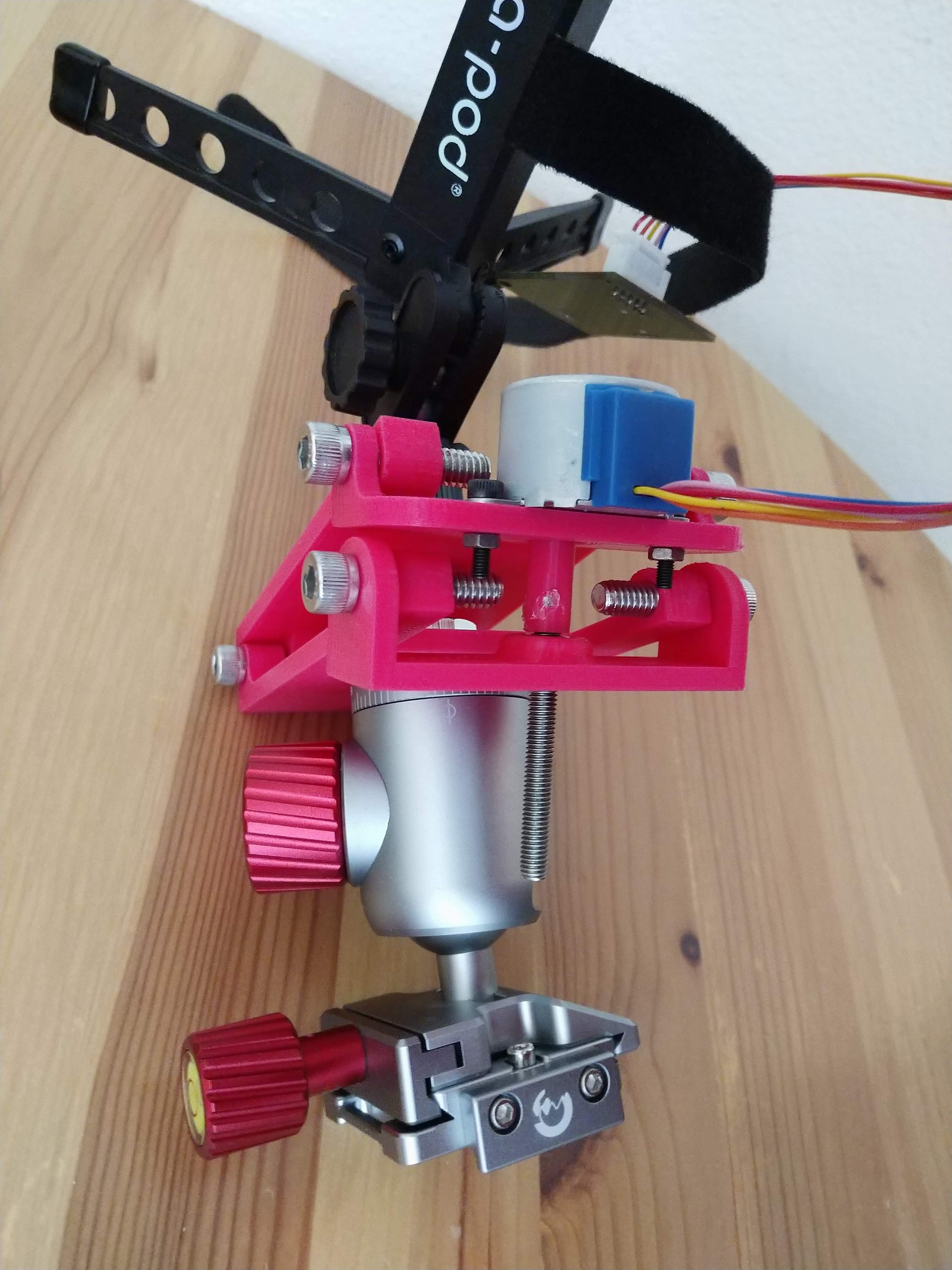
- Simple bolt hinges
- Threaded rod actuation
- Common, cheap 28BYJ-48 stepper motor
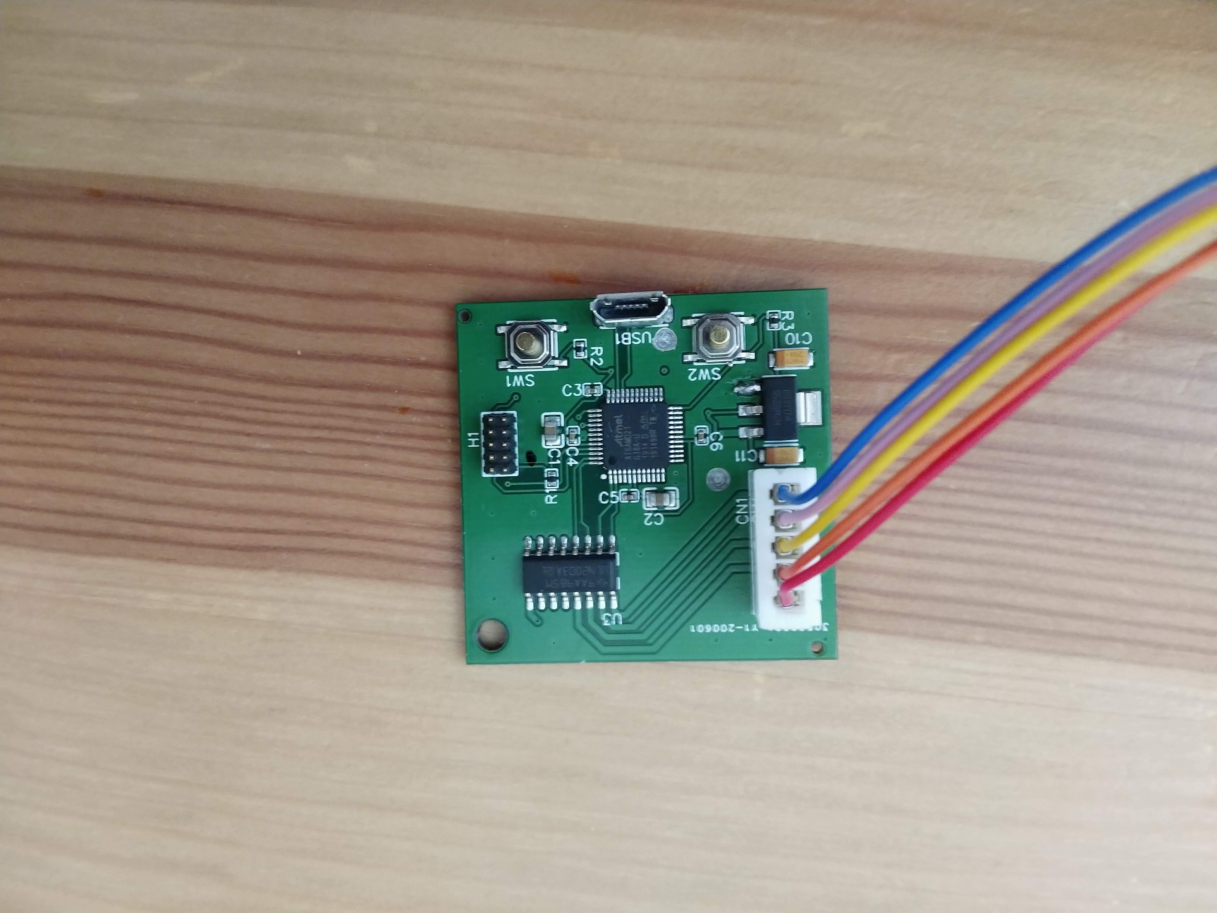
- Single custom PCB from JLCPCB
LOGS
 Matt Barr
 ahorn42
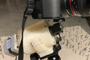
 Chris
Chris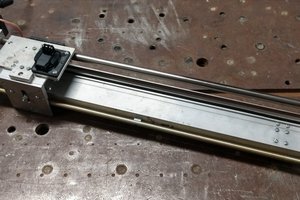
 willbaden
Hi,
Project looks great and I'd love to build one, do you have the project files posted somewhere?
Viz. Step files, pcb files, hardware and software?
Thanks - B