Close
0%
0%

2020 HDP Dream Team: CalEarth

The 2020 HDP Dream Teams are participating in a two month engineering sprint to address their nonprofit partner. Follow their journey here.

Similar projects worth following
The Challenge-

Automated Options for
SuperAdobe Building Processes:
One potential drawback to the SuperAdobe system is that it’s a very laborious method of construction. The intensity of labor accounts for the vast majority of building expenses.

This challenge asks teams to automate or mechanize parts of the building process in order to maximize efficiency, and drive labor costs down, without compromising the integrity of CalEarth’s vision to ensure accessibility and affordability of the technology.

The Team:

Sameera Chukkapalli
Architect & Director of NeedLab
Spain, Barcelona, Barcelona City.

Jason Knight
Product Designer
Eindhoven, Netherlands, Eindhoven

Alex Whittemore
Electronics Engineer
USA, California, Redondo Beach

Introduction

CalEarth's mission is to further the research, development, and education of Superadobe, a safe and accessible form of Earth Architecture that provides environmentally and financially sustainable living spaces. CalEarth is engaging in ground-breaking research and education that fundamentally transforms housing options worldwide.


Mission

Increase the demand for sustainable construction by creating a global trend for “Superadobe” homes by flag shipping in the US and Europe.

Key Point:

  • Developed countries set the trend for building and lifestyle

Goals:

  • Increase market share and mind share of SuperAdobe
  • Make SuperAdobe “A thing” in developed countries
  • Propagate SuperAdobe outword

Strategy:

  • Make construction less labor-intensive for well-resourced deployment scenarios in developed countries.

HDP 2020 Dream Team Initial Concept Review: CalEarth

Summary of three weeks work here. 

Pain-points (Chosen)

  • Labor intensive 
  • Compass - Profile sail
  • Mechanism to fill the bags
  • Ability to mix soil and control humidity
  • Plastering
  • Burlup bags Vs Plastic bags
  • Move material, Vertically
  • Safety during construction

Key Research Leads

Profiling of the structure

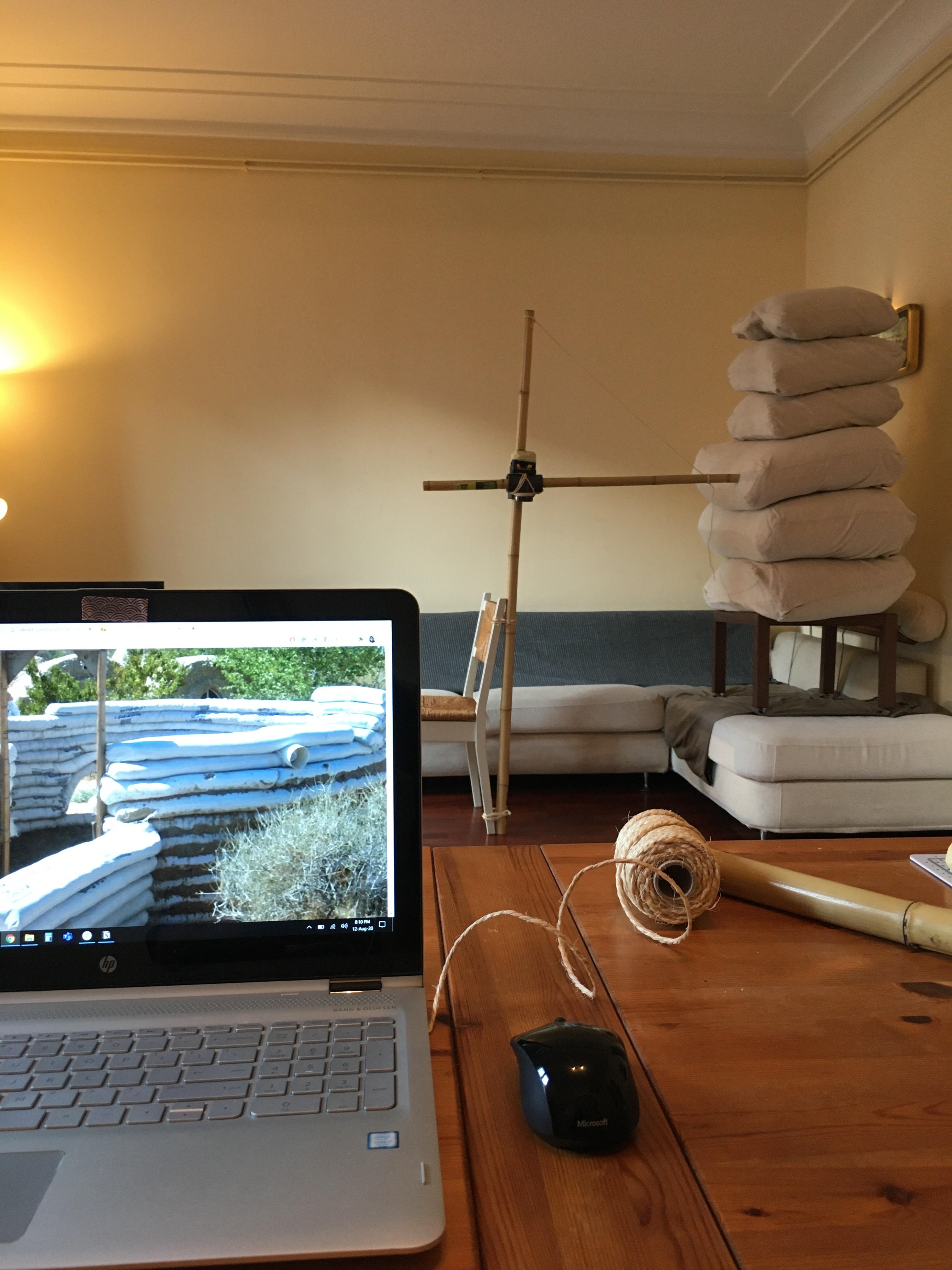
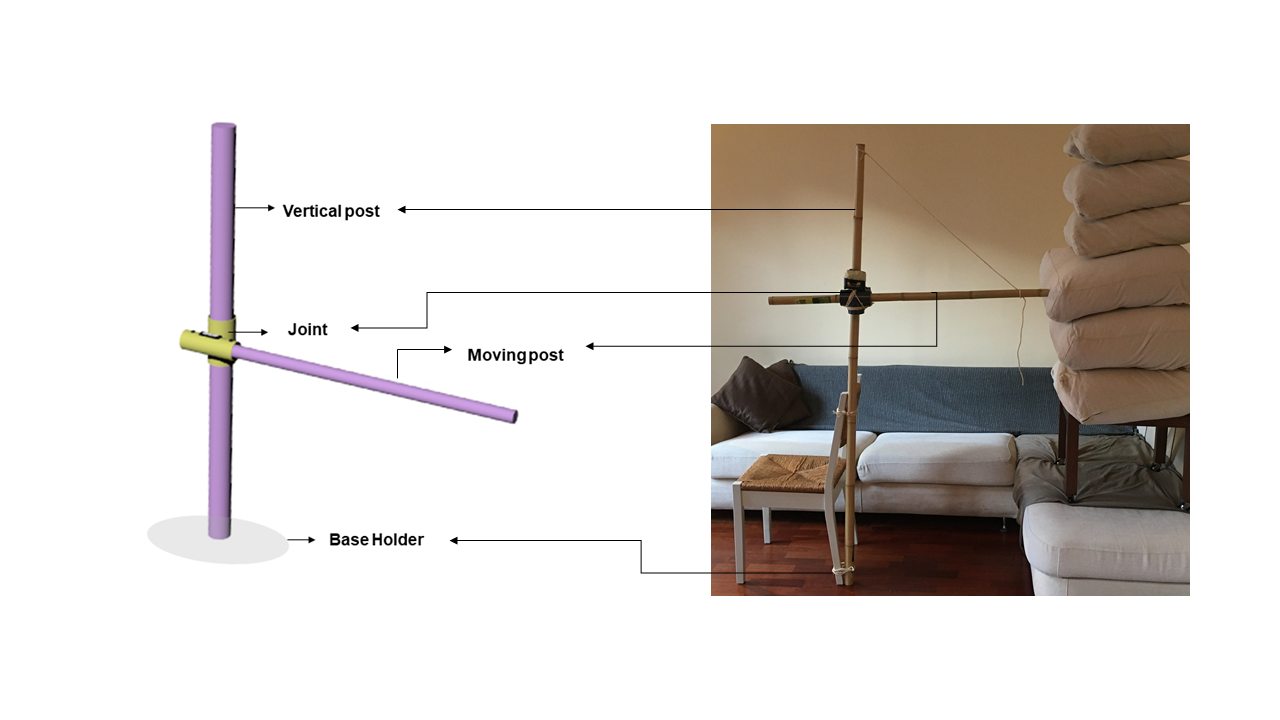
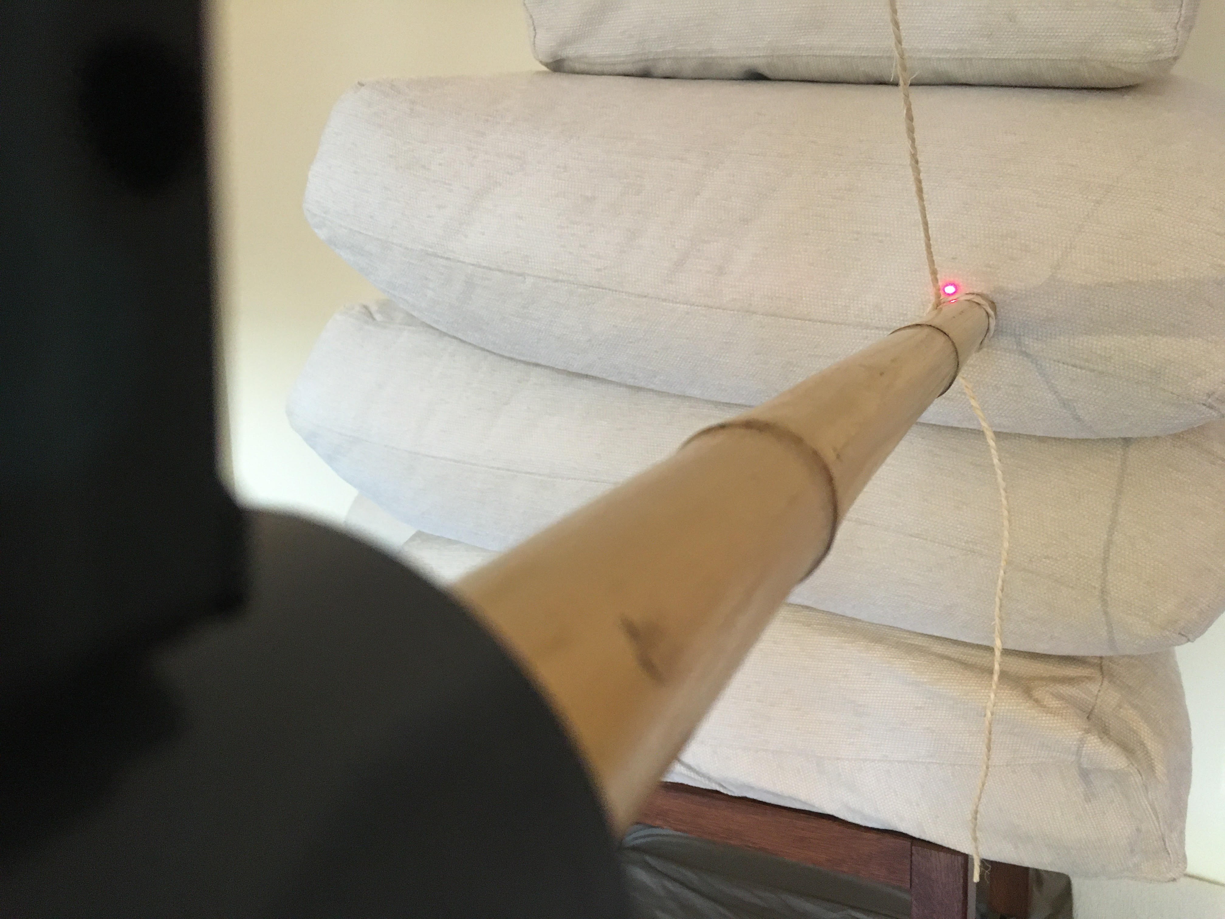
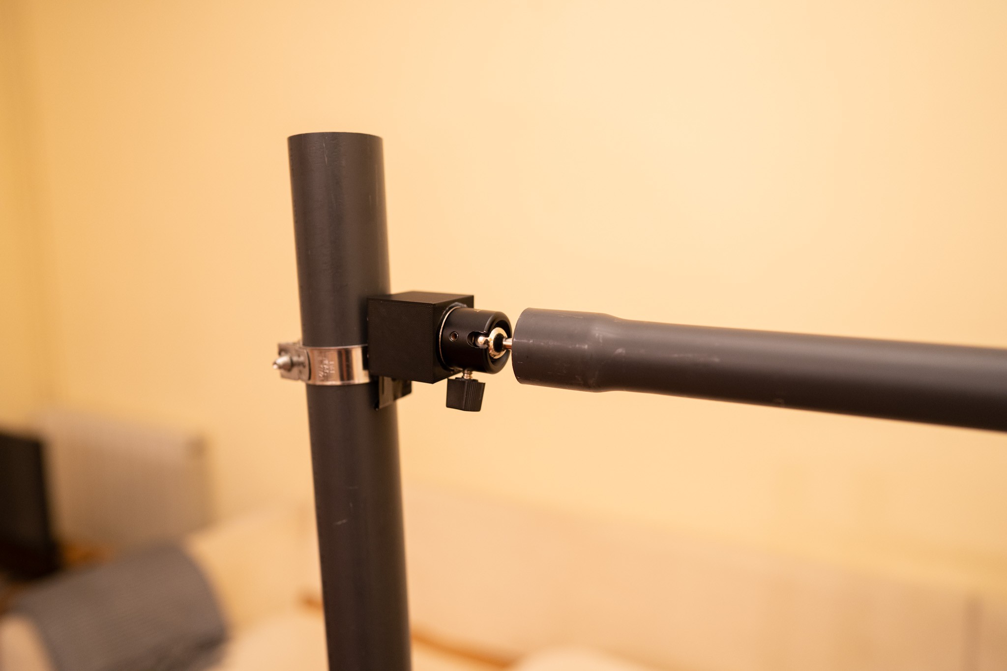
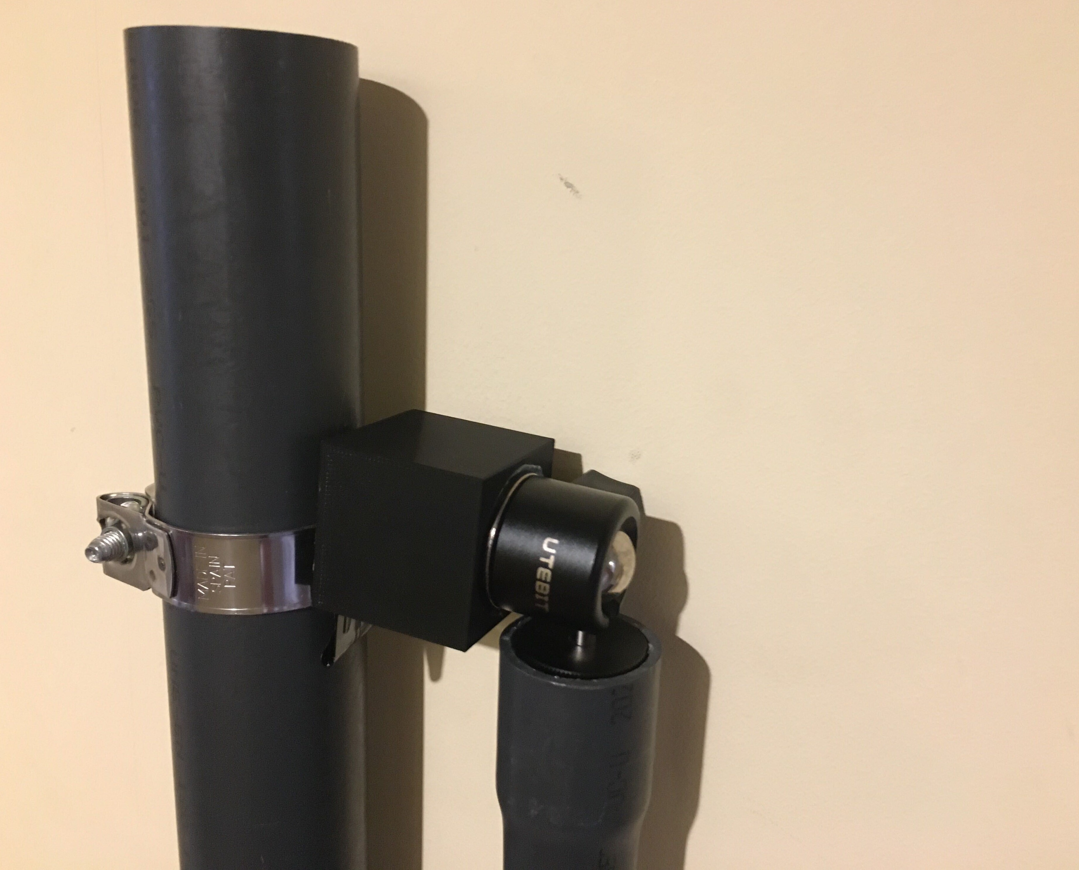
There is dependence on the person doing the “compass profiling task”. The rest of the team members have to wait for this person to indicate where the next layer is placed and how much is the overlap. Finding an alternate way to make the profiling of the domes easy that would save a lot of time and money (as workers are waiting). We’ll be presenting

  • The “LIDAR Compass” concept; a high-tech highly-integrated highly-flexible approach (still relatively cheap at ~$350)
  • The “Pipe Sail” concept; a relatively minor variation on construction and usage of the current sail concept. ($ 35)

Make the build appealing and less labor intensive: Develop compacting and filling tools that are automated. These concepts include

  • A bag funnel to assist in bag management and earth loading to hopefully streamline handling
  • An Earth Extruder which could automate both filling and potentially packing as well, 

Research results and next steps

Final presentation.pdf

Hackaday Prize Dream Team CalEarth Final presentation and next steps.

Adobe Portable Document Format - 2.93 MB - 10/14/2020 at 11:48

Preview
Download

Abstract Presentation.pdf

Hackaday Prize Dream Team CalEarth Initial Concept presentation.

Adobe Portable Document Format - 5.14 MB - 07/21/2020 at 16:52

Preview
Download

Research line two.png

A low-tech prototype solution sketch.

Portable Network Graphics (PNG) - 137.01 kB - 07/14/2020 at 15:14

Preview
Download

Research line one.png

A medium-tech prototype solution sketch.

Portable Network Graphics (PNG) - 186.94 kB - 07/14/2020 at 15:13

Preview
Download

RP_LIDAR.pdf

Manual for the LIDAR we are running experiments on. This is the product currently in testing - You can expect some hacking and some improvements from our end to make this product both user friendly and purpose-oriented for the CalEarth construction site.

Adobe Portable Document Format - 1.64 MB - 07/14/2020 at 15:03

Preview
Download

  • LIDAR Compass: Laser Safety

    alexwhittemore09/03/2020 at 14:49 4 comments

    The LIDAR Compass fires two separate lasers in a bunch of directions, which calls to mind some concerns about eye safety. How do we make sure that, in the course of normal operation, we don't accidentally blind anyone?

    You'd be right to guess that a safe bet here is to just use a low-powered run of the mill red laser diode. Unfortunately, red isn't, in my testing, especially visible after getting flung around and spread into a big circle by the spinning mirror. Green would be a much better option.

    Green laser modules are very cheap and plentiful, but it's VERY hard to get modules that actually do what they claim. The "laser enthusiast market" being the primary consumer of such modules, most that you can find output WAY higher power than they say, and also omit other safety precautions that add up to extreme non-eye-safety. In particular, the ultra-common and high-brightness 532nm green lasers all over the internet are DPSS - diode-pumped solid state. In this topology, an 808nm laser diode fires at one crystal that absorbs the 808 and re-emits 1064nm light, which then hits a second crystal that frequency-doubles that to 532nm. Because each of those two stages is relatively inefficient (something like 20-30% end to end), there's a ton of leftover 808nm and 1064nm laser light coming out the front of such lasers, and when they're built down to a price, they often lack the optical IR-cut filter to remove those frequencies.

    Making matters (much) worse, when those crystals are too cold, they no longer work. So if the device overall is too cold, it'll appear off, while outputting still-blinding invisible IR laser light.
    The solution we've settled on to get around these concerns is to simply pay a little more for a diode that 1) operates at 520nm, with a direct-emission source (no invisible byproducts), and 2) at the power level it claims of <1mW.
    Luckily, this still produces a bright-green dot that should be visible even outdoors on a job site.

  • LIDAR Compass: Rotor Position Measurement and Feedback Laser Update

    alexwhittemore08/19/2020 at 20:36 0 comments

    A very key aspect of the LIDAR compass is a live visual feedback system using a laser to point out all the positions where the structure is in-spec, so builders can make sure they lay bag in the right spot as they go. This visual feedback system requires a couple of key elements:

    1. A (visible) laser to show where placement is correct
    2. A means of turning that laser on and off while rotating it through the cross-section of the dome
    3. Pursuant to (2), a means of measuring the LIDAR scan head position

    (1, 2) are easy - lasers are cheap and low-power, so it should be no trouble to turn one on and off with just a microcontroller pin. Maybe a transistor, if that's not enough current. 

    (3) is where the real fun lies: a reliable sensor to measure the scan head rotor position that we'll be piggybacking on, and code to handle that sensor appropriately. That's what this update is really about.

    Putting the pieces together

    The last LIDAR Compass update showed a proof-of-concept optical sensor that seemed to do a good job measuring a white dot on the edge of the rotor, and pulsing every time it went by. This update builds on that success, using that sensor and a physical assembly to build the entire chain, from figuring out where the scan head is in its rotation to pulsing the laser for set angular duration.

  • Lidar Physical Design Update

    Jason Knight08/18/2020 at 02:26 0 comments

  • LIDAR Compass: Rotor Postion Sensing

    alexwhittemore08/16/2020 at 22:01 0 comments

    A key feature of the LIDAR Compass concept is a visible laser firing out in the same plane as the sensor to indicate where measurements were taken that fall in-spec of the design. A key enabling factor of such a scheme is that the LIDAR already has a rotating scan head that we can easily piggy-back on for aiming the feedback laser. This does require, however, that we KNOW the precise position of the rotor head at all times, so we can know whether to enable or disable the feedback laser. 

    Sensing Rotational Position

    There are a couple ways to do this:

    1. Hall effect sensor
    2. Magnetometer
    3. Optical tachometer

    In the case of the hall effect sensor scheme, a magnet on the edge of the rotor passes by a hall effect sensor, which measures magnetic force. Whenever the magnet passes, the sensor outputs a pulse, which is read by a microcontroller. The period between pulses gives the average rotational speed over the last full rotation. After timing out a few such rotations, the microcontroller can infer the rotor's position at any time by calculating the solution to (angular position/360)=(time since last pulse/average period). Sensored brushless DC motors use a scheme like this, with a hall sensor at every pole to tell the motor controller when to commutate. 

    The magnetometer measurement similarly uses a magnet, but instead of a normal axially-magnetized magnet that pulses a sensor when it goes by, you place a diametrically-magnetized magnet right over the axis of rotation, and put an electronic compass right over that. This is a bit like rotating a bar magnet above a compass: the compass always points in the exact direction the bar magnet is facing at any given time, allowing you to read the rotor position directly. This is a relatively expensive way to do things, and requires having access to place a sensor right along the axis of rotation, so it's relatively uncommon. However, I wouldn't be too surprised if this is how the RPLIDAR A1 itself operates, given the need to know angular displacement precisely.

    The optical tachometer scheme is spiritually exactly the same as the hall sensor scheme, but instead of using a magnet and a magnetic field sensor, you use a reflector and a light sensor. The biggest advantage of this scheme is that you don't have to put a heavy magnet on the precisely-balanced LIDAR rotor; a dot of paint will do. 

    Implementing the Optical Tachometer

    Advantageously, a sensor that looks a LOT like this is pretty common in DIY robots. Since infrared LEDs and photodiodes are both quite cheap, cheap toy robots very often use simple reflectance sensors based on these parts for obstacle detection. An LED lights up the scene, and if the photodiode sees enough reflected infrared light, the sensor triggers, assuming a nearby object is reflecting that light. 

    The sensor pictured above, $9 on Amazon for 5, includes a dual op amp and a trim pot to let you set the sensitivity, and to threshold the measurement into a digital "obstacle/no obstacle" output. That happens to be almost everything we need to make an optical tachometer: the only additional item we need is a "snoot" or shroud to direct the infrared light at our paint dot on the rotor, and make sure the receiver photodiode ONLY sees light reflected from that dot. A simple job for a 3D printer:

    This feels almost too easy at this point, but it's worth pointing out here one gotcha of this idea: plastics are very often transparent or near-transparent to infrared, especially acrylates, even when colored. It's very possible that this snoot doesn't work well enough to block other sources of reflectivity without an additional coat of paint or something. But let's go ahead and try it anyway (printed in black PETG). We'll be looking to measure the white paint dot on the rotor below. Note that it isn't really critical WHERE the dot is placed, as long as it's not the same plane as the measurement laser so our sensor for it won't block the measurement. We'll have to calibrate...

    Read more »

  • Working Prototype 1- Pipe Compass

    Sameera Chukkapalli08/14/2020 at 15:57 0 comments

    A Living room simulation of Cal Earth construction site. 

    In order to test the prototype, pillows were used to represent each layer of super adobe bag. 

    Due to travel restriction and limited access to experiential ground space the testing of the prototype was adapted in Barcelona, Spain. 

    Working Prototype Parts

    The moving post is indicating the correct position of the super adobe bag. 

    The laser measuring the distance for the reference of the site handler. 

    User Manual. 

    Step 1: Preparation of site - Make a firm/ stable base holder. 

    Step 2: Insert the vertical post into the base holder. 

    Step 3: Clamp the Joint to the vertical post.

    Step 4: Insert the moving post into the joint.

    Step 5: Refer to your construction diagram/ Cal Earth app to get the accurate measurement for the next layer of the super adobe bag. Measurement from the center of the Vertical post to the center of the super adobe bag. 

    Step 6: Place the Super adobe bag and start filling it with composite mixture, fill the bag completely. Remember not to complete the ramming of the super adobe bag. 

    Step 7: Click the measure button on the Joint, Check the displayed measurement on the LCD screen. 

    Step 8: Adjust the super adobe bag as you are ramming it in place in order to match the display measure with desired measurement from the construction drawings. 

    Step 9: Use the moving post to touch the center of the rammed super adobe bag to cross-check the correct measurement. 

    Step 10: Un-clamp the joint and move it along the vertical post for the next layer of super adobe bag. 

    Continue the same process until you complete all the super adobe layers. 

  • Earth Funnel Proof of Concept

    Jason Knight08/11/2020 at 21:19 0 comments

    The video shows the first test of the earth funnel to fill a 3m Superadobe bag. It feels easy to use, is light and allows the user to move and position the Superadobe bag with one hand and load earth using the other hand. The first 0.5 meters the weight of the bag is not enough to pull the bag off of the funnel so you have to do it by hand but after that it has enough weight to anchor itself so you can just slide the funnel along and it lays the bag for you.

    Next steps for future development based on first test:

    • Add 4 handles
    • Secure the rubber band better to stop it sliding off occasionally
      • Tighten
      •  2-4 Extra band bands to hold this one on place (tangent to the circumference band)  
      • Make tube smaller but keep out ring the same size so the distance between the two diameters is wider.
    • Flat lip on edge of larger funnel to put your feet on to hold flat to the ground when you are loading the tube
    • Instructions to explain how to use
      • Fully load tube before sliding.
    • Make from final material (Sheet of recycled plastic)
    • Make larger funnel smaller to reduce awkwardness
    • Add a groove or a guide so bag lays in the right potion

  • LIDAR Compass Milestone: Verify a rectangular room

    alexwhittemore08/11/2020 at 18:35 0 comments

    Here's the next milestone for the LIDAR compass: verifying that my office is "correct" given the static measurements I made with a laser tape measure of 2.663m floor to ceiling, and 3.901m wall to wall.

    It turns out, the office is NOT "correct" - the ceiling slopes up a little from the outer wall of the house to the center, which is actually captured in the LIDAR feedback by the top-left corner being out of spec. For this test, I actually relaxed the pass/fail criteria to +/- 5cm instead of 2cm. Note: this isn't 5cm orthogonal to the wall, it's radial to the LIDAR. So a 5cm error where the wall is perpendicular to the laser radius is huge, whereas 5cm in the corners might not be much wall displacement from "straight" at all.

    At this point, a significant source of error may be that the program "bins" LIDAR samples into the closest whole-degree, then just assumes the distance measured is EXACTLY that angle. Again - when the sampling laser is normal to the wall, this doesn't make much difference. But in the corners where the laser hits the wall at a steep angle, a slight angular misalignment will result in a more substantially erroneous radius.

    I theorize that this angular-rounding is why there are almost no "out of spec" points in the middle of each wall, but some points are "bad" in the corners even when further-displaced points are "correct" again. The binning scheme is effectively introducing noise to the radius measurements.

    For now, I have no intention to rework the code and correct this issue, as it involves substantial complexity and isn't yet critical. Eventually, I'd like to move to a system of, instead of storing 360 samples, one for each "degree" and each with some discrete angular error, storing a list of "all samples from the last 5 sweeps" including all of the actual angles at which they were taken. This sacrifices the convenience of being able to pick out angles from their position in the list, but should add almost arbitrary angular resolution, which we may eventually need to get better feedback laser performance.

    Note: The code corresponding to this milestone is in the Git repo as lidar_mpl_blit.py, at tag rectanguar-room-milestone https://github.com/alexwhittemore/CalEarth-LIDAR-Compass/blob/rectangular-room-milestone/lidar_mpl_blit.py

  • LIDAR Compass: Live Feedback

    alexwhittemore08/10/2020 at 22:33 0 comments

    Last week, I showed the LIDAR system "verifying" a straight wall by printing out 1s and 0s to a terminal, to denote whether the distance measurement at that angle was "correct" to within +/- 2cm for a straight wall orthogonal to the 0* line from the LIDAR.

    This is that same test, but running with a live visualization I put together using Python and Matplotlib. Blue-colored points are the "correct" distance assuming the infinite wall, while red points are "incorrect." You can see that as I rotate the LIDAR, the wall drifts in and out of "correctness." as more or fewer points fall within the +/- 2cm tolerance. 

    It turns out, it's PRETTY hard to repeatedly update a Matplotlib plot in a performant way that doesn't take a ton of processing time away from your main run loop. Most of the effort to achieve this was fixing performance issues with mpl.

    It may not seem like much (it doesn't to me), but this represents SIGNIFICANT effort towards the end-goal of live pass/fail feedback via laser.

    I'll try to post code publicly ASAP.

  • LIDAR Compass Milestone 1

    alexwhittemore08/07/2020 at 22:04 1 comment

    Milestone 1 isn't fundamentally complex, but here's some proof that it works! Most of the effort spent on this milestone actually went into discovery and experimentation with things beyond the milestone goal, like figuring out data formats and available information, how the LIDAR device works in practice, and so on.

    Have a look at it working to profile a straight wall below:

  • LIDAR Compass Project Plan

    alexwhittemore08/07/2020 at 18:36 1 comment

    One of the most important strategies for actually getting complex work accomplished is to break the complex goals down into more tractable, bite-size problems that can be checked off a list in-order, and that build up to the complex finishing point. It can be easy to see designs from an overly-simplified 10,000-foot view and think, "oh yeah, for sure I can accomplish that by then!" And you may well even be right about that - I think that's true for this LIDAR design concept. The very beauty of it is that most of the complexity is available off-the-shelf, and the end-use can be boiled down in features to a fundamentally very basic proof of concept. 

    But thinking like that still obscures the actual effort that's required to accomplish the end goal, and adds the mental overhead of having to figure out which piece to bite off next. Thus, without further ado, and arguably later than we should have gotten around to it, I present you with a list of LIDAR Compass milestones and scheduled completion dates:

    Vertical wall verifier POC.

    8/7/2020 (That's today!)

    A simple iteration of the device that measures the distance to a vertical wall at 0° then verifies via on-screen feedback that the next few measured points are, indeed, on that same wall (plus shows their error). This is a very simple test case that, more than anything, proves I still know how to do basic trigonometry. If the POC works, it will basically light up a table of values in Python with "OK!" when the device is oriented perpendicular to a nearby wall, and those values will fall out of "OK" if the device angle changes at all. This will also start giving us a good idea of how much distance error there is in the LIDAR points, given that the walls of my house can be verified straight.

    This milestone is due today, and isn't actually done YET, but work is going smoothly and at this point I'm spending more time on nice-to-haves and future work than on just knocking out the milestone itself.

    Normal room verifier POC

    8/10/2020

    Same as above, but instead of only assuming one infinite wall, takes a model of an actual square room and verifies all points in 360* based on that. Assume a fixed distance from the ground, and fixed observation angle relative to the room. This isn't a huge step on top of the first milestone, which is why it's so close in time. But it is a big step in usefulness of the system, and sets us up nicely for the next milestone.

    Laser feedback POC

    8/14/2020

    Builds on the above POCs to include visible-laser projection of go/no go onto wall. This is probably the biggest individual step of the project, and it might be ambitious to get it accomplished in only one calendar week. In theory, it's as simple as anything else, but in practice, it's the one piece of system integration where there's no prior-art, and it's where all the unknowns lie. For instance, the laser pulsing system may need to be independent from the Raspberry Pi running the show for reasons of time-stability, since the Pi processing and GPIO is hardly real-time. It may be possible to get the rotation synchronization signal for the LIDAR rotor directly from the LIDAR itself, but again, real-time constraints may not be sufficient in practice, and we're not even sure if the T0 of rotation is even available in software. This may require adding an external hall sensor to measure and time rotor movement, which isn't fundamentally complicated but IS a significant addition to the project scope. And so on.

    Self-contained POC

    8/21/2020

    All of the above, running independently on a raspberry pi with some kind of remote login. In fact, we'll probably already get to this point by necessity as of the previous milestone. But one thing we haven't talked about yet is ingesting arbitrary geometry to profile in the form of a 2D DXF, and this milestone will contain that deliverable as well. This may well be a zero-effort step in terms of hardware, but once again DXF processing is, in my opinion, where the real software unknowns...

    Read more »

View all 31 project logs

  • 1
    Low Tech Pipe compass

    This is a tutorial to make a low tech pipe compass that will enable easy measurement for placement of next superadobe bags during the construction on CalEarth Dome structures.

    Final product: Low tech pipe compass. 

    Pros

    • It can rotate and maneuver over different construction elements easily. 
    • It helps builders measure the exact location for the placement for the next bag. 
    • It can fold flat vertically when not in use to accommodate uninterrupted movement on the build site.
    • It is stable and easy to attach and detach and move to different layers. 
    • It is affordable and robust. (can withstand dusty build sites)

    The compass can be flattened vertically as shown in the image - It becomes a vertical member in the center of the build site and does not create any obstructions for the build process. The metal attachment enables builders to move the horizontal measuring pipe very easily without the need of any tools. 

    Step 1: These two parts designed using Rhino where 3D printed. These will be the Part A and Part B of the Pipe compass. 

    Step 2: A polyvinyl chloride PVC pipe is used as the measuring pipe and the 3D printed Part A is inserted into it. 


    Step 3: The Part be is attached with a metal clip which can enable attached of the Part to the metal clamp. 

    Step 4: Part A and Part B are attached to each other with a ball & socket joint which will enable the movement of the Pipes.

    Step 5: All the parts are attached to each other and the measuring pipe can rotate and move on top of the Superadobe bag to enable measuring the placement of the next bag. 

    Please watch this entire video to have complete understanding of how to install the vertical pipe to the ground. 

    Next steps: 

    • Pipe compass needs to be integrated with the digital measuring device. (Currently they are not) 
    • Needs a product designer to convert the 3D printed files into moulds for casting Part A and Part B in HDP Polymer. Then the parts will be more durable and ready for testing on ground. 
    • A test from start to end of production and assembly needs to be tested to make the product - Market ready. 
    • A rough estimate of 5000$ is needed for this product to be made market ready.

    This pipe compass will be sent to a build site for testing and user feedback will be gathered to make improvements. 

View all instructions

Enjoy this project?

Share

Discussions

Similar Projects

Does this project spark your interest?

Become a member to follow this project and never miss any updates