0%
0%
vector-06c mini
A 50% size replica of my favourite 8-bit computer
 svofski
Become a Hackaday.io member
Already have an account? Log in.
Just one more thing
To make the experience fit your profile, pick a username and tell us what interests you.
Pick an awesome username
hackaday.io/
Your profile's URL: hackaday.io/username. Max 25 alphanumeric characters.
Pick a few interests
Projects that share your interests
People that share your interests
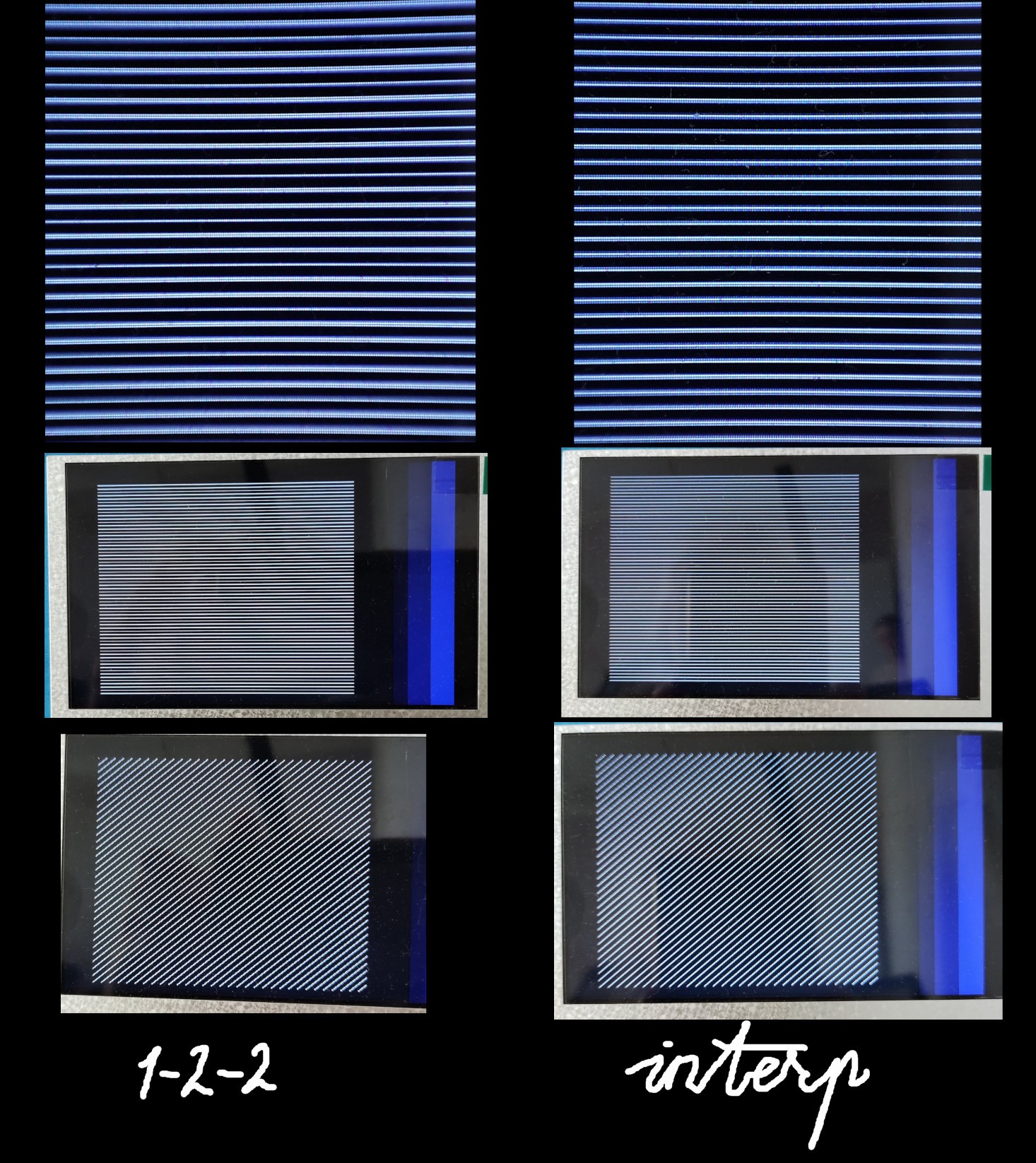
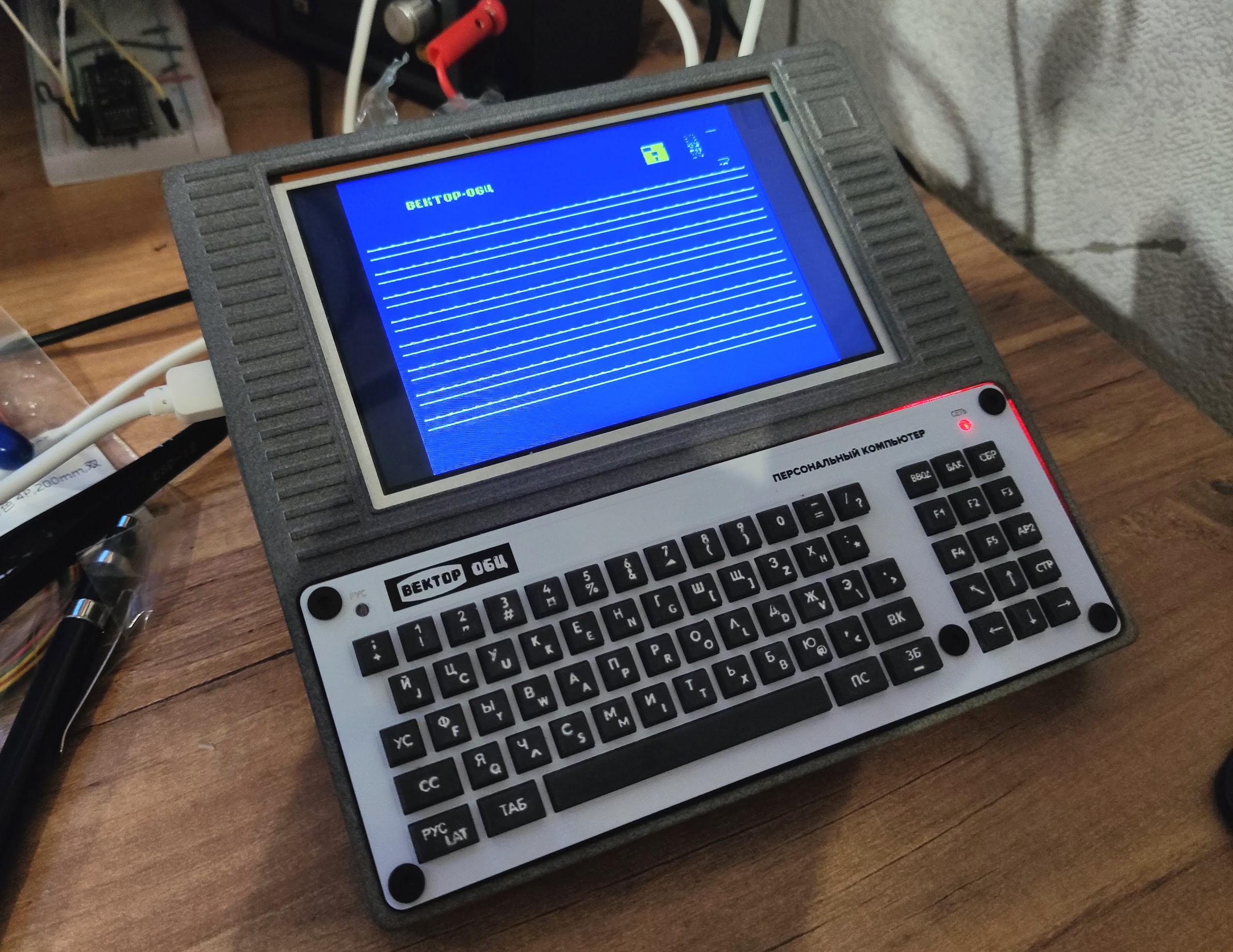
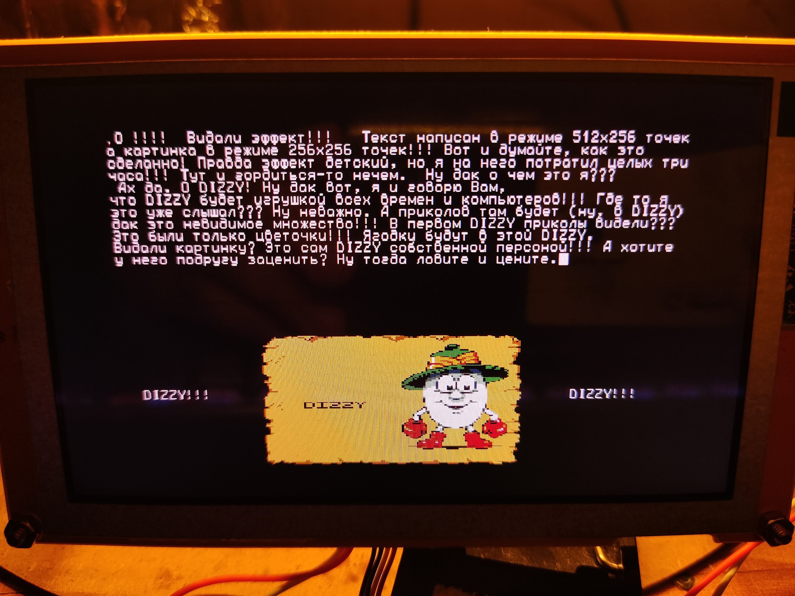
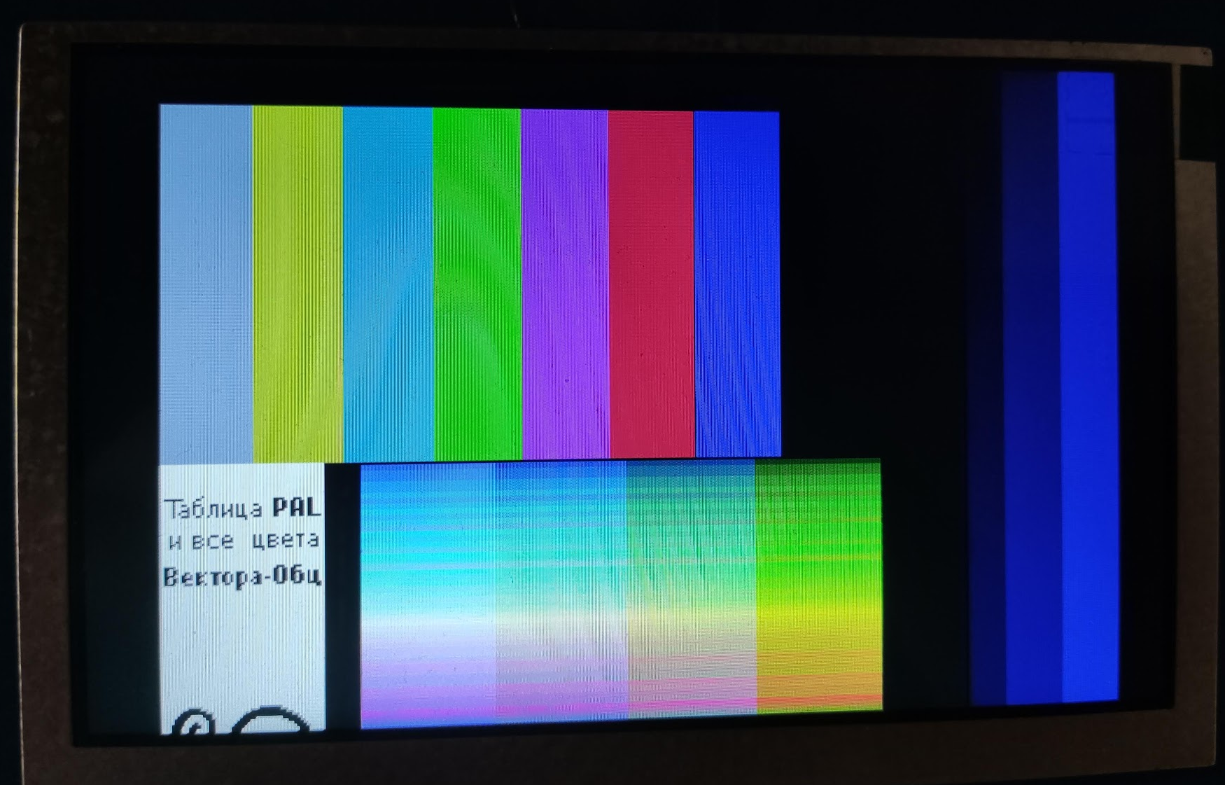 There should be no large gap between the white text block on the left and the rainbow bars. But it's still a huuuuuge progress and I'm happy.
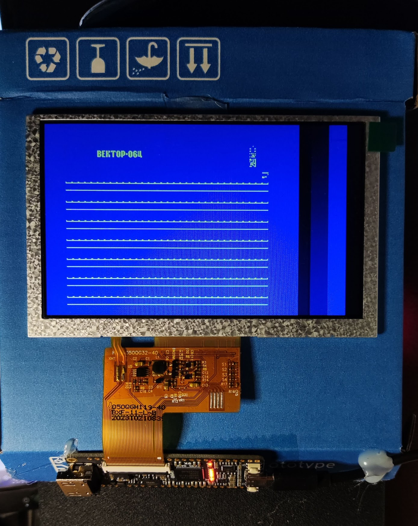
 Yeah.. maybe another try.
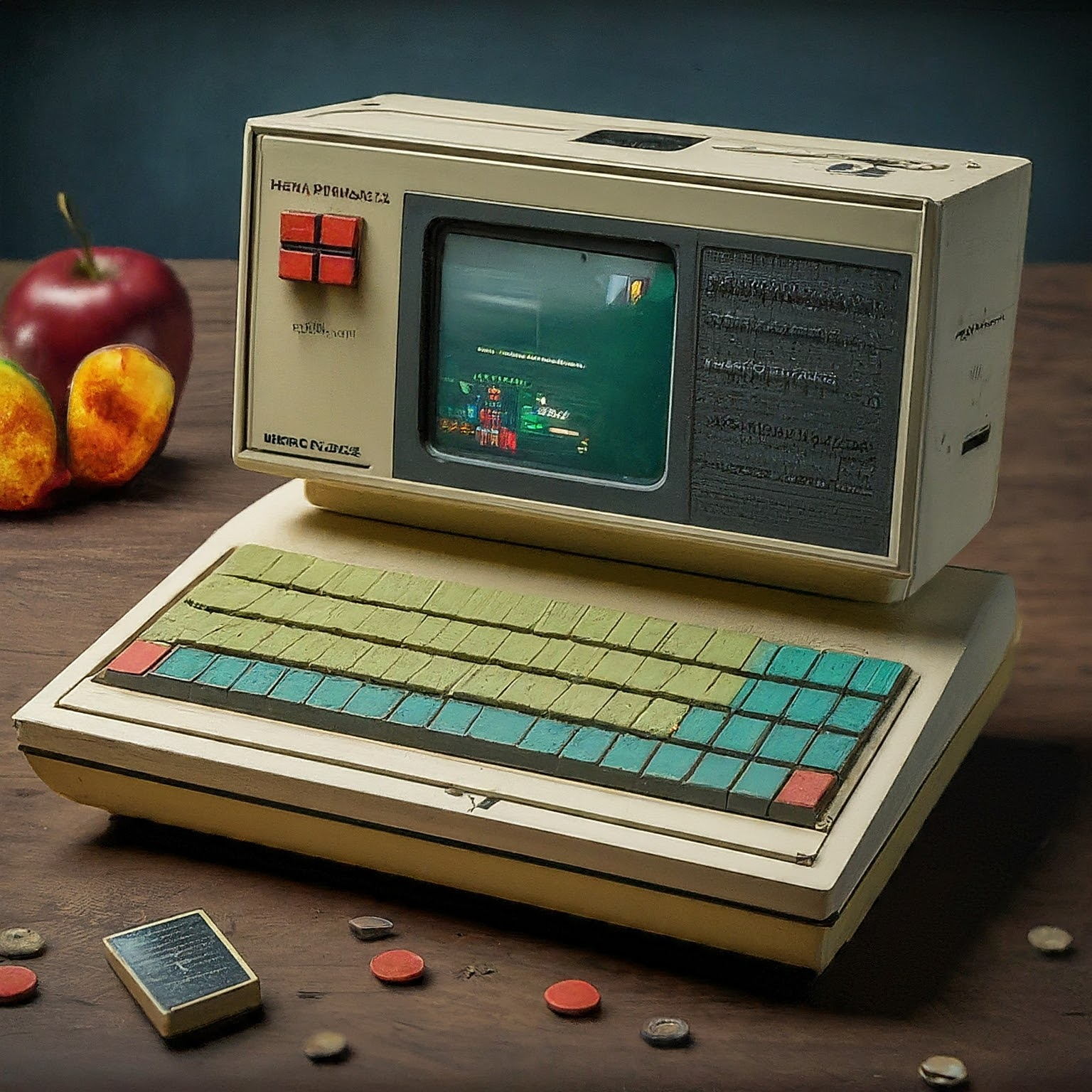 Nevermind, AI.
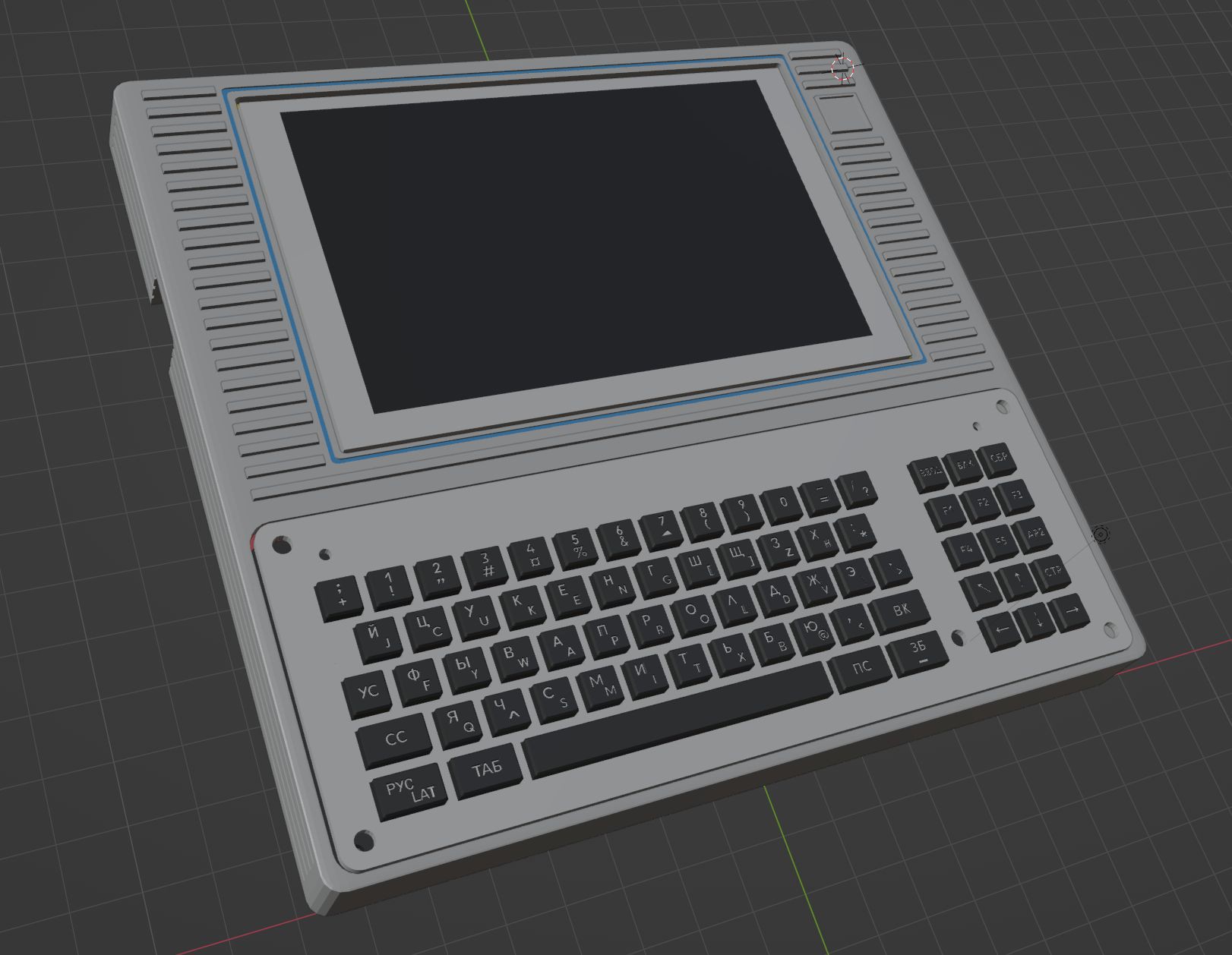
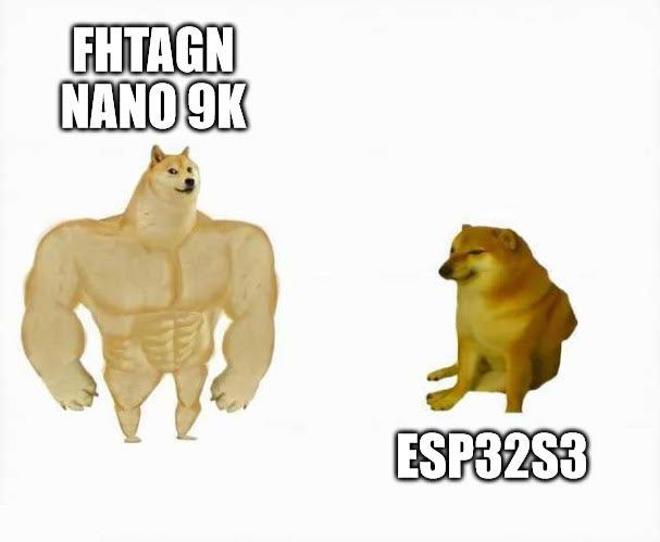
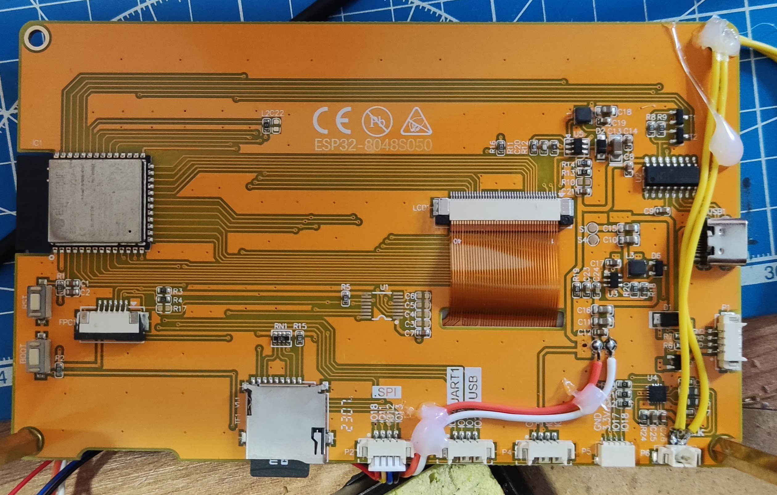
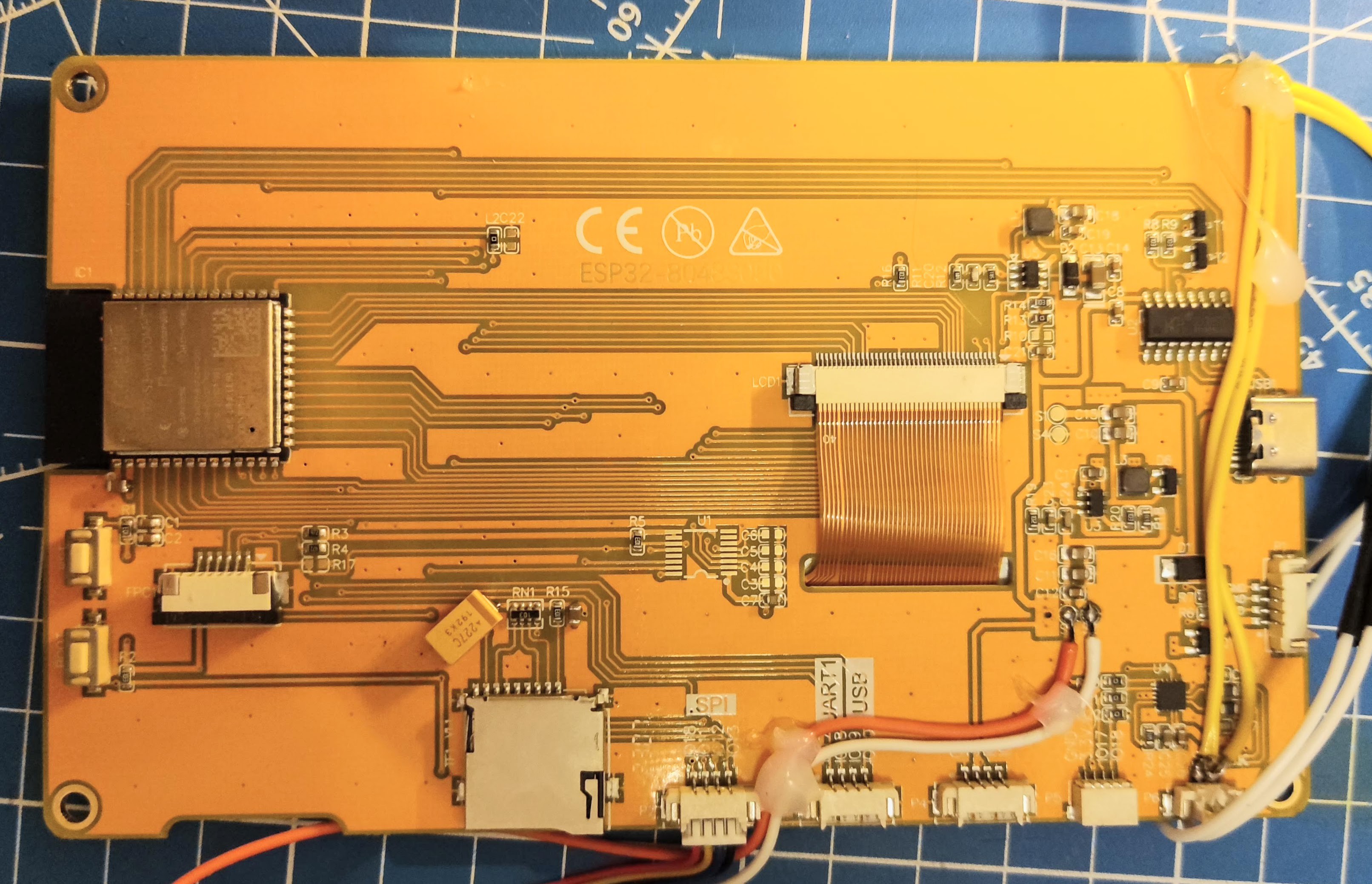
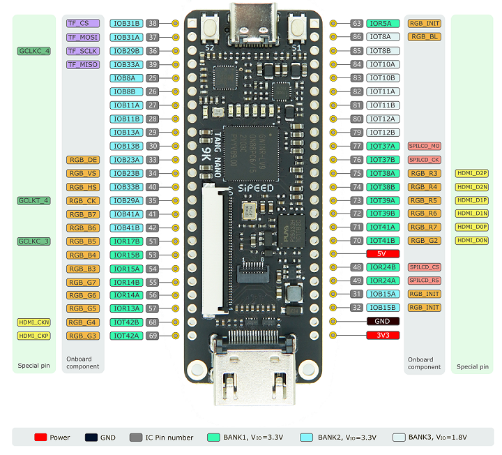 At least on the surface, it seems a fairly decent chip, also packaged on a fairly neat board. Maybe it could become the core of v06x-tiny/fpga, who knows!
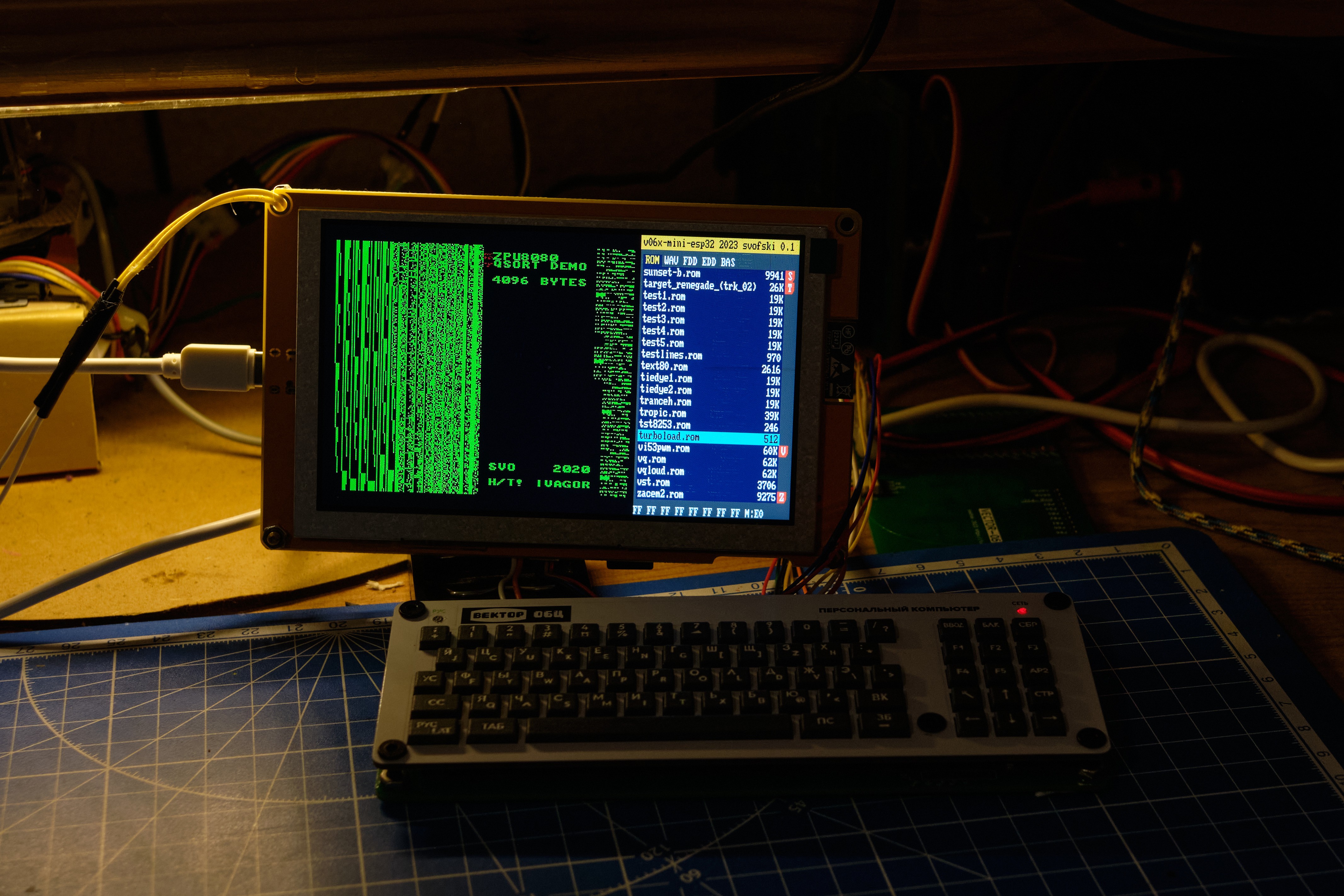

 thpoll
 Stephen Holdaway
 T. B. Trzepacz
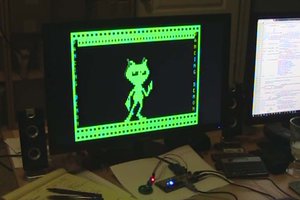
 ziggurat29