 Arduino Enigma
Here are a set of PCB that are accurately wired like the rotors and reflectors of an Enigma Machine.
This project was inspired by: https://hackaday.io/project/156935-enigma-machine
Rotor dimensions from: http://enigma.hs-weingarten.de/drawings.php
The gerbers are available at:
https://oshpark.com/profiles/ArduinoEnigma/
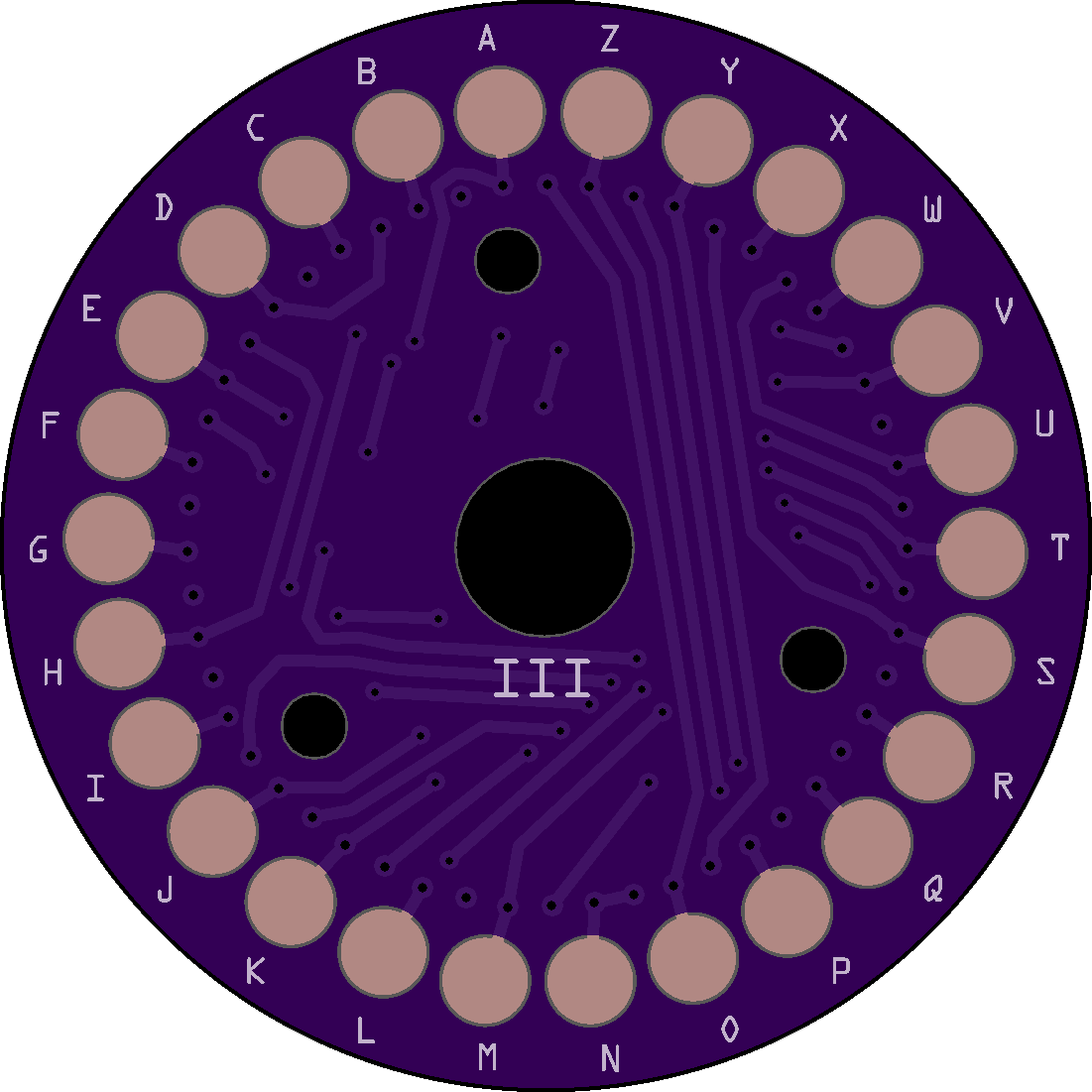
Rotor Wiring:
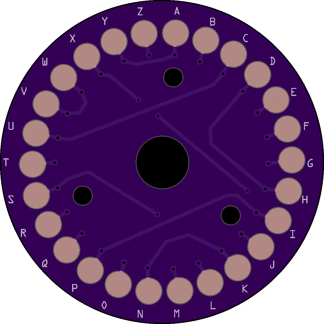
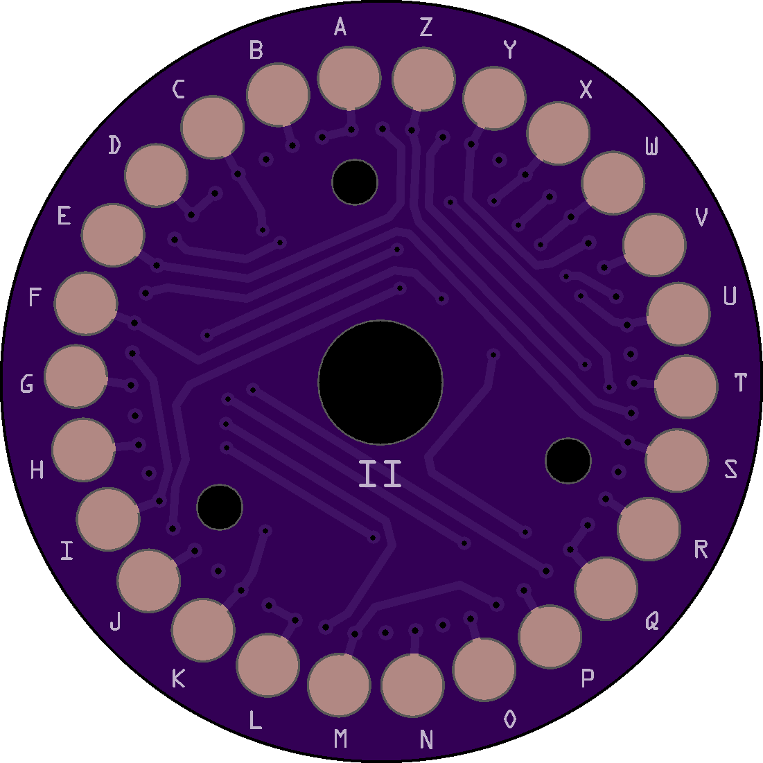
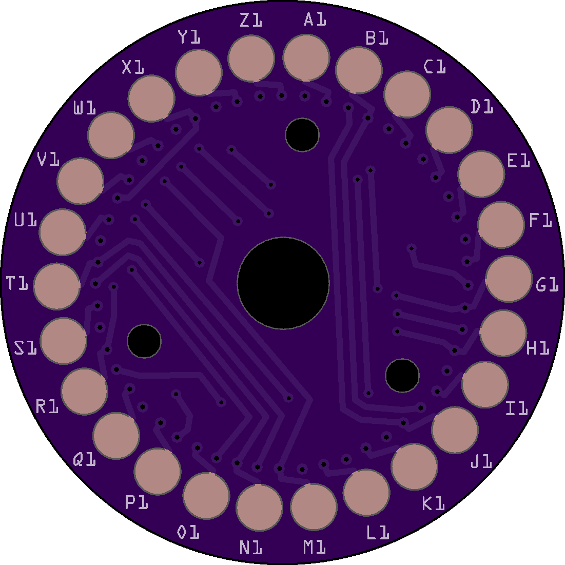
First line: RIGHT SIDE - Bottom Layer
Second line: LEFT SIDE - Top Layer
ETW ABCDEFGHIJKLMNOPQRSTUVWXYZ
ABCDEFGHIJKLMNOPQRSTUVWXYZ
I ABCDEFGHIJKLMNOPQRSTUVWXYZ
EKMFLGDQVZNTOWYHXUSPAIBRCJ
II ABCDEFGHIJKLMNOPQRSTUVWXYZ
AJDKSIRUXBLHWTMCQGZNPYFVOE
III ABCDEFGHIJKLMNOPQRSTUVWXYZ
BDFHJLCPRTXVZNYEIWGAKMUSQO
IV ABCDEFGHIJKLMNOPQRSTUVWXYZ
ESOVPZJAYQUIRHXLNFTGKDCMWB
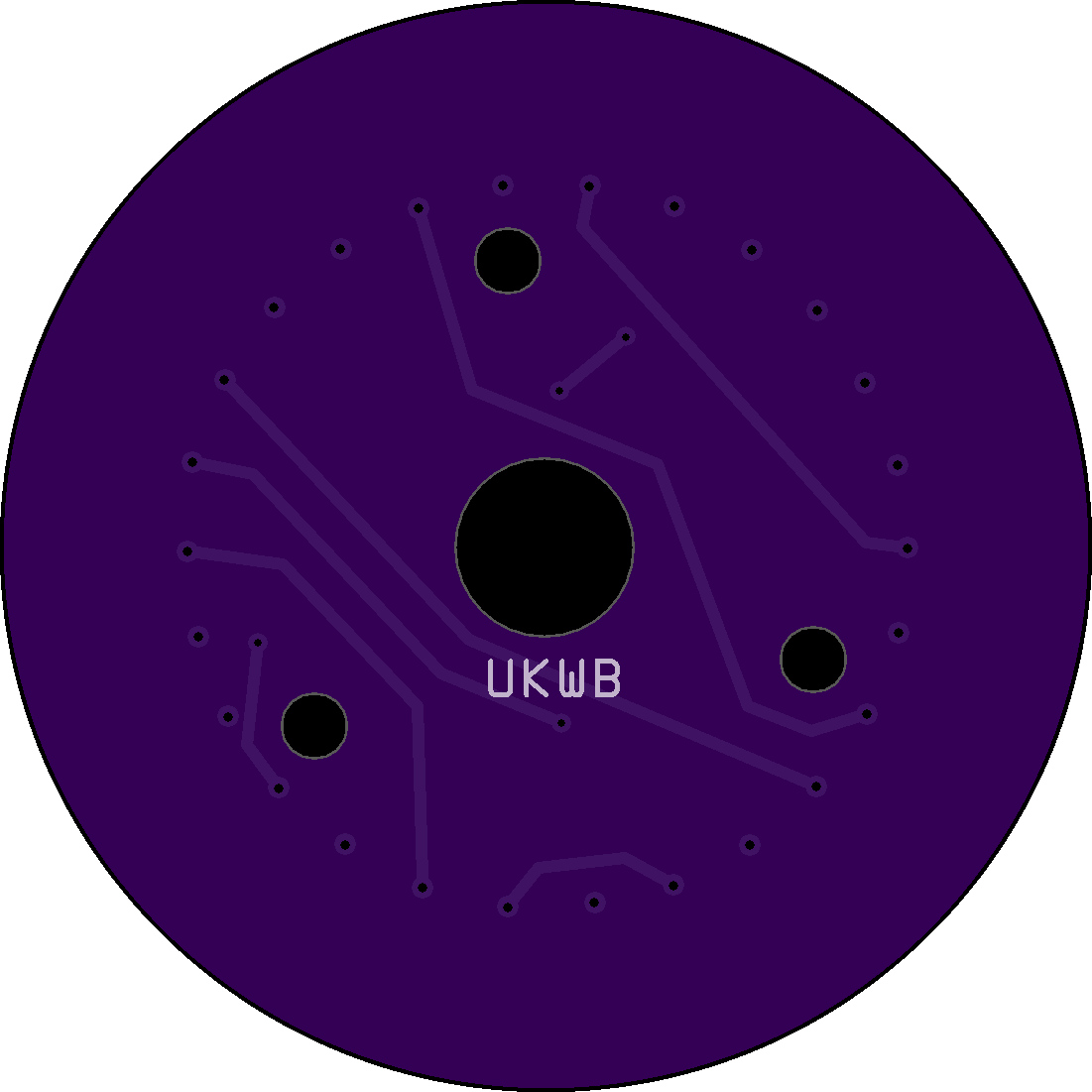
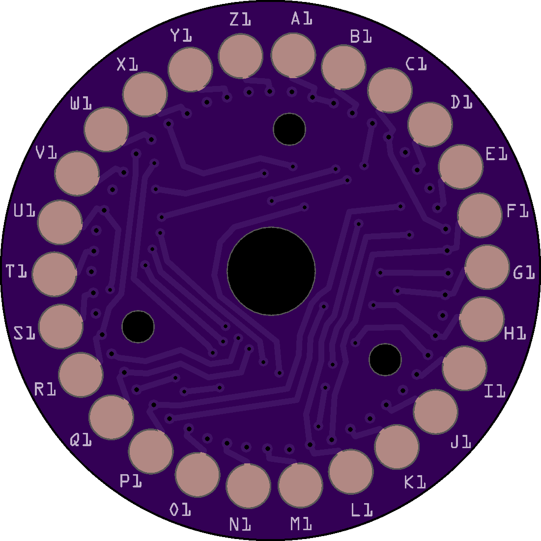
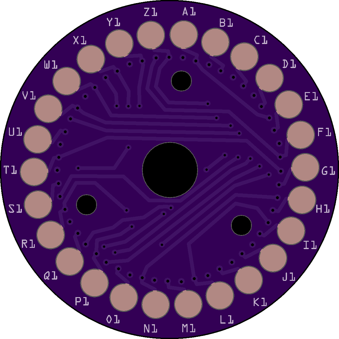
UKWB ABCDEFGHIJKLMNOPQRSTUVWXYZ
YRUHQSLDPXNGOKMIEBFZCWVJAT
UKWC ABCDEFGHIJKLMNOPQRSTUVWXYZ
FVPJIAOYEDRZXWGCTKUQSBNMHL
To use:
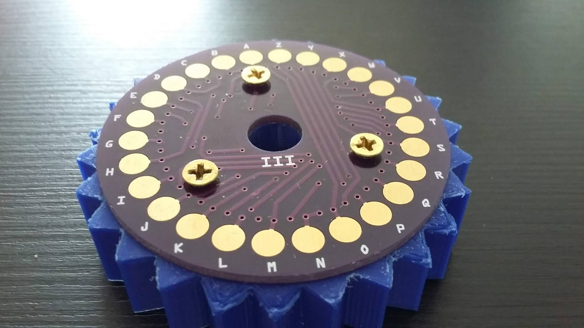
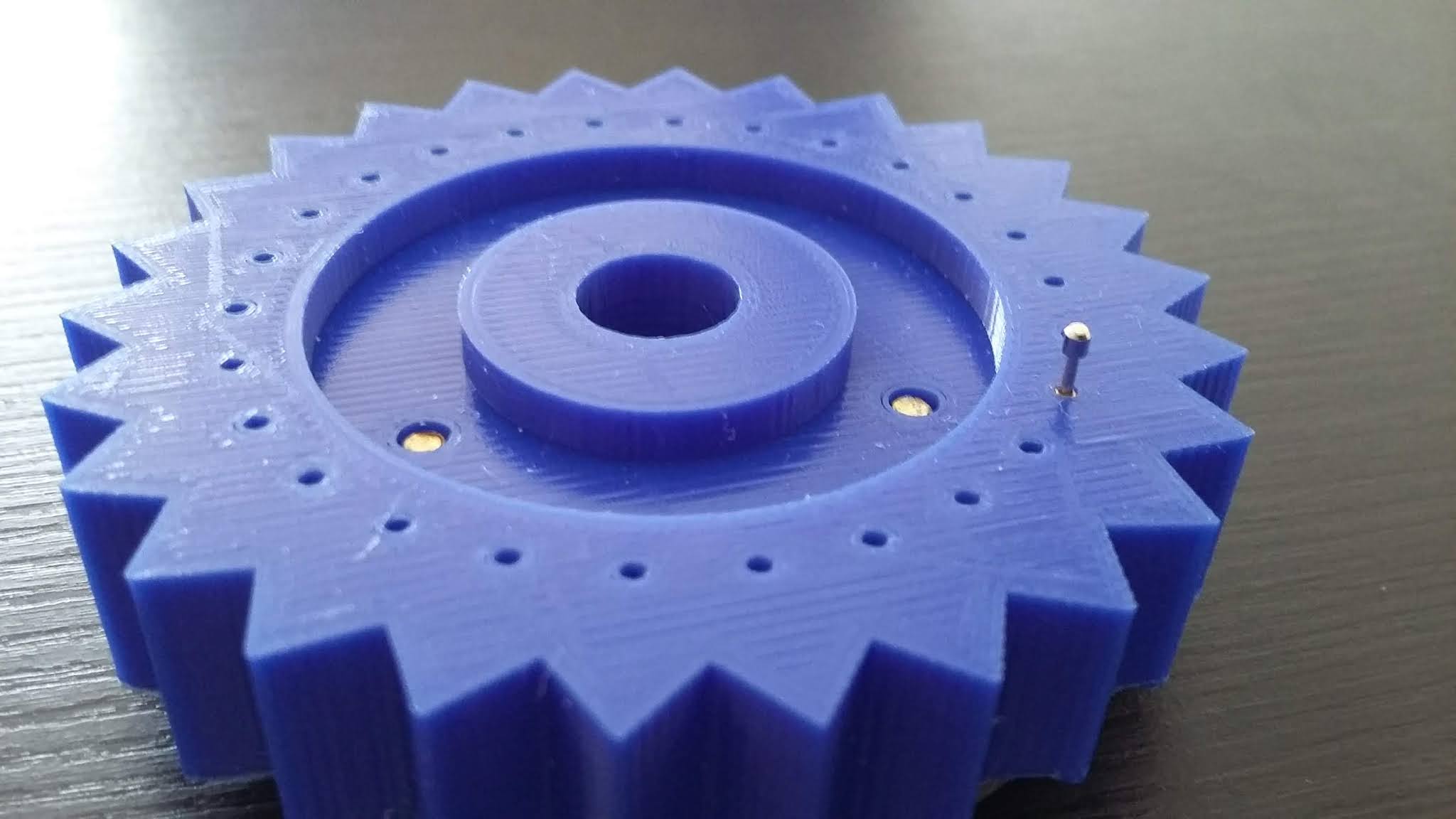
The rotor PCB are bolted to a 3D printed part. The order, from left to right is:
PCB, 3D printed Part, Head of Pogo pin.
The PCB markings are meant to be exposed and on the left side of the PCB when bolted to a 3D printed part.
The ETW takes no pogo pins. The wires from the keyboard are soldered to either the exposed vias or the A1..Z1 contacts on the right side.
The UKW will have its dark side on on the left. The contacts will be on the right and hidden when bolted to a 3D printed part.
To make a machine, the minimum set of parts, from left to right are:
UKW(B or C), Rotor 3, Rotor 2, Rotor 1, ETW.
The wires from the keyboard switches go to the ETW (stationary entry wheel), the signals then go through the three rotors, in and out of the UWK (stationary reflector), back through another parh through the three rotors, then out of the ETW to the lampfield.
For a diagram, see https://www.cryptomuseum.com/crypto/enigma/working.htm


 Lithium ION
 elmerhandojo
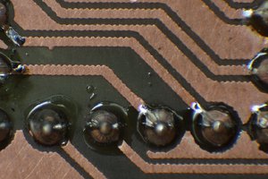
 fruchti
I am currently building a 3-rotor Enigma. My goal is to have it mechanically 100% correct according to its original specifications/blueprints. On the electronic side I am substituting some of the older technology for new--my goal is 75% correct. Your Enigma PCBs are at the top of that "new" list as their wiring correctly mirrors the German wiring specifications for all of the rotors.
The problem is the attachment holes are in the wrong place for all of the rotors and the ETW (Entry Disk). The only disk that aligns properly are the UKWs (Reflectors). Because the Enigma operator sets up the machine via 3 windows (so they can see the letters or numbers on the rotors) in the closed case, the viewing angle requires that the first contact (top position) on all disks is NOT "A" but "B"; consequently, "B" is always at the top so you can see "A" in the window. The position of the holes in your PCBs puts "A" at the top. Here is a link that goes into more detail.
https://www.cryptomuseum.com/crypto/enigma/wiring.htm
As I see it the solution is to move the three holes (by one position) on the ETWs and all Rotors and to re-program you circuits around them so that "B" is at the top. The PCBs are a brilliant idea and of great value to Enigma builders. Do your own homework on this to see if I missed anything.