-
1Overview and Info Gathering
It's recommended to watch the video to get a general feel for design principles and some of what's involved in the assembly, and it would be good to carefully read through instructions before attempting!
-
2Fabricate and Procure
At this point, it's time to procure components for the build and to start fabricating. Bill of materials is listed in Components Section of this page along with some links to parts I used.
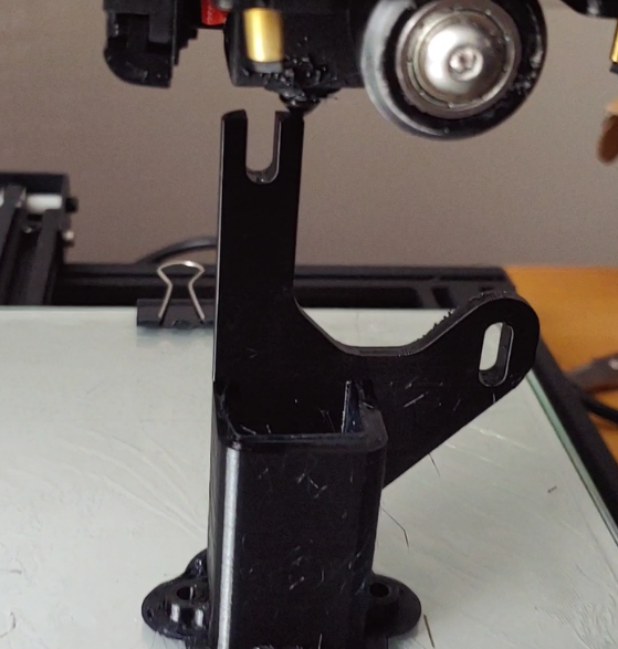
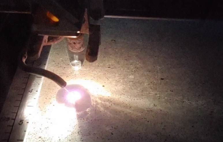
For the 3d-printed parts, I've used an FDM 3d printer (Creality CR-10): .stl files included, and for the base plate + connector piece, I used a laser cutter: .dxf files included.
In order for full thread engagement + not having screws poke through the bottom, I recomment 1/4" or thicker Acrylic for the laser cut pieces.
For those using a print bed that's less than 300mm x 300mm --> I recommend printing the "shorter" of the two racks. Another option (if you want the longer one) would be to design and cut a laser-cuttable rack, maybe with some sort of a 3d-printed adapter for mating to the 8mm rod.
-
3Install Heated Inserts
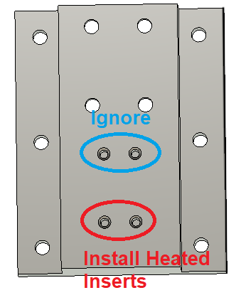
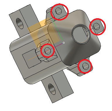
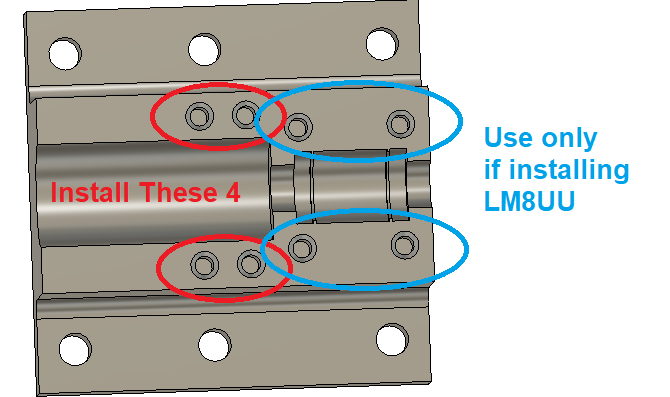
Note: some of these heated insert spots were never actually used in the final version, so I've tried to indicate where they aren't needed
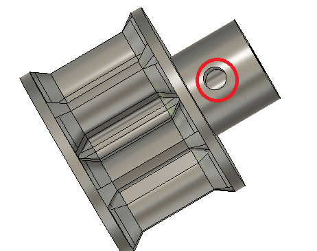
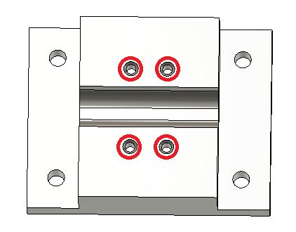
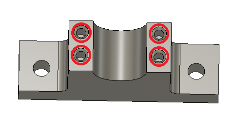
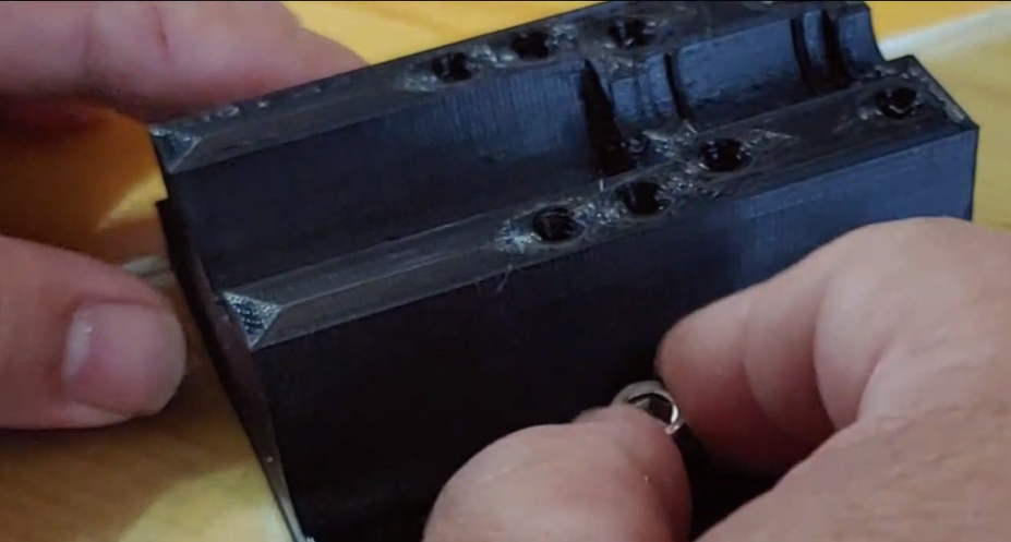
Using a soldering iron (either with a "normal sized' tip or with a heated insert-specific tip), install the heated inserts. If it's your first time doing this, I recommend printing a few test pieces and trying this process out before doing it on a part you care about!
Components w/ Heated Inserts
- Motor Mount/Base Plate Bracket
Whistle Top/Fipple:
Pinion Gear:
Stability Bracket:
Pipe and Bearing Clamp Bracket:
Pipe Bottom Clamp Bracket:
-
4Tap Base Plate Pieces
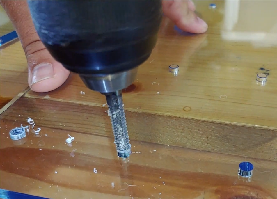
Now that we've got some beautiful, laser-cut acrylic plates, let's take a drill to them! to tap these 1/4-20 holes, I like to use a hand-drill: I get good enough threads and tend not to need cutting fluid on acrylic.
-
5Attach Brackets to Build Plate
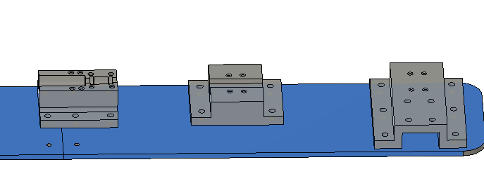
At this point, it's time to use the 1/4-20 x 5/8" screws to attach the 3d printed brackets to the build plate.
-
6Build Up Plunger/Rod/Rack Assembly
(Note: if using LM8UU, make sure to put that onto the rod before this step).
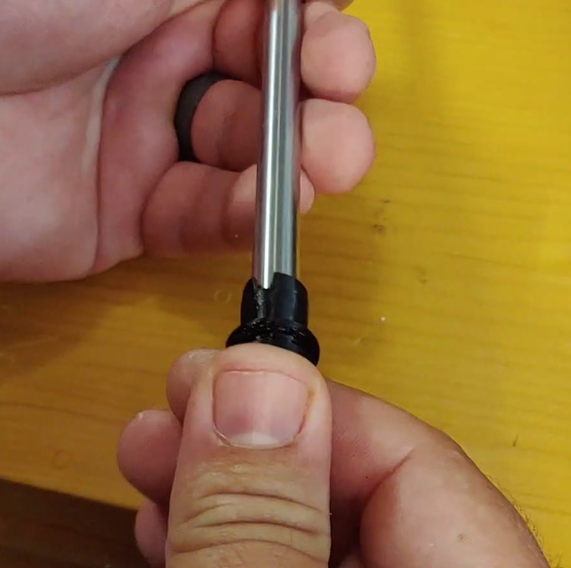
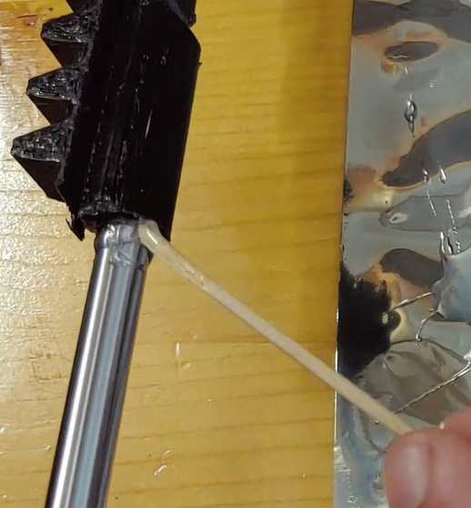
On one end, attach plunger adapter to rod. Now do the same on the other end with the 3d printed rack piece.
Secure in place with epoxy.
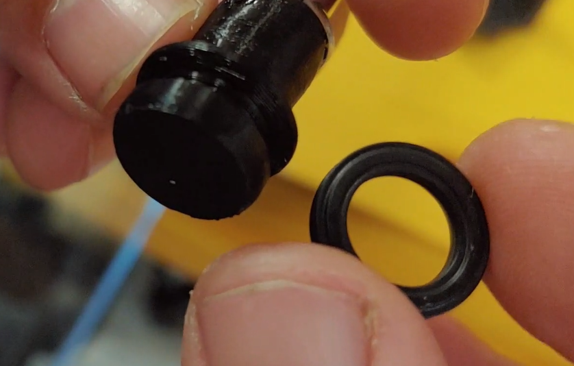
Once the epoxy has dried, attach O Ring to plunger piece (should fit in the little "groove" designed for it)
-
7Insert Plunger and Clamp the PVC Pipe
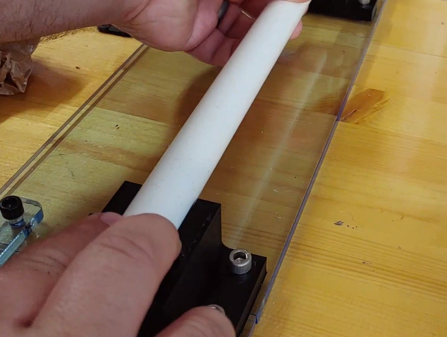
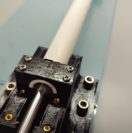
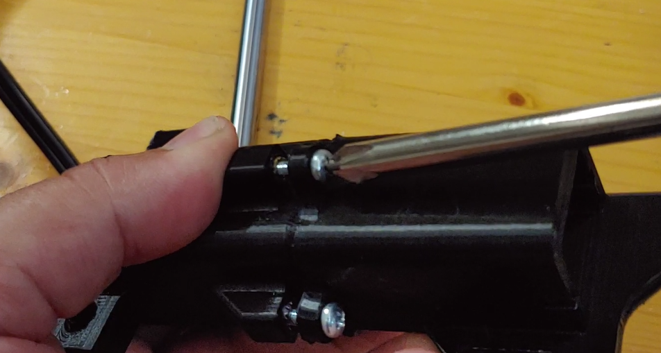
At this point, insert the plunger into the PVC Pipe, place the pipe on the clamp brackets, and attach M3x16 screws through the top bracket pieces to clamp down on the pipe.
-
8Create and Attach Blower Fan Assembly
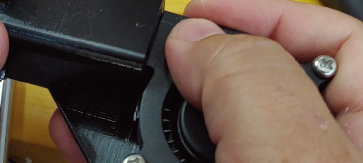
Attach Blower Adapter to Whistle Top components using M3x16 screws:
Then attach Blower Fan using M3x22mm screws and M3 Hex Nuts. Attach loosely, and then slide the fan into place:
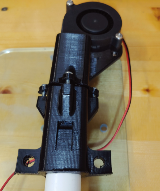
Press Assembly onto the end of the PVC Pipe:
-
9Attach Motor Mount, Motor, and Pinion Gear
Now it's time to get the drive mechanism together. This requires a motor mount, the motor, and the pinion gear to mate with the rack.
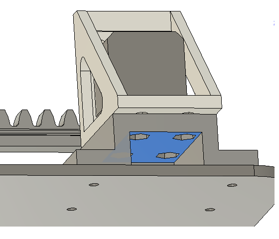
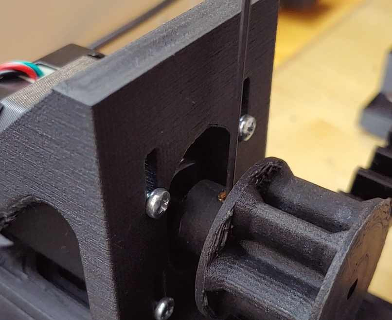
I ended up biasing the motor mount slots to be all the way "back" away from the rack piece before attaching. Unfortunately, the motor makes it difficult to adjust this after-the-fact (needs a re-design), so you pretty much have to pick a position in the slot and stick with it. As mentioned, I would start with it "all the way back". There are 2x M3 screws that hold it together in the front, and 4x 1/4-20 x 1" screws in the back (with hex nuts underneath).
Once the motor mount is attached, attach the motor to it using M3x10 screws. Keep them loose until you've attached the pinion gear and aligned it into the slot.
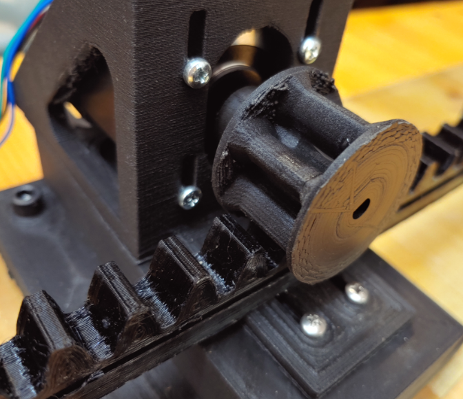
Attach the pinion gear using a set screw. You can leave it a little loose while you're adjusting all the slots here, but once done, make sure it's tight and can spin the motor freely without slipping.
It's a little tricky to fit this on the rack, but with some rotating the pinion and moving the rack, you should be able to get the two to mate. Make sure the motor slots are loose when you do this so you can "lift" the motor/pinion as needed.
Then, bias the motor slots down until you're making good contact between the rack and pinion. That height can be adjusted later if things are binding or are too loose, but "mostly down" is where I ended up.
-
10Attach Electronics, Configure Microstepping
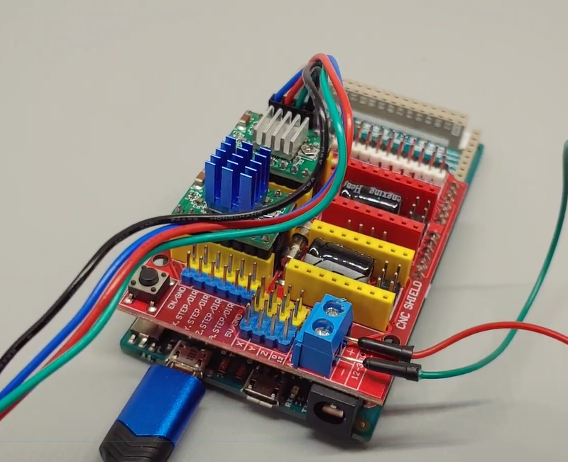
I use the CNC Shield because it makes it really easy to add additional stepper motors and drivers to a project (or let me control more instruments at one time).
Important: For the Arduino Sketch here, it works on the "Y" axis of the CNC Shield and with 1/8 microstepping. So populate the first two jumper positions (M0 and M1) on the shield. And attach the motor. In the StepperOnline motor I used, see image below for polarity. If you get it wrong, you can always flip the connector over (or else change the tuning positions to be negative in code!).
See here for more info about this component: http://www.zyltech.com/arduino-cnc-shield-instructions/
Power up the Fan and the Motor Driver with 24V Power Supplies (or 12V if you go with a 12V fan option).
Note: you can (and should) tune the current for the driver depending on what motor you end up using.
MIDI-Controlled Slide Whistle
Uses an Arduino Due and a stepper motor + driver to control a slide whistle made of 3d printed parts and PVC pipe. Laser-cut base plate.
 TheMixedSignal
Discussions
Become a Hackaday.io Member
Create an account to leave a comment. Already have an account? Log In.
You can buy all control accessories from one website
1. Stepping motor (17HT19S4085 as an example):
https://www.motiongoo.com/index.php?route=product/product&product_id=67&search=17HT19S4085
2. Stepper motor drive board A4988:
https://www.motiongoo.com/index.php?route=product/product&path=59_120&product_id=389
3. CNC Shield interface board:
https://www.motiongoo.com/index.php?route=product/product&path=59_123&product_id=464
4. Arduino UNO:
https://www.motiongoo.com/index.php?route=product/product&path=59_113&product_id=290
Are you sure? yes | no